| Netra CP2140 Technical Reference and Installation Manual |
| Netra CP2140 Technical Reference and Installation Manual |
| C H A P T E R 6 |
|
Firmware |
This chapter describes the structure and function of initialization firmware. The Netra CP2140 board platform comprises a modular firmware architecture that enables the user to customize initialization and test firmware, even enabling the installation of a custom operating environment.
The SPARC firmware consists of two components: Common Operations and Reset Environment (CORE) and OpenBoot PROM. The CORE in its expanded form is Common Operations and Reset Environment. CORE handles the early initialization of the board before the SPARC control is transferred to OpenBoot PROM. It also provides a trap-based interface for the OpenBoot PROM and user firmware.
This platform also employs the System Management Controller (SMC). The SMC controls the CompactPCI interface, System Management and hot-swap control, and some board hardware. The SMC configuration is controlled by separate firmware.
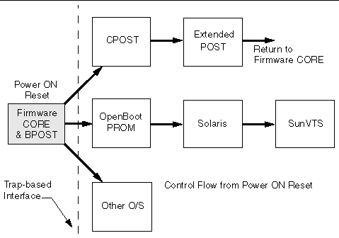
The control flow at board startup is shown in FIGURE 6-1. Execution begins in Firmware CORE, which includes Basic POST (BPOST). Then it passes to Comprehensive POST (CPOST) and Extended POST (EPOST), if these are present, before returning to Firmware CORE and on to OpenBoot PROM.
See Section 6.10, Firmware Diagnostics for detailed information.
BPOST is integrated into Firmware CORE. Its tests are interleaved with the initialization activities of Firmware CORE to present a foundation of validated and initialized hardware to run subsequent code such as that in CPOST or OpenBoot PROM. The tests listed in TABLE 6-1 are examples of CORE and BPOST flow of execution.
|
Note - Not all of the hardware listed in this table is present on this platform. If a hardware item is not detected by the firmware, the firmware makes no attempt to test or initialize it. |
Because BPOST runs from PROM, the extent of testing is limited to that needed by modules that are loaded later. Such a module, for example CPOST, can perform comprehensive testing more quickly because it executes from DRAM.
|
Initialize EBus and bridges in path between CPU and EBus devices |
|
|
Perform basic diagnostics on caches and MMUs[1] |
|
|
Perform partial memory test[2] |
|
|
Set up I/D MMUs with valid mappings; enable MMUs and I/D caches |
|
|
Copy Firmware CORE into memory and transfer control to the RAM copy |
|
|
Execute POST dropin| |
|
|
Locate the client in PROM. If found, copy into memory and transfer control to it |
|
CPOST contains tests for higher level board functions. By placing these tests in a separate module, the user has the option of performing them and the developer can substitute them with other tests. Examples of CPOST tests are:
EPOST is used for additional POST code dropins that are provided by the user.
|
Note - Always upgrade board OpenBoot PROM before upgrading SMC (System Management Controller) firmware. |
OpenBoot PROM exists in the form of a dropin in the System Flash memory area. OpenBoot PROM probes for devices and builds the device tree, a table that contains entries for how drivers communicate with connected hardware. Each line, or entry, of the device tree is a reference for the node entry for the peripheral in the /dev directory in the / directory. The device tree is inherited by Solaris software as it is booted.
To display the device tree, type show-devs at the ok prompt. An example of a device tree follows.
OpenBoot PROM also contains aliases for some of the devices shown in the device tree. These aliases can simplify hardware access at the ok prompt, for example:
The devalias command lists the device tree aliases. An example of the devalias command follows.
This section provides some information on the CORE NVRAM variables and the NVRAM configuration variables.
At startup, Firmware CORE defines a set of variables in the NVRAM for controlling initialization and selecting the amount of testing required. These variables determine the following functions:
Use the key combinations listed in TABLE 6-2 to control the flow of execution at system boot. These key combinations must be pressed at power-on.
The configuration variables are used by the OpenBoot PROM code and are stored in NVRAM. TABLE 6-3 shows a sample output when the printenv command is typed at the ok prompt. Use the setenv command to modify the environment variables. The boot process is controlled by several variables.
The diag-switch and diag-level variables listed in TABLE 6-3 affect the path through the various embedded tests. TABLE 6-4 shows the effect of setting these variables.
BPOST is embedded within Firmware CORE and is executed when the OpenBoot PROM environment variable, diag-switch is set to true and diag- level set to min. Similarly CPOST (and EPOST if it is present) is executed when diag-level is set to max. The permutations are shown in TABLE 6-4.
|
diag-switch[3] set: |
diag-level* set: |
||
|---|---|---|---|
The host board boots from the 1 Mbyte system flash PROM device, which contains the firmware CORE, Basic POST code, Comprehensive POST, and OpenBoot PROM. The contents map of this PROM is shown in FIGURE 6-2. User-developed code can also be programmed into the user flash memory space in the form of dropins. The system flash can be upgraded by running a program out of OpenBoot PROM--see OpenBoot PROM Flash Update. It is not otherwise accessible to the user.
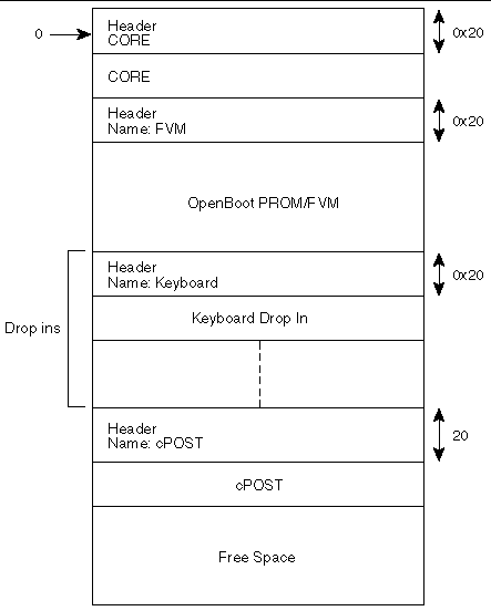
TABLE 6-5 lists the firmware CORE commands that are run from the monitor.
ASM support is added at the OpenBoot PROM level. The ASM monitors the CPU temperature. The CPU warning, critical and shutdown temperature default limits are set at 60° C, 65° C and 70° C, respectively. For more information on ASM Warning, Critical and Shutdown temperature parameter settings, refer to the Netra CP2000 and CP2100 Series CompactPCI Boards Programming Guide for Solaris Operating Environment (816-0854-xx).
The following NVRAM variables are added in OpenBoot PROM for ASM:
1) NVRAM variable name: env-monitor?
Function :enables or disables environment monitoring at OBP.
Data type :string
Valid values :disabled or enable
Default value :disable
OBP Usage :OK setenv env-monitor? enable
2) NVRAM variable name :warning-temperature
Function :sets the cpu warning temperature threshold
Data type :byte
Unit :Decimal
Default value :60
OBP Usage :ok setenv warning-temperature <temperature-value>
3) NVRAM variable name :shutdown-temperature
Function :sets the cpu shutdown temperature threshold
Data type :byte
Unit :Decimal
Default value :70
OBP Usage :ok setenv shutdown-temperature <temperature-value>
CAUTION: User should exercise caution while setting the above two parameters.
Setting these values too high leaves the system un-protected against system
over-heat.
WARNING: Temperature response at OBP When cpu temperature reaches
"warning-temperature", the following message is spit out at ok prompt
at a regular interval:
.......
Temperature sensor #2 has threshold event of
<<< WARNING!!! Crossing Warning temperature threshold >>>
The current threshold setting is: 18
The current temperature is : 28
.......
Critical Temperature response at OBP
Sensor in IPMB Addr 20 has event ===
Temperature sensor #2 has threshold event of
<<< !!! ALERT!!! Crossing Critical temperature threshold >>>
The current threshold setting is: 20 degreeC
The current temperature is : 28 degreeC
Shutdown Temperature response at OBP
When cpu temperature reaches "warning-temperature", the following message is displayed at ok prompt at a regular interval,
...........
Temperature sensor #2 has threshold event of
<<< !!! ALERT!!! Upper Critical - going high >>>
The current threshold setting is: 65
The current temperature is : 66
...........
show-sensor command at OBP
--------------------------
The "show-sensor" command at OBP displays the readings of all the temperature sensors on the board.
If the installed version is not current, update the OpenBoot PROM before continuing. The third character group (X) in OpenBoot PROM is the revision number.
To determine the installed OpenBoot PROM version, type the .version command at the ok prompt. For an example, the firmware version in the output below is the OpenBoot PROM version:

Type the prtconf command at the machine_name prompt:

To update the binary image for both system flash and user flash, OpenBoot PROM is always stored in system flash. User flashes are provided for you to store your own application code or a backup copy of OpenBoot PROM.
|
Note - The Netra CP2140 board does not support booting the Solaris operating environment from a user flash EPROM device. |
Use SMC Config block to select booting mode, either from system flash or from user flash.
The following example shows how to select OpenBoot PROM booting mode using the setting in the SMC config block:
ok printsmcenv
config-version : 3
backplane-type : 1
reset-mode : 11
sir-xir-enable : 2
byte5 : 0
chassis-type : 0
flash-device : 8 (userflash mode )
byte8 : 0
ha-signal-handler : 0
poweron-vector : 0
ipmi-checksum-ctlr : 0
byteC : 0
byteD : 0
byteE : 0
byteF : 0
byte10 : 0
ok
ok setsmcenv flash-device h# c
ok printsmcenv
config-version : 3
backplane-type : 1
reset-mode : 11
sir-xir-enable : 2
byte5 : 0
chassis-type : 0
flash-device : c (userflash mode c is equivalent
to sysflash mode)
byte8 : 0
ha-signal-handler : 0
poweron-vector : 0
ipmi-checksum-ctlr : 0
byteC : 0
byteD : 0
byteE : 0
byteF : 0
byte10 : 0
ok
The command format is flash-update file-path flashtype.
ok flash-update file-path systemprom <---- to update system flash
ok flash-update file-path userprom1 <---- to update user flash1
ok flash-update file-path userprom2 <---- to update user flash2
In the absence of flashtype, the OpenBoot PROM updates OpenBoot PROM in whatever flash has the address:
/pci@1f,0/pci@1,1/ebus@1/flashprom@10,0
For example, in sysflash mode, the system flash is updated. In the user flash mode, the user flash #1 is updated.
If a combined SPARC and SMC binary file is provided to the flash-update command then it updates SMC as well as the SPARC firmware. Use the regular flash-update command to update the combined binary and follow the syntax of the flash-update command with the full file path of the combined binary.
This firmware can only be upgraded when operating at the OpenBoot PROM level, that is, at the ok prompt. The following procedure gives the steps to update firmware on the target system.
1. Download the latest Netra CP2140 board host firmware binaries.
Download the latest CP2140 host firmware (OpenBoot PROM) and SMC firmware to your server. Contact your Field Application Engineer for help on how to download it.
2. Bring the system down to OpenBoot PROM level.
If your Netra CP2140 host is currently running Solaris software, become superuser and type the following command to halt the system:
$ shutdown -i0 -g0 -y
$ init 0
3. Check the firmware revision.
Check the current firmware revision on the target system by typing:
ok .version
See Section 6.6.1, From OpenBoot PROM for an example of the output of this command.
The Platform ID identifies the board ID. For example, if ID = 10 indicates the CP2140.
For each release, there must be compatible revision numbers for other components. To get the correct combination, refer to the latest release notes.
4. Disable autoboot; then reset.
Disable autoboot and reset the system using the following commands:
ok setenv auto-boot? false
ok reset-all
5. Flash update your firmware.
ok flash-update obp-file-path/obp-latest-binary
ok smc-flash-update smc-file-path/smc-latest-binary
If you have the combined SPARC and SMC binary file then use the following command:
ok flash-update obp-smc-file-path/obp-smc-combined-latest-binary
The system should automatically reset. If it does not, power cycle it.
6. Check the firmware revision.
Check the firmware revision by typing:
ok .version
The output appears as in the example in Step 3. Ensure that the version information shows up as expected. If not, repeat Step 1 through Step 6.
7. Enable autobooting and reset the system.
ok setenv auto-boot? true
and reset the system to boot the Solaris software:
ok reset-all
Contact your service personnel if you have any problems.
|
Note - Solaris scripts are also available to upgrade core OpenBoot PROM firmware. |
The following sequence enables you to boot up the correct OpenBoot PROM image.
1. You are logged in UserFlash Mode 8 with OpenBoot PROM image from User Flash #1, which has the following setup in SMC config block:
ok printsmcenv
config-version : 3
backplane-type : 1
reset-mode : 11
sir-xir-enable : 2
byte5 : 0
chassis-type : 0
flash-device : 8
byte8 : 0
ha-signal-handler : 0
poweron-vector : 0
ipmi-checksum-ctlr : 0
byteC : 0
byteD : 0
byteE : 0
byteF : 0
byte10 : 0
ok
2. Flash updates new OpenBoot PROM to system flash:
ok flash-update file-path systemprom
3. Change to system flash to boot up if you want to boot from it:
ok setsmcenv flash-device c
4. Power cycle the CP2140 system.
The new OpenBoot PROM boots up from the system flash.
SMC firmware is updated only from the OpenBoot PROM level. Follow these steps to update the SMC firmware:
1. Check with your Field Application Engineer.
2. Type the following command:
smc-flash-update filename
|
Note - The filename must be a valid binary or else the file cannot be read to complete the flash update. |
3. If a power failure occurs, or an error message displays, or you notice that the second binary is an F, then the flash update has failed.
The following example shows the binary breakdown:
4. You must now perform a code recovery of the SMC flash update in order for the code to work.
This section describes how to send and receive packets from one board to another board using the IPMI protocol. First, you must know how to set the IPMB address of each board.
The following steps show you how to calculate the Geographical Address bits:
1. Read Geographical Address bits.
ipmb_addr = 0xB0 + (GA - 1) * 2
ipmb_addr = 0xC4 + (GA - 10) * 2
3. For SBC, IPMB address is always 0x20.
Before sending the IPMI packet to the other board, you must set a bit in the global enable register inside SMC.
|
Note - All examples shown in this section are performed at the CORE level. |
To do this, send cmd 0x2F to the SMC (get_smc_global_enable).
It returns three bytes of data: The first byte is completion code, the other 2 bytes are global enable bits.
After you get the data, send the following packet to the SMC:
command 0x2E (set_smc_global_enables):
07 : Byte count
XX : Checksum
XX : Sequence number
18 : NetFN/LUN
2e : set_smc_global_enables
YY : Put back the first byte that you read earlier.
ZZ : Put back the 2nd byte that you read earlier, but modify bit 4 to 0.
Now you can send the IPMI packet through the send_message command. You must append this IPMI packet to the EBus packet header, plus the channel number, where 0 is IPMI channel, 1 is the interhost channel.
LL: Byte count
CS: Checksum
SN: Sequence number
18: NetFN/LUN
34: send_message command
00: Channel number, IPMI channel is 0, Interhost is 1.
Append the following IPMI packet to the header:
RA: Responder address, in this case this is the destination IPMB address.
NF: IPMI net function for the command that you want to send.
This MUST be shifted left by 2 bits, and ORed it with LUN, in this case we set it to 1.
CS: Checksum for the IPMI packet.
QA: Requester address. This is the IPMB address of the requester.
SN: Sequence number
CM: IPMI command
After this command is sent to the SMC, you will receive a response packet from the SMC.
|
Note - This is not the IPMI response packet; this is the SMC response packet indicating that it received the command. |
If the packet is received, the SMC responds with:
06: Byte count.
CS: Checksum.
SN: Sequence number
1C: Response NetFN number
34: send_message command.
00: OK.
After you retrieve that packet, you can send command 0x33 (get_message) in the following format
05: Byte count.
CS: Checksum.
SN: Sequence number
18: NetFN/LUN
33: get_message command
If the packet is received, the other board which is appended to the EBus packet header, responds with:
LL: Byte count
CS: Checksum
SN: Sequence number
1C: Response NetFN number
33: get message command
00: OK.
The IPMI response packet is appended to the packet header listed above. Source and destination IPMB addresses are exchanged in the response packet.
|
Note - In order to get the response packet from the other board properly with the get_message command, the sequence number expected must match the sequence number sent. |
Here is an example of the get_device_id command:
Send packet to read global enable bits
5 0 0 18 2f
You get the following response packet from the SMC:
8 0 0 1c 2f 0 0 14
Send packet to set global enable bits:
7 0 0 18 2e 0 4
Now you can send the IPMI packet to the other board so that it can read its device ID.
c 0 22 18 34 0 b6 19 0 20 22 1 bd
The sequence number in this case is set to 22 (this number is picked arbitrarily).
Net function for get_device_id command is 6, and we shift it 2 bits to the left, and ORed it with logical unit number 1. Therefore it becomes 19. The b6 is the address of the board from which the device ID is requested.
Since this packet is being sent from the SBC, 20 is put as the requester IPMB address and 1 is the get_device_id command for Netfunction 6 (Application).
If everything goes well, SMC sends the following response packet first:
6 0 22 1c 34 0
You can read the device ID packet of the other board, by issuing a get_message command, the packet looks like this:
5 0 22 18 33
If the data is not available, the following response packet is received from the SMC:
6 0 22 1c 33 80
Completion code 80 indicates that data is not available.
Otherwise, you will get the following response packet from the SMC:
1d 0 22 1c 33 0 ......
followed by the IPMI response packet from the other board, with the requester and responder addresses swapped from the original IPMI packet header.
TABLE 6-6 shows an example of a chassis configuration.
|
Note - On the first slot, the SBC is assigned an IPMB address of 0x20, not 0xB0. If the second slot becomes SBC, then the IPMB address becomes 0x20, not 0xB2. |
To send an IPMI packet to other boards, make sure that you include the correct checksum data in the IPMI packet.
TABLE 6-7 shows what an IPMI packet looks like.
To calculate the checksum, add all the data involved for that particular checksum entry, then use this formula:
The checksum arithmetic that is done is module 256 since only one byte is allocated for each checksum. By performing this calculation, once all the data entries for the checksum have been added and the result is added to that checksum, you get a result of 0.
The examples below show how to send a packet at the OpenBoot PROM interface at the ok prompt. At the OpenBoot PROM level, you do not have to include all EBus packet header data, making the process simple.
Type the following commands at the ok prompt as shown below:
ok dev hsc
ok showstack
ok words
The showstack command enables you to see the value of the returned data. The words command lists all the commands that are supported.
Now you are ready to send the packets.
The generic format is as follows:
ok ipmi_packet CH BC 34 execute-smc-cmd
Reviewers: Is ipmi_packet CH BC supposed to be variables and 34 execute-smc-cmd the literal command?
Where the ipmi_packet is the data in the IPMI packet, CH is the channel number and BC is the byte count.
|
Note - The IPMI packet data is entered backwards at the ok prompt. |
In this example, the get_device_id_command is used. B6 is the destination address or the responder, and 20 is the source address, or the requester. The command for get_device_id is 1 and the NetFn data field in this case is 19 (after it has been adjusted/shifted 2 bits to the left and ORed with 1). The sequence number is set to 22 in this case.
The IMPI packet looks like this:
b6 19 0 20 22 1 > byte count = 6
The channel number is 0 indicating that this is an IPMI channel.
The total byte count is 6 + 1 (the channel number) = 7.
ok 1 22 20 0 19 b6 0 7 34 execute-smc-cmd
if everything works as planned, you get the following message:
0 ok
At this point, you can issue a clear command to clear the stack.
You see the following message:
0 ok clear
ok
Now you are ready to issue command 33 to retrieve the response packet from the other board.
ok 0 33 execute-smc-cmd
If everything works as planned, you receive the following message:
.....ipmi_response_packet....ok
You also receive the EBus response data appended to the ipmi_response_packet. In this case, it is 0.
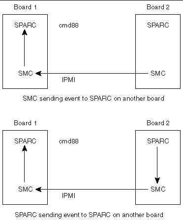
An event is a packet of information in a fixed format which is sent by the SMC on one board to another board through IPMI. The events are usually generated by the SMC and they go to another board's SMC, which sends it to the local SPARC.
But the event can also be generated by the SPARC wherein it sends the event packet to its SMC which sends the packet to another board. FIGURE 6-3 shows the host-to-host communication.
There is a fixed packet for any event to be sent. That packet is as follows:
evm_rev // Revision number
sensor_type
sensor_number
event_type_dir // dir => assertion/deasserion event..
event_data1
event_data2
event_data3
The packet formation depends on the sensor class and value. For example, if there is a temperature sensor, where the monitor task detects the temperature value higher than the threshold value, the packet might look like the following:
evm_rev = 0x03; // for current specs it is 0x03
sensor_type = TEMPERATURE_SENSOR; // sensor 0x01,Table 30.3
sensor_number = 0xe; // Sensor # assigned to a sensor.
event_type_dir = 0x01; // implies Threshold based sensor,Table 30.1
event_data1 = 0x59; // Implies that in event_data2 we have
// current temp value and in event_data3 we
// have threhold value which triggered the
// event. see table 17.5 IPMI specs
event_data2 = temp_sensor_ds1721.temp; // current temp value.
event_data3 = temp_sensor_ds1721.high_temp; // threshold value.
Thus, the values specified in the variables change depending upon the event type.
For detailed explanation of these variables, refer to IPMI Intelligent Platform Management Interface Specification (A00328-xxx).
All events are sent to the current event receiver. An event receiver is the address of the board which is bound to receive the events. By default, the event receiver is the BMC address 20 for all the SAT boards. However, any board can set itself or any other board as event receiver for other boards.
For example, a board at address 0xb6 can send IPMI command set_event_receiver to a board at address 0xba asking it to set address 0xb2 as its event receiver, so that now all the events from satellite at address 0xba goes to address b2. Similarly, the board at address 0xb6 could have asked 0xba to set 0xb6 itself as event receiver (which usually is the case).
The SMC sends the event to the currently set event receiver, without verifying whether that address is set correctly or not.
The event generation follows a particular protocol as described in the following test. As soon as an event condition is detected, the SMC creates the packet to be sent and sends an event packet to the event receiver. It then waits for the response from the event receiver to come until it times out. If the response does not come within that time, it sends the event packet again, with a different sequence number and again waits for the time out. This continues until retry count is exhausted.
During all this time, the state system is held in a state which indicates that the event is transmitted and no response has been received. So, if during this period, another event condition is generated, the event shall not be sent until the response to previously sent event has timed out.
The state changes to normal idle state if either it times out or a response to the event is received.
Refer to the IPMI Intelligent Platform Management Interface Specification (A00328-xxx) for more details.
When an event receiver gets an event packet, it does two things: First, it updates its mini system event log where it keeps the latest event from the SAT which is sending the event; second, it sends the event packet to the local SPARC as an asynchronous message through command 0x88.
This is a special case of event generation. Here the event is not sent to the current event receiver but to the address where the SPARC wants the event to be sent.
To send an event packet to another SPARC, the SPARC sends the packet through EBus command send event (command f6) to the local SMC. Also it sends the address where the event is to be sent. SMC extracts the packet and sends the event to this address.
The protocol to send the event to the receiver address remains the same. When the receiver gets the event packet, it sends the packet to local SPARC through command 0x88.
The EBus packet for command 0xf6 looks similar to CODE EXAMPLE 6-3:
LEN D CHK 0 SEQ Sequence Number NETFN/RSLUN 0X18 CMD 0XF6 IPMB ADDR EVM REV SENSOR TYPE SENSOR NUMBER EVENT DIR EVENT DATA1 EVENT DATA2 EVENT DATA3 |
The response packet for this EBus command is as shown in CODE EXAMPLE 6-4:
LEN 5 CHK 0 SEQ Sequence number NETFN/RSLUN 0X1c CMD 0XF6 CC Completion Code |
If the completion code is 0xC0, the SMC is waiting for the response to the previously sent event packet. If the completion code is 0, the event packet has been sent.
This document lists the features supported by this release (Release 3.8.9). A brief description is included for each command.
The list is sorted by the opcode number:
1. Cmd. 0x22, reset watchdog timer.
2. Cmd. 0x24, set watchdog timer.
3. Cmd. 0x25, get watchdog timer.
4. Cmd. 0x2e, set SMC global enables.
5. Cmd. 0x2f, get SMC global enables.
8. Cmd. 0x52, master write-read I2C
9. Cmd. 0x55, get geographical address.
10. Cmd. 0x60, select memory device.
11. Cmd. 0x63, write selected memory device.
12. Cmd. 0x65, erase selected memory device.
13. Cmd. 0x6f, get firmware version.
15. Cmd. 0x71, get role information.
16. Cmd. 0x83, notify SMC of host health.
17. Cmd. 0x84, turn blue, or red LED on/off.
18. Cmd. 0x87, enum notification.
|
Note - The host does not send this command. This is an asynchronous command which means it comes only from the SMC. |
19. Cmd. 0x88, IPMI response message notification.
|
Note - The host does not send this command. This is an asynchronous command which means it comes only from the SMC. |
20. Cmd. 0x8b, SMC local event.
|
Note - This is also an asynchronous command, only sent by the SMC. |
21. Cmd. 0x8c, get device table data.
This is used by the host to read device table information. The device table contains data of which slots are occupied, etc. Only the board that support IPMI is listed.
22. Cmd. 0xa0, get SMC self test results.
25. Cmd. 0xf4, get sensor event enable. This command is used to get the sensor event enable setting.
26. Cmd. 0xf5, set sensor event enable.
28. Cmd. 0xf8, get configuration block.
This is used to read the configuration data in the I2C EEPROM device.
29. Cmd. 0xf9, set configuration block.
The data is used for power up sequence.
|
Note - In order to take effect, after the new data is written, the board must be power cycled. |
31. Cmd. 0xfc, get sensor reading.
32. Cmd. 0xfd, get sensor threshold
33. Cmd. 0xfe, set sensor threshold.
The firmware contains a comprehensive set of hardware diagnostic modules that provide tests for most situations. FIGURE 6-1, shows the control-flow relationship of the diagnostic modules with the system firmware. The Sun Validation Test Suite (SunVTS ) package can be executed from within the Solaris software if more tests are required.
The Firmware diagnostic modules are:
The firmware diagnostics cover address and data bits on all system buses and exercise the function of the major hardware resources on the board.
Diagnostics can be performed at OpenBoot PROM level by using the obdiag command, or by typing individual test commands at the ok prompt. These test suites are similar to those in earlier OpenBoot PROM versions but they are comprised of dropins that can be placed by the user.
The user interface in terms of running POST at minimum or maximum remains the same. BPOST is embedded within Firmware CORE and is executed when the OpenBoot PROM environment variable, diag-switch? is set to true and
diag-level set to min. Similarly CPOST (and EPOST if it is present) is executed when diag-level is set to max. The permutations are shown in TABLE 6-4.
CPOST, and Extended POST are clients of Firmware CORE.
BPOST is integrated into Firmware CORE. It can provide on-demand diagnostic services in response to:
The first part of BPOST executes from flash memory. It is designed to validate enough of the system resources to be able to run Firmware CORE in main memory (System RAM). If this test phase is passed, BPOST is also copied into system RAM.
The part of BPOST executed from flash includes basic tests for the items:
The second part is performed after Firmware CORE is copied into main RAM. This part of BASIC POST executed from RAM includes:
Comprehensive POST (CPOST) is a client of Firmware CORE. It is a dropin module invoked by Firmware CORE and contains enhanced diagnostics for the CPU and on-board devices.
The execution of CPOST is optional and can be selectively controlled by an environment variable--see TABLE 6-4. CPOST runs after BPOST. To run CPOST, set the environment variables diag-switch to true and diag-level set to max.
Execution passes to EPOST (if it exists) or undergoes a software reset which sends it back to Firmware CORE. From this point, execution enters OpenBoot PROM (since diagnostics are only executed at power on reset).
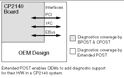
Extended POST enables OEMs to provide additional firmware diagnostics for their hardware within a CP2140-based system. Extended POST is a dropin module invoked by CPOST and is also a client of Firmware CORE from which it uses trap- based services.
The conditions for execution of EPOST are:
Before passing control to EPOST, CPOST creates a list of pointers of vital functions and passes these to EPOST.
The OpenBoot PROM onboard diagnostics reside in the OpenBoot PROM dropin.
To execute the OpenBoot PROM onboard diagnostics, the system must be at the ok prompt. The OpenBoot PROM onboard diagnostics comprise:
The OpenBoot Diagnostics are an enhancement of the traditional system tests. They reside in Forth script in a dropin and are invoked with an interactive tool started from the ok prompt.
When OpenBoot Diagnostics is started, the OpenBoot Diagnostics menu shown below is displayed.
|
Commands: test test-all except help what printenvs setenv versions exit |
An example of the test-all OpenBoot Diagnostics command follows:
ok obdiagobdiag> test-allHit the spacebar to interrupt testingTesting /pci@1f,0/pci@1,1/ebus@1 .....................................passed
Testing /pci@1f,0/pci@1,1/ebus@3 .....................................passed
Testing /pci@1f,0/pci@1,1/ebus@1/fdthree@14,3203f0 Testing
floppy disk system. A formatted disk should be in the drive.
Recalibrate failed. The floppy drive is either missing,improperly
connected, or defective.
Selftest at /pci@1f,0/pci@1,1/ebus@1/fdthree@14,3203f0 (return:-1) ...failed
Testing /pci@1f,0/pci@1,1/ebus@1/flashprom@10,0 ......................passed
Testing /pci@1f,0/pci@1,1/ebus@1/flashprom@10,400000 .................passed
Testing /pci@1f,0/pci@1,1/ebus@1/flashprom@10,800000 .................passed
Testing /pci@1f,0/pci@1,1/network@1,1 ................................passed
Testing /pci@1f,0/pci@1,1/network@3,1 ................................passed
Testing /pci@1f,0/pci@1,1/scsi@2 .....................................passed
Testing /pci@1f,0/pci@1,1/scsi@2,1 ...................................passed
Testing /pci@1f,0/pci@1,1/usb@1,3 ....................................passed
Testing /pci@1f,0/pci@1,1/usb@3,3 ....................................passed
Hit any key to return to the main menu
| Netra CP2140 Technical Reference and Installation Manual | 816-4908-10 |
Copyright © 2002, Sun Microsystems, Inc. All rights reserved.
