| Sun Fire V445 Server Administration Guide
|
   
|
This appendix provides reference information about the system back panel ports and pin assignments.
Topics covered in this appendix include:
Reference for the Serial Management Port Connector
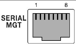
The serial management connector (labeled SERIAL MGT) is an RJ-45 connector located on the back panel. This port is the default connection to the system console.
Serial Management Connector Diagram

FIGURE A-1 Serial Management Connector Diagram
Serial Management Connector Signals
For Serial Management connector signals, see TABLE A-1.
TABLE A-1 Serial Management Connector Signals
|
Pin
|
Signal Description
|
Pin
|
Signal Description
|
|
1
|
Request to Send
|
5
|
Ground
|
|
2
|
Data Terminal Ready
|
6
|
Receive Data
|
|
3
|
Transmit Data
|
7
|
Data Set Ready
|
|
4
|
Ground
|
8
|
Clear to Send
|
Reference for the Network Management Port Connector
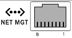
The network management connector (labeled NET MGT) is an RJ-45 connector located on the ALOM card and can be accessed from the back panel. This port needs to be configured prior to use.
Network Management Connector Diagram

FIGURE A-2 Network Management Connector Diagram
Network Management Connector Signals
For Network Management connector signals, see TABLE A-2.
TABLE A-2 Network Management Connector Signals
|
Pin
|
Signal Description
|
Pin
|
Signal Description
|
|
1
|
Transmit Data +
|
5
|
Common Mode Termination
|
|
2
|
Transmit Data -
|
6
|
Receive Data -
|
|
3
|
Receive Data +
|
7
|
Common Mode Termination
|
|
4
|
Common Mode Termination
|
8
|
Common Mode Termination
|
Reference for the Serial Port Connector
The serial port connector (TTYB) is a DB-9 connector that can be accessed from the back panel.
Serial Port Connector Diagram

FIGURE A-3 Serial Port Connector Diagram
Serial Port Connector Signals
For serial port connector signals, see TABLE A-3.TABLE A-3
TABLE A-3 Serial Port Connector Signals
|
Pin
|
Signal Description
|
Pin
|
Signal Description
|
|
1
|
Data Carrier Detect
|
6
|
Data Set Ready
|
|
2
|
Receive Data
|
7
|
Request to Send
|
|
3
|
Transmit Data
|
8
|
Clear to Send
|
|
4
|
Data Terminal Ready
|
9
|
Ring Indicate
|
|
5
|
Ground
|
|
|
Reference for the USB Connectors
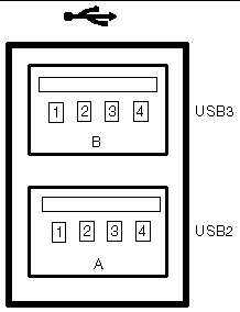
Two Universal Serial Bus (USB) ports are located on the motherboard in a double-stacked layout and can be accessed from the back panel.
USB Connector Diagram

FIGURE A-4 USB Connector Diagram
USB Connector Signals
For USB connector signals, see TABLE A-4.
TABLE A-4 USB Connector Signals
|
Pin
|
Signal Description
|
Pin
|
Signal Description
|
|
A1
|
+5 V (fused)
|
B1
|
+5 V (fused)
|
|
A2
|
USB0/1-
|
B2
|
USB2/3-
|
|
A3
|
USB0/1+
|
B3
|
USB2/3+
|
|
A4
|
Ground
|
B4
|
Ground
|
Reference for the Gigabit Ethernet Connectors
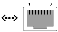
Four RJ-45 Gigabit Ethernet connectors (NET0, NET1, NET2, NET3) are located on the system motherboard and can be accessed from the back panel. The Ethernet interfaces operate at 10 Mbit/sec, 100 Mbit/sec, and 1000 Mbit/sec.
Gigabit Ethernet Connector Diagram

FIGURE A-5 Gigabit Ethernet Connector Diagram
Gigabit Ethernet Connector Signals
For Gigabit Ethernet connector signals, see TABLE A-5.
TABLE A-5 Gigabit Ethernet Connector Signals
|
Pin
|
Signal Description
|
Pin
|
Signal Description
|
|
1
|
Transmit/Receive Data 0 +
|
5
|
Transmit/Receive Data 2 -
|
|
2
|
Transmit/Receive Data 0 -
|
6
|
Transmit/Receive Data 1 -
|
|
3
|
Transmit/Receive Data 1 +
|
7
|
Transmit/Receive Data 3 +
|
|
4
|
Transmit/Receive Data 2 +
|
8
|
Transmit/Receive Data 3 -
|
| Sun Fire V445 Server Administration Guide
|
819-3741-13
|
   
|
Copyright © 2007, Sun Microsystems, Inc. All Rights Reserved.


