Connecting the Fiber Cable to the Interface Board and the I/O+ Board
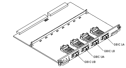
Internal FC-AL disk drives require an interface board (IB) to communicate via the I/O+ board. Figure 2-10 identifies the GBIC ports on the interface board, and Table 2-2 identifies the GBIC associated with each disk drive.
Figure 2-10 Interface Board
 Table 2-2 GBIC Controllers for Disk Drive Ports
|
Disk Drives |
Drive Port |
GBIC Name and Location |
|---|---|---|
|
0, 1, 2, 3 |
A |
GBIC LA (Lower bank) |
|
0, 1, 2, 3 |
B |
GBIC LB (Lower bank) |
|
4, 5, 6, 7 |
A |
GBIC UA (Upper bank) |
|
4, 5, 6, 7 |
B |
GBIC UB (Upper bank) |
Note -
Reserve disk bay 0 for the boot disk.
Wrapping the Fiber Cable on the Organizer
To ensure that the fiber optic cable minimum bend radius rule (1.0 inch) is observed, use this procedure to wrap the cable around the spool organizer:
-
Remove the two plastic caps that cover the cable connector on the GBIC module.
-
Remove the plastic cap covering the ends of the fiber cable.
-
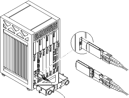
Connect one end of the fiber cable into the GBIC module installed on the interface board rear panel.
Use the IB diagram and GBIC controllers table above to identify the GBIC for the disk drive. Align the notch in the cable connector with the key notch in the GBIC module connector. See Figure 2-11.
Figure 2-11 Fiber Cable Ports on the Interface Board

-
Route the fiber cable down toward the bottom of the system, placing it through the left side restraints on the organizer.
-
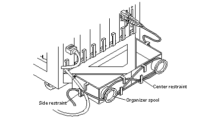
Wrap the cable around the fiber cable organizer spools (mounted on the system rear support bracket) in a "figure 8" pattern as follows:
Wrap the cable around the bottom of the left spool and then up and around the right spool, threading the cable through the center restraints on the organizer.
Thread the cable back through the center restraints, then down and around the left spool.
Figure 2-12 Fiber Cable in "Figure 8" Pattern

-
Repeat step 5 until the cable is the desired length, finishing on the right side. Thread the cable through the right side restraints and connect it to the I/O+ board.
- © 2010, Oracle Corporation and/or its affiliates
