| C H A P T E R 2 |
|
Installing a Sun Fire V490 Server Into a 2-Post Rack |
This chapter provides step-by-step instructions for installing a Sun Fire V490 server into a 2-post rack.
This chapter contains the following procedures and information:
|
Note - The steps are different if you are installing the server into a populated rack. See How to Install the Server Into a Populated Rack for instructions. |
You need one 2-post rackmounting kit for each Sun Fire V490 server you intend to install into a rack. You also need this document and the Rack Alignment template from the ship kit.
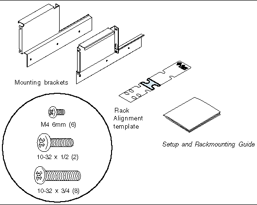
You will need the following tool when rackmounting the server:
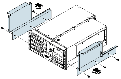
 Attach the mounting brackets to the chassis using three M4 screws for each bracket.
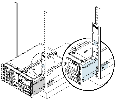
 Use the Rack Alignment template to locate and mark the holes for the mounting screws on each vertical rack rail. Allow five rack unit spaces (8.75 in/22.22 cm) per server.
To use the Rack Alignment template, complete these steps:
a. Place the Rack Alignment template over the vertical rack rail, with the side marked for 2-post rack installation facing out.
b. Rest the Rack Alignment template in the space where the server will be installed, lining up the bottom of the Rack Alignment template with the top of the server below. See next figure.
c. Adjust the Rack Alignment template so that the mounting hole is centered on a rack rail hole and mark that rail hol.
d. If you are installing the server into a space with fewer than seven rack units, you do not need to locate mounting holes or install mounting screws. You are ready to install the server into the rack. See How to Install the Server Into a Populated Rack.
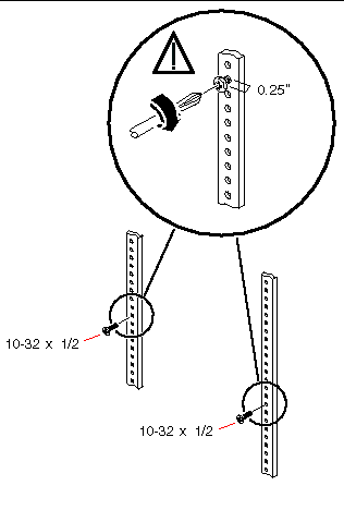
 Install one 10-32 x 1/2 screw on the left and one 10-32 x 1/2 screw on the right vertical mounting rails.
Use the holes you marked in the previous procedure. Do not fully tighten the screws until after you install the server. Leave a 0.25-inch (0.64-cm) gap between the head of each screw and the mounting rail.

|
Caution - The server is heavy. Two persons are required to move the server. |
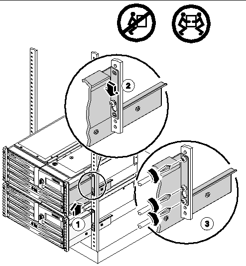
1. Lift the server (one person on each side of the server) and approach the rack with the back of the server facing the front of the rack.
2. Lift the server up and over the mounting screw on each vertical mounting rail so that the large hole clears the head of the screw.
Slide the server down so that the server rests on the mounting screws.
3. Use six 10-32 screws, two screws and the mounting screw on each side, to secure the server to the vertical mounting rails.
1. Attach the mounting brackets to the chassis using three M4 screws for each bracket. See How to Attach the Mounting Brackets to the Chassis for instructions.
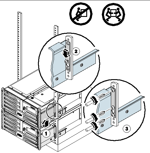
2. Slide the server into the open position in the rack.
Allow six rack unit spaces (10.5 in/26.67 cm) per server.
3. Using a Phillips No. 2 screwdriver, secure the top and bottom screws to the left and the right vertical mounting rails.

|
Caution - When installing or removing the server from a populated 2-post rack, be sure to support the weight of the server, so you do not damage the component installed below it in the rack. |
1. Connect the power cords and data cables to the server ports.
See the Sun Fire V490 Server Administration Guide for more information about external ports.
2. Connect the outlet plug of each power cord to the power sequencer in the cabinet, or to a grounded AC power outlet.
|
Note - For increased server redundancy, connect the power cords to separate circuits. |
3. Plug in the twisted-pair Ethernet (TPE) cable to the RJ-45 outlet to connect to your Ethernet network.
See your network administrator if you need more information about how to connect to your network.
4. Secure the server to the front vertical mounting rails using either four M6 screws or four 10-32 screws.
The next step is to connect the power cords and an Ethernet cable. See the Sun Fire V490 Server Administration Guide for information on back panel connector locations.
Copyright © 2005, Sun Microsystems, Inc. All Rights Reserved.