| C H A P T E R 2 |
|
Setting Up the System |
This chapter describes what you need to do to get the Sun Fire V890 server up and running. Where software is involved, this chapter explains some of what you need to do, and points you to the appropriate software manuals for the rest.
Tasks covered in this chapter include:
Other information covered in this chapter includes:
Standard features for the Sun Fire V890 server are installed at the factory. However, if you ordered options such as a monitor, these will be shipped to you separately.
Also, you should have received the Solaris Media Kit and documentation for all appropriate system software. Check that you have received everything you ordered.
Inspect the shipping carton for evidence of physical damage. If a shipping carton is damaged, request that the carrier's agent be present when the carton is opened. Keep all contents and packing material for the agent's inspection. Unpacking instructions are printed on the outside of the shipping carton.
Each step in this procedure refers you to a particular document or to a section of this guide for instructions. Complete each step in the order listed.
The Sun Fire V890 server is a general-purpose server, which you can use for many types of applications. Exactly how you set up your machine depends on what you want it to do.
This procedure is intended to be as "generic" as possible, so as to cover the needs of most sites. Even so, you will need to make certain decisions to complete the procedure:
For background information about network support, see About Network Interfaces.
For background information about internal storage array configuration options, see Mass Storage Subsystem Configuration.
Software included in the Solaris Media Kit or other software products may impose certain disk space or disk partitioning requirements. Refer to the documentation accompanying the software to determine those requirements.
|
Note - Refer to the Sun Fire V890 Server Product Notes for information about the software applications and Solaris OS for your system, before you install your Sun Fire V890 server. |
1. Verify that you have received all the parts of your system.
See About the Parts Shipped to You.
2. Set up the system in an appropriate environment.
The Sun Fire V890 server can be installed as a deskside or a rackmounted system. If you are installing the system in a rack, follow the instructions in the Sun Fire V890 Server Rackmounting Guide, which is available at http://www.sun.com/documentation.
|
Note - Do not install optional equipment into a system that you are rackmounting until after you have installed the system into the rack. |
If you are installing your server as a deskside system and need information about positioning the system in an appropriate environment, see the Site Planning Guide for Entry-Level Servers, which is included on the Sun Fire V890 Documentation CD.
3. Connect an AC power cord to each AC inlet at the back of each power supply. Connect the opposite end of each power cord to a grounded, dedicated AC power outlet.
Use the power cord supplied with the V890 server. The V890 server uses 200-240 VAC line input only.
|
Note - You must connect each power supply to a dedicated AC circuit. Consult your local electrical codes for any additional requirements. |
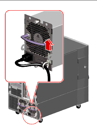
4. Attach a strain relief to each AC power cord.
The strain relief is a plastic tie-wrap and pedestal that is inserted into the rear panel of the server. Use these reliefs to manage the power cords after you have installed the cords into the AC inlets in the server.
To use a strain relief, press the tab to release the tie-wrap. Wrap the loose end of the tie-wrap around the AC power cord and thread the tie-wrap through the opening in the relief pedestal. Pull up the end of the tie-wrap to tighten it.
5. Install any optional components shipped with your system.
If you ordered options that are not factory-installed, see the Sun Fire V890 Server Service Manual for installation instructions.
|
Note - Do not install optional PCI cards into the system until after you have powered on and tested the system. |
6. If necessary, configure the serial port jumpers and connect any serial peripheral devices.
Two serial port jumpers located on the system I/O board are used to configure the system's serial ports to operate in compliance with the Electronics Industries Association EIA-423 or EIA-232D standards. The jumpers are factory-set for the EIA-423 standard, which is the default standard for North American users. Compliance with the EIA-232D standard is required for digital telecommunication in nations of the European Community. If you require EIA-232D compliance, see the Sun Fire V890 Server Service Manual and About Serial Port Jumpers. For information about serial port characteristics, see About the Serial Ports.

|
Caution - All internal jumper modifications must be performed only by qualified service personnel. |
You must set up a terminal or console in order to install system software and to view diagnostic messages.
At initial installation, you can either establish a tip connection from another server or attach an alphanumeric (ASCII) terminal to the serial port. See About Setting Up a Console.
|
Note - You cannot use RSC to perform the initial installation of the Solaris OS. You must install the operating system prior to setting up an RSC console. |
8. Prepare the network interface(s).
The Sun Fire V890 server provides two on-board Ethernet interfaces as part of the standard configuration--one Fast Ethernet interface and one Gigabit Ethernet interface. A variety of supported PCI cards can provide connections to additional Ethernet or other network types. For details about network interface options and configuration procedures, see the following sections:
9. Turn on power to your server.
See How to Power On the System.
When you power on the system for the first time, your system automatically runs power-on self-test (POST) and OpenBoot Diagnostics tests and displays the output on your console. The system also enables automatic system recovery (ASR).
10. Install and boot the Solaris Operating System.
See the installation instructions provided with your Solaris software. You should also consult the Sun Fire V890 Server Product Notes for information about the Solaris OS for your system.
11. Install and configure Remote System Control (RSC) software.
Install the Remote System Control (RSC) software, which is included in the Solaris Media Kit. You must manually install the RSC software before you can use RSC.
For information about configuring and using RSC, see the Sun Remote System Control (RSC) 2.2 User's Guide, which is included on the Sun Fire V890 Documentation CD.
|
Note - Once you install RSC software, you can configure the system to use RSC as the system console. For detailed instructions, see How to Redirect the System Console to RSC. |
12. (Optional) Load additional software from the Solaris Media Kit.
The Solaris Media Kit (sold separately) includes several CDs containing software to help you operate, configure, and administer your server. See the documentation provided with the Solaris Media Kit for a complete listing of included software and detailed installation instructions.
13. Check and update the FC-AL disk backplane firmware.
Installing the latest version of FC-AL backplane firmware ensures that the I/O system runs properly. Refer to the Sun Fire V890 Server Product Notes for information about checking and loading the latest backplane firmware.
14. Load any required and recommended patches for the system, if necessary.
Your system may be preinstalled with all required patches. Refer to the Sun Fire V890 Server Product Notes for information about patches. Check the SunSolve OnlineSM web site for any recent patches and service information about the system at http://sunsolve.sun.com.
15. Set any desired OpenBoot PROM configuration options.
You can control several aspects of system behavior through OpenBoot PROM commands and configuration variables. For additional details, see Configuring System Firmware.
16. Configure any additional network interfaces.
The Sun Fire V890 server provides two on-board Ethernet interfaces. Additional interfaces and connections are available by installing the appropriate PCI interface cards. See the Sun Fire V890 Server Service Manual, which is included on the Sun Fire V890 Documentation CD for installation instructions.
17. Load the electronic documentation from the Sun Fire V890 Documentation CD.
Directions for loading the documentation are printed in the booklet that accompanies the CD.
18. Turn the system keyswitch to the Locked position.
The Locked position is the recommended setting for day-to-day operations. This setting disables the system Power button, disables certain types of break commands that allow access to the ok prompt, and prevents unauthorized programming of the system's flash PROMs.
To install your server or to diagnose problems, you need some way to enter system commands and to view system output. There are four ways to do this.
1. Attach an alphanumeric (ASCII) character terminal to serial port A.
You can attach a simple terminal to serial port A. For instructions, see How to Attach an Alphanumeric Terminal.
2. Establish a tip connection from another Sun system.
For general information about establishing a tip connection, see the OpenBoot 4.x Command Reference Manual, which is available at: http://docs.sun.com, under Solaris on Sun Hardware. Refer to the Sun Fire V890 Server Product Notes for late-breaking details.
3. Install a local graphics console on your server.
The server is often shipped without a mouse, keyboard, monitor, or frame buffer for the display of graphics. To install a local graphics console on a server, a qualified service technician must install a graphics frame buffer card in a PCI slot, and attach a monitor, mouse, and keyboard to the appropriate rear panel ports. For detailed instructions, see How to Configure a Local Graphics Console.
|
Note - Power-on self-test (POST) messages are output to serial port A (ttya) or the RSC console only. |
4. Set up a Remote System Control (RSC) console.
RSC is a secure server management tool that lets you monitor and control your server over a serial port or a network connection. RSC provides convenient remote system administration for geographically distributed or physically inaccessible systems. For additional details, see About the System Controller Card and RSC Software and About Sun Remote System Control Software.
|
Note - You cannot use an RSC console to perform the initial installation of the Solaris OS. The operating system must be installed prior to setting up an RSC console. Once you install the operating system and the RSC software, you can configure the system to use RSC as the system console. For detailed instructions, see How to Redirect the System Console to RSC. |
If your server is configured without a local graphics console, you need to attach an alphanumeric (ASCII) terminal to the server in order to install the Solaris Operating System and to run diagnostic tests. Alternatively, you can install a local graphics console, create a tip connection from another Sun system, or set up an RSC console. For more information, see About Setting Up a Console.
|
Note - You cannot use an RSC console to perform the initial installation of the Solaris OS. The Solaris OS must be installed prior to setting up an RSC console. |
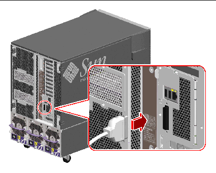
1. Connect a DB-25 null modem serial cable or a DB-25 serial cable and null modem adapter to the terminal's serial port.
2. Connect the opposite end of the cable to the system's serial port connector or to serial port A on the serial splitter cable.
3. Connect the terminal's power cable to an AC outlet.
4. Set the terminal to receive:
See the documentation accompanying your terminal for more information.
You can now issue system commands and view system messages. Continue with your installation or diagnostic procedure as needed.
If your server is configured without a local alphanumeric (ASCII) terminal, you need to install a local graphics console in order to install the Solaris Operating System and to run diagnostic tests. Alternatively, you can attach an alphanumeric terminal, create a tip connection from another Sun system, or set up an RSC console. For more information, see About Setting Up a Console.
|
Note - You cannot use an RSC console to perform the initial installation of the Solaris OS. The Solaris OS must be installed prior to setting up an RSC console. |
To install a local graphics console, you must have:
1. Install the graphics card into an appropriate PCI slot.
For information about PCI buses and slots, see About PCI Cards and Buses.
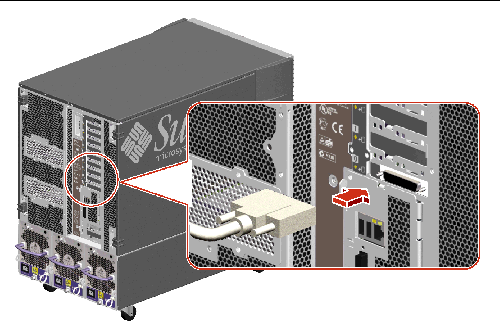
2. Attach the monitor's video cable to the graphic card's video port.
Tighten the thumbscrews to secure the connection.
3. Connect the monitor's power cord to an appropriate AC power outlet.
4. Attach the keyboard cable to one of the system's USB ports.
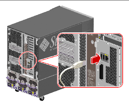
5. Attach the mouse cable to the system's remaining USB port, or to a USB port on the keyboard, if applicable.
You can now issue system commands and view system messages. Continue with your installation or diagnostic procedure as needed.
Do not use this power-on procedure if the operating system is already installed and you have just added a new internal option or external storage device. To power on the system after adding one of these options, see:

|
Caution - Before you power on the system, make sure that the front and side doors and all plastic outer panels are properly installed. |
1. Turn on power to any peripherals and external storage devices.
2. Turn on power to the alphanumeric terminal or local graphics console, if present.
3. Insert the system key into the front panel keyswitch and turn it to the Normal or Diagnostics position.
Normal position will enable the standard OpenBoot configuration for diagnostic testing as defined for your system.
Diagnostics position will enable service mode and a Sun prescribed level of diagnostic execution. Your system will automatically run maximum POST and OpenBoot Diagnostics tests and display the output.
For information about the standard default Open Boot configuration for diagnostic testing, see the OpenBoot PROM Enhancements for Diagnostic Operations Guide, which is included on the Sun Fire V890 Documentation CD.
See About the Status and Control Panel for more keyswitch information.
|
Note - The system will require a manual boot to the operating environment when the keyswitch is in the Diagnostics position. |
|
Note - For high availability environments, place the keyswitch in the Locked or Normal position. |
4. Press the Power button to the left of the keyswitch to power on the system.
5. Turn the keyswitch to the Locked position.
This prevents anyone from accidentally powering off the system.
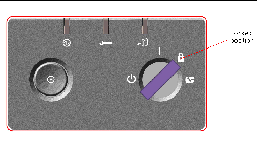
6. Remove the key from the keyswitch and keep it in a secure place.
The system's front panel LED indicators provide power-on status information. For more information about the system LEDs, see About the Status and Control Panel.
1. Notify users that the system will be powered down.
2. Back up the system files and data, if necessary.
3. Ensure that the front panel keyswitch is in the Normal or Diagnostics position.
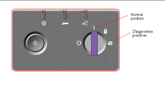
4. Press and release the Power button on the system front panel.
The system begins a graceful software system shutdown.
5. Wait for the front panel Power/OK LED to turn off.
6. Turn the keyswitch fully counterclockwise to the Forced Off position.
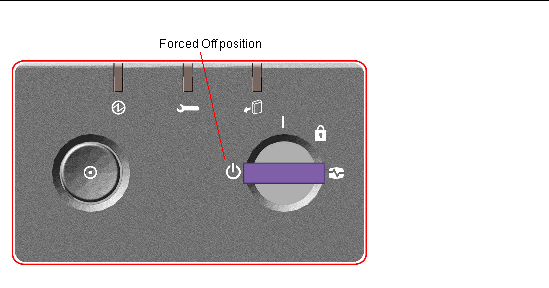
7. Remove the key from the keyswitch and keep it in a secure place.
After installing any new internal option or external storage device, you must perform a reconfiguration boot so that the operating system is able to recognize the newly installed device(s). In addition, if a qualified service technician removes a device and does not install a replacement device prior to rebooting the system, you must perform a reconfiguration boot in order for the operating system to recognize the configuration change. This requirement also applies to any component that is connected to the system's I2C bus, including memory modules, CPU/Memory boards, and power supplies.
This requirement does not apply to any component that is:

|
Caution - Before you power on the system, make sure that the front and side doors and all plastic outer panels are properly installed. |
You need a system console in order to issue software commands; see:
1. Turn on power to any peripherals and external storage devices.
Read the documentation supplied with the device for specific instructions.
2. Turn on power to the console.
3. Insert the system key into the front panel keyswitch and turn the keyswitch to the Normal position.
4. Press the Power button to the left of the keyswitch to power on the system.
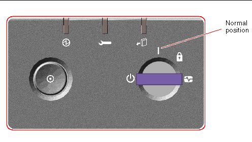
5. When the diagnostic tests are completed, the system banner is displayed on the system console followed by the ok prompt.
The system banner contains the Ethernet address and host ID.
The env-on command re-enables the OpenBoot environmental monitor, which may have been disabled as a result of the abort key sequence. The boot -r command rebuilds the device tree for the system, incorporating any newly installed options so that the operating system will recognize them.
7. Turn the keyswitch to the Locked position, remove the key, and keep it in a secure place.
This prevents anyone from accidentally powering off the system.
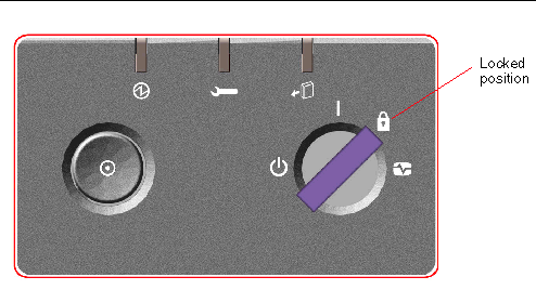
The system's front panel LED indicators provide power-on status information. For more information about the system LEDs, see About the Status and Control Panel.
If your system encounters a problem during system start-up, and the keyswitch is in the Normal position, try restarting the system with the keyswitch in the Diagnostics position to determine the source of the problem. Turn the front panel keyswitch to the Diagnostics position and power cycle the system.
Perform this procedure if, after installing the Solaris Operating System and the RSC software, you want to configure the system to use RSC as the system console. For more information about RSC, see About the System Controller Card and RSC Software and About Sun Remote System Control Software.
|
Note - When you configure the system to use RSC as the system console, power-on self-test (POST) diagnostic output is redirected to the RSC console. |
This procedure assumes that you are familiar with the OpenBoot firmware and that you know how to enter the OpenBoot environment. For more information about the OpenBoot firmware, see the OpenBoot 4.x Command Reference Manual, which is available at http://docs.sun.com, under Solaris on Sun Hardware. Refer also to the Sun Fire V890 Server Product Notes for late-breaking information.
1. Type the following commands at the system ok prompt:
The system permanently stores the new settings. The changes will take effect after the next reset.
2. To cause the changes to take effect immediately, reset the system, type:
The system permanently stores the changes and boots automatically if the OpenBoot variable auto-boot? is set to true (its default value).
|
Note - A power cycle will also cause the changes to take effect immediately. |
|
Note - In the unlikely event that the system controller card fails while the system console is directed to RSC, the system console will be unavailable. To recover from this situation, press the system Power button to initiate a graceful software shutdown. Then turn the keyswitch to the Diagnostics position or use the OpenBoot emergency procedure for resetting ID PROM configuration variables to their default values. See About OpenBoot Emergency Procedures. These measures will temporarily redirect the system console to the factory default device. If you are not installing a replacement system controller card right away, you may want to restore the local system console until a replacement card is available. See How to Restore the Local System Console. |
For instructions on how to use the system controller card and RSC software, see the Sun Remote System Control (RSC) User's Guide, which is included on the Sun Fire V890 Documentation CD.
Perform this procedure if your system is configured to use RSC as the system console and you need to redirect the system console to a local graphics console, alphanumeric terminal, or an established tip connection. For more information about RSC, see About the System Controller Card and RSC Software and About Sun Remote System Control Software.
This procedure assumes that you are familiar with the OpenBoot firmware and that you know how to enter the OpenBoot environment. For more information about the OpenBoot firmware, see the OpenBoot 4.x Command Reference Manual, which is available at: http://docs.sun.com, under Solaris on Sun Hardware. Refer also to the Sun Fire V890 Server Product Notes for late-breaking information.
1. Type the following commands at the system ok prompt:
The system permanently stores the new settings. The changes will take effect after the next reset.
2. To cause the changes to take effect immediately, type:
The system permanently stores the parameter changes and boots automatically if the OpenBoot variable auto-boot? is set to true (its default value).
|
Note - A power-cycle will also cause the changes to take effect immediately. |
Copyright © 2005, Sun Microsystems, Inc. All Rights Reserved.