| Netra 440 Server Service Manual
|
   
|
Identifying the Netra 440 Server FRUs and LEDs
|
This chapter contains the following sections:
For background information about the Netra 440 server and detailed instructions for installing, configuring, and administering the server, see:
- Netra 440 Server Installation Guide
- Netra 440 Server System Administration Guide
Locating Front Panel Components and LEDsFront Panel Components
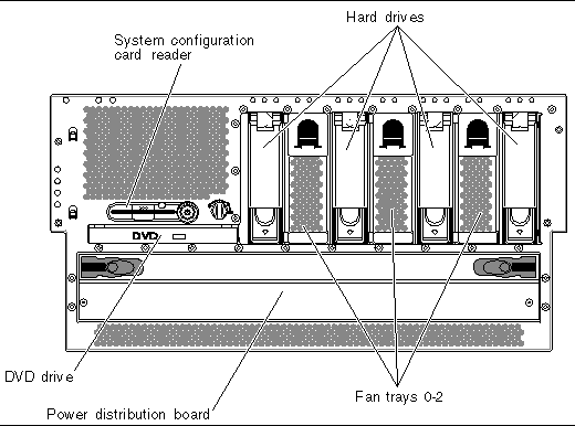
FIGURE 1-1 shows the system components that you can access from the front panel. In the figure, the system door is opened.
FIGURE 1-1 Front Panel Components
 [ D ]
[ D ]
For more detailed information about each of the front panel components, refer to the Netra 440 Server Product Overview.
TABLE 1-1 lists the front panel components The table indicates whether the components are hot-swappable or cold-swappable, and whether they can be removed from the front of the system or through the top of the system.
TABLE 1-1 Front Panel Components
|
|
Hot- or Cold-Swappable
|
Removal point
|
|
Component
|
Hot
|
Cold
|
Front
|
Top
|
|
System configuration card reader
|
|
•
|
|
•
|
|
Hard drives
|
•
|
|
•
|
|
|
DVD drive
|
|
•
|
•
|
|
|
Power distribution board
|
|
•
|
•
|
|
|
Fan trays 0-2
|
•
|
|
•
|
|
Front Panel LEDs
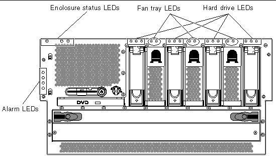
Several front panel LEDs provide general enclosure status, alert you to system problems, and help you to determine the location of system faults.
During system startup, the LEDs are toggled on and off to verify that each one is working correctly. LEDs located on the front panel work in conjunction with specific fault LEDs. For example, a fault in the power supply subsystem illuminates the power supply Service Required LED on the affected power supply, as well as the system Service Required LED. Since all front panel status LEDs are powered by the system's standby power source, fault LEDs remain lit for any fault condition that results in a system shutdown.
FIGURE 1-2 shows the LEDs that are accessible from the front. In the figure, the system door is opened.
FIGURE 1-2 Front Panel LEDs
 [ D ]
[ D ]
Enclosure Status LEDs
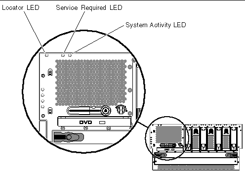
At the top left of the system as you look at its front are three enclosure status LEDs. The System Activity LED and the system Service Required LED provide a snapshot of the overall enclosure status. The Locator LED helps you to quickly locate a specific system even though it may be one of numerous systems in a room. The Locator LED is at the far left in the cluster, and is lit by command from the administrator.
FIGURE 1-3 Enclosure Status LEDs
 [ D ]
[ D ]
Each enclosure status LED has a corresponding LED on the back panel.
The enclosure status LEDs operate as described in the following table.
TABLE 1-2 Enclosure Status LEDs
|
Name
|
Icon
|
Description
|
|
Locator
|

|
This white LED is lit by a Solaris OS command or by ALOM software to locate a system. See the Netra 440 Server System Administration Guide for more information.
|
|
Service Required
|

|
This amber LED lights when system hardware or software has detected a system fault. This LED lights for any faults or failures detected in the following areas:
- Motherboard
- CPU/memory module
- DIMM
- Hard drive
- Fan trays
- Power supply
In addition to the system Service Required LED, other fault LEDs might also be lit, depending on the nature of the fault. If the system Service Required LED is lit, check the status of other fault LEDs on the front panel to determine the nature of the fault. See the Netra 440 Server Diagnostics and Troubleshooting Guide for more information.
|
|
System Activity
|

|
This green LED lights when the ALOM detects that the Solaris OS is running.
|
Hard Drive Status LEDs
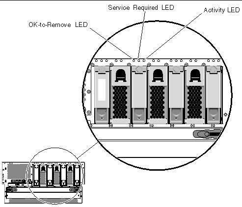
Each hard drive has its own status LEDs directly above the drive.
FIGURE 1-4 Hard Drive Status LEDs
 [ D ]
[ D ]
The following table describes the hard drive LEDs.
TABLE 1-3 Hard Drive LEDs
|
Name
|
Icon
|
Description
|
|
OK-to-Remove
|

|
This blue LED lights when the hard drive has been taken offline and is safe to remove from the system.
|
|
Service Required
|

|
Reserved for future use.
|
|
Activity
|

|
This green LED lights when the system is powered on and a hard drive is present in the monitored drive slot. This LED flashes slowly during the hard drive hot-swap procedure. It flashes rapidly when the hard drive is spinning up or down, or during read/write activity.
|
Fan Tray Status LEDs (0-2)
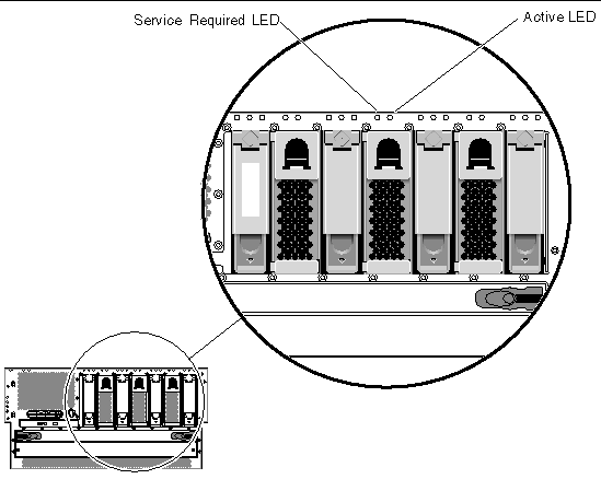
The fan tray LEDs are located behind the front cover, directly above each fan tray. Note that these LEDs give information only for fan trays 0-2; they do not give information on fan tray 3, located inside the system.
FIGURE 1-5 Fan Tray Status LEDs
 [ D ]
[ D ]
The following table describes the fan tray LEDs.
TABLE 1-4 Fan Tray LEDs
|
Name
|
|
Description
|
|
Service Required
|

|
This amber LED lights when there is a fault detected with the fan tray. Note that the Service Required LEDs on the front and back panels also light when this occurs.
|
|
Activity
|

|
This green LED lights when the fan tray is on and operating normally.
|
Alarm LEDs
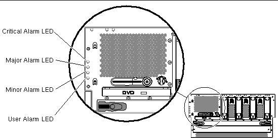
The alarm LEDs are located at the front of the system, along the left side of the front cover.
FIGURE 1-6 Alarm LEDs
 [ D ]
[ D ]
The dry contact alarm card has four LED status indicators that are supported by ALOM. Information about the alarm indicators and dry contact alarm states is provided in TABLE 1-5. For more information about alarm indicators, refer to the Sun Advanced Lights Out Manager Software User's Guide for the Netra 440 Server (817-5481-xx). For more information about an API to control the alarm indicators, refer to the Netra 440 Server System Administration Guide (817-3884-xx).
TABLE 1-5 Alarm Indicators and Dry Contact Alarm States
|
Indicator and Relay
Labels
|
Indicator Color
|
Application or Server State
|
Condition or Action
|
System Indicator State
|
Alarm Indicator State
|
Relay
NC
State
|
Relay
NO
State
|
Comments
|
|
Critical
(Alarm0)
|
Red
|
Server state (Power on/off and
Solaris OS functional/
not functional)
|
No power input.
|
Off
|
Off
|
Closed
|
Open
|
Default state
|
|
System power off.
|
Off
|
On
|
Closed
|
Open
|
Input power connected
|
|
System power turns on; Solaris OS not fully loaded.
|
Off
|
On
|
Closed
|
Open
|
Transient state
|
|
Solaris OS successfully loaded.
|
On
|
Off
|
Open
|
Closed
|
Normal operating state
|
|
Watchdog timeout.
|
Off
|
On
|
Closed
|
Open
|
Transient state; reboot Solaris OS
|
|
Solaris OS shutdown initiated by user.
|
Off
|
On
|
Closed
|
Open
|
Transient state
|
|
Lost input power.
|
Off
|
Off
|
Closed
|
Open
|
Default state
|
|
System power shutdown initiated by user.
|
Off
|
On
|
Closed
|
Open
|
Transient state
|
|
Application state
|
User sets Critical alarm on.
|
--
|
On
|
Closed
|
Open
|
Critical fault detected
|
|
User sets Critical alarm off.\
|
--
|
Off
|
Open
|
Closed
|
Critical fault cleared
|
|
Major
(Alarm1)
|
Red
|
Application state
|
User sets Major alarm on.\
|
--
|
On
|
Open
|
Closed
|
Major fault detected
|
|
User sets Major alarm off.\
|
--
|
Off
|
Closed
|
Open
|
Major fault cleared
|
|
Minor
(Alarm2)
|
Amber
|
Application state
|
User sets Minor alarm on.\
|
--
|
On
|
Open
|
Closed
|
Minor fault detected
|
|
User sets Minor alarm off.\
|
--
|
Off
|
Closed
|
Open
|
Minor fault cleared
|
|
User
(Alarm3)
|
Amber
|
Application state
|
User sets User alarm on.\
|
--
|
On
|
Open
|
Closed
|
User fault detected
|
|
User sets User alarm off.\
|
--
|
Off
|
Closed
|
Open
|
User fault cleared
|
In all cases when the user sets an alarm, a message is displayed on the console. For example, when the Critical alarm is set, the following message is displayed on the console:
Note that in some instances when the Critical alarm is set, the associated alarm indicator is not lit.
SC Alert: CRITICAL ALARM is set
|
Locating Back Panel Components and LEDsBack Panel Components
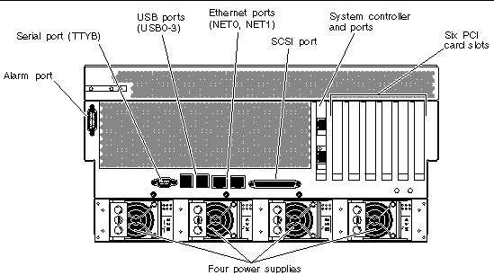
FIGURE 1-7 shows the system components that you can access from the back panel. Note that the power supplies shown in FIGURE 1-7 are for the DC-powered servers; the power supplies for the AC-powered servers would be in the same location as those shown in FIGURE 1-7, but would have different input connectors.
FIGURE 1-7 Back Panel Features
 [ D ]
[ D ]
TABLE 1-6 lists the rear panel components, and shows whether they are hot-swappable or cold-swappable, and whether they can be removed from the rear of the system or through the top of the system.
For more detailed information about each of the rear panel components, refer to the Netra 440 Server Product Overview (817-3881-xx).
TABLE 1-6 Back Panel Components
|
|
Hot- or Cold-Swappable
|
Removal Point
|
|
Component
|
Hot
|
Cold
|
Rear
|
Top
|
|
Alarm card and port
|
|
•
|
|
•
|
|
Motherboard with data ports
|
|
•
|
|
•
|
|
ALOM system controller and ports
|
|
•
|
|
•
|
|
PCI cards
|
|
•
|
|
•
|
|
Power supplies
|
•
|
|
•
|
|
Back Panel LEDs
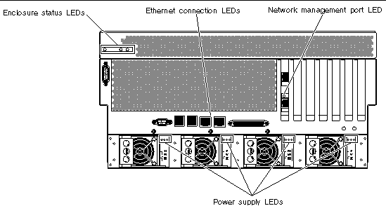
The back panel LEDs include the enclosure status LEDs, the Ethernet port LEDs, the power supply LEDs, and the SYSTEM controller card LED. The enclosure status LEDs are replicated from the front panel.
FIGURE 1-8 Back Panel LE Ds
 [ D ]
[ D ]
Ethernet Connection LEDs
A set of Ethernet LEDs is located on each Ethernet port. The Ethernet LEDs operate as described in the following table.
TABLE 1-7 Ethernet LEDs
|
Name
|
Description
|
|
Link/Activity
|
This green LED lights when a link is established at the particular port with its link partner, and blinks to indicate activity.
|
|
Speed
|
This amber LED lights when a Gigabit Ethernet connection is established, and is off when a 10/100-Mbps Ethernet connection is established.
|
Enclosure Status LEDs
The back panel enclosure status LEDs consist of the System Activity LED, the system Service Required LED, and the Locator LED. These LEDs are located in the top-left corner of the back panel, and operate as described in TABLE 1-2.
Network Management Port LED
The network management port has a Link LED that operates as described in TABLE 1-8.
TABLE 1-8 Network Management Port LED
|
Name
|
Description
|
|
Link
|
This green LED lights when an Ethernet connection is present.
|
Power Supply LEDs
There are three LEDs on each power supply. These LEDs operate as described in TABLE 1-9.
TABLE 1-9 Power Supply LEDs
|
Name
|
Icon
|
Description
|
|
OK-to-Remove
|

|
This blue LED lights when it is safe to remove the power supply from the system. This LED is controlled by the software only.
|
|
Service Required
|

|
This amber LED lights when the power supply's internal circuitry detects a fault. Note that the Service Required LEDs on the front and back panels also light when this occurs.
|
|
Power OK
|

|
This green LED lights when the power supply is in standby mode or when it is on and outputting regulated power within specified limits.
|
Back Panel Slots and Ports
The back panel provides access to the PCI slots, external ports, and Advanced Lights Out Manager (ALOM) card ports.
PCI Slots
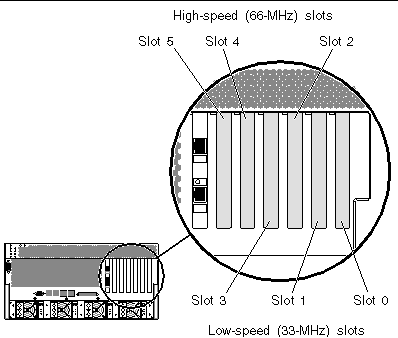
The Netra 440 server has three 33-MHz PCI slots and three 66-MHz PCI slots. These are labeled on the back panel. The Advanced Lights Out Manager (ALOM) card is located to the left of the PCI slots.
FIGURE 1-9 PCI Slots
External Ports
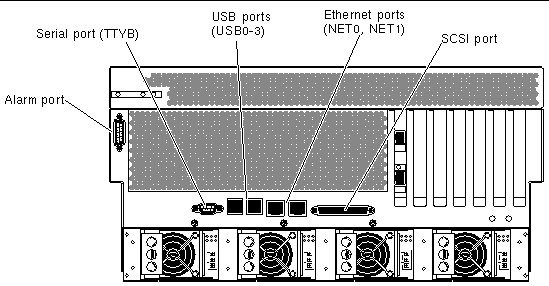
The Netra 440 server has eight external data ports on the back panel, which are described in TABLE 1-10.
FIGURE 1-10 Back Panel External Ports
 [ D ]
[ D ]
TABLE 1-10 Back Panel External Ports
|
Icon
|
Description
|
|
N/A
|
Alarm port. The system has one alarm port on the back panel, which uses a DB-15 connector.
|

|
Serial port. The system has one serial port (TTYB) on the back panel, which uses a DB-9 connector.
|

|
Universal Serial Bus (USB) ports. The system has four USB ports (USB0, USB1, USB2, USB3).
|

|
Ethernet ports. The system has two 10/100/1000-Mbps Ethernet ports (NET0, NET1).
|

|
SCSI connector. The system has one external SCSI 68-pin
SCSI connector.
|
ALOM System Controller Card External Ports
The Advanced Lights Out Manager (ALOM) system controller card has two connectors, which are described in TABLE 1-11.
FIGURE 1-11 ALOM System Controller Card Ports
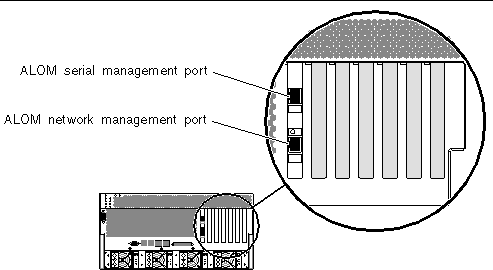
TABLE 1-11 ALOM External Ports
|
Icon
|
Description
|

|
Serial (RJ-45) port. This is the default serial management connection for the system.
|

|
Ethernet port. This port provides direct network access to the ALOM system controller card, when configured, and can access the ALOM prompt and system console output.
|
Locating Internal Components
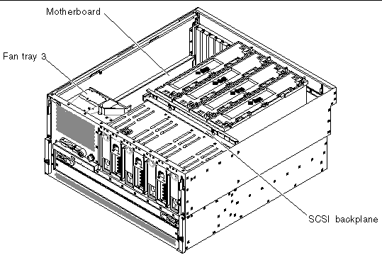
The illustration below shows the system's internal components from the top view.
FIGURE 1-12 Locating Internal Components
 [ D ]
[ D ]
TABLE 1-12 lists the internal components, and shows whether they are hot-swappable or cold-swappable, and whether they can be removed from the rear of the system or through the top of the system.
For more detailed information about each of the rear panel components, refer to the Netra 440 Server Product Overview.
TABLE 1-12 Internal Components
|
|
Hot- or Cold-Swappable
|
Removal Point
|
|
Component
|
Hot
|
Cold
|
Rear
|
Top
|
|
Fan tray 3
|
|
•
|
|
•
|
|
Motherboard
|
|
•
|
|
•
|
|
SCSI backplane
|
|
•
|
|
•
|
|
CPU modules
|
|
•
|
|
•
|

