| A P P E N D I X C |
|
Functional Description |
This appendix describes the inner workings of the Sun Ultra 45 or Ultra 25 workstation. Topic include:
This section provides an overview of the Sun Ultra 45 or Ultra 25 workstation.
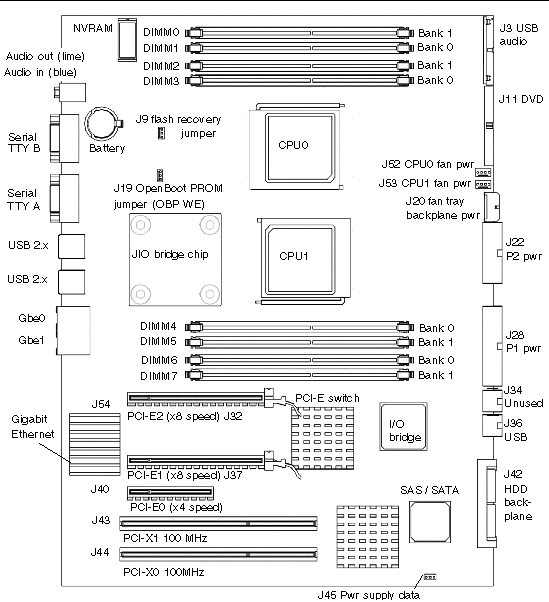
FIGURE C-1 shows the layout of the Sun Ultra 45 motherboard, including connector and jumper locations.
|
Note - The Sun Ultra 25 workstation motherboard has one CPU (CPU0) and one bank of four DIMM slots. Other aspects of the Sun Ultra 25 are the same as the Sun Ultra 45 workstation. |

FIGURE C-2 shows the Sun Ultra 45 workstation system diagram.

|
Note - The Sun Ultra 25 workstation motherboard has one CPU (CPU0) and one bank of four DIMM slots. Other aspects of the Sun Ultra 25 are the same as the Sun Ultra 45 workstation. |
This section describes some primary motherboard components.
TABLE C-1 describes the behavior of the Ethernet status LEDs.
This section describes more details about the motherboard and some components.
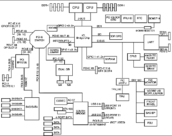
FIGURE C-3 shows the block diagram for the Sun Ultra 45 motherboard.
|
Note - The Sun Ultra 25 workstation motherboard has one CPU (CPU0) and one bank of four DIMM slots. Other aspects of the Sun Ultra 25 are the same as the Sun Ultra 45 workstation. |

The UltraSPARC IIIi processor is a high-performance, highly integrated superscalar processor. It is capable of sustained execution of four instructions per cycle, even with conditional branches and cache misses. Instructions are issued in program order to multiple functional units, and executed in parallel. Instructions from two basic blocks are issued in the same group to further increase the number of instructions executed per cycle.
The UltraSPARC IIIi CPU supports full implementation of the 64-bit SPARC-V9 architecture, a 64-bit virtual address space, and a 43-bit physical address space. The core instruction set includes graphics instructions that provide the most common operations used for two-dimensional image processing, two and three-dimensional graphics, image compression algorithms, and parallel operations on pixel data with 8- and 16-bit components.
The memory system consists of the memory control unit (MCU) in the CPU, and two physical banks (B0 and B1) of DDR-1 synchronous DRAM memory. Only registered DIMMS are supported.
Clock buffering with a PLL is provided on the DIMMs. Each physical bank consists of two 128-bit DDR-1 SDRAM DIMMs. These two DIMMs share an 8-byte data bus and an ECC data bus. Both physical banks share an address/control bus. Since each DIMM could be dual sided (upper and lower banks), there are maximum of four data loads per physical bank. The cache line is split across the two physical banks. Both banks are controlled by the memory controller.
A memory controller sends requests in the pipeline, using 16 memory banks in the Sun Ultra 45 when fully loaded, and 8 memory banks in the Sun Ultra 25 when fully loaded.

The Sun Ultra 45 or Ultra 25 workstation has two serial ports.
When powering off, the Sun Ultra 45 or Ultra 25 workstation sends a Break signal out the serial ports. This break could interfere with a workstation-controlled server if the server is operating through a Tip connection. Five solutions are available:
As superuser, open a terminal window and configure the alternate Break key sequence. Type:
To invoke a keyboard abort, type Return, ~, Ctrl-B.
|
Note - You must reconfigure the alternate Break key sequence after a server power cycle. |
The network terminal concentrator acts as a proxy between the Sun Ultra 45 or Ultra 25 workstation and the server under Tip control. The network terminal concentrator communicates with the host Sun Ultra 45 or Ultra 25 workstation through the Telnet protocol. If the workstation sends the BREAK signal, it is ignored by the network terminal concentrator. Additionally, the concentrator does not send the BREAK signal upon powering off.
This procedure configures the server to ignore the BREAK signal.
 As superuser, open a terminal window and disable the keyboard abort. Type:
 To re-enable keyboard abort, type:
|
Note - You must reconfigure the keyboard abort after a server power cycle. |
 To disable the Tip connection, turn the server key switch to the lock position.
This action prevents any serial communication with the server. To re-establish serial communications, turn the key to the unlock position.
1. As superuser, edit the /etc/default/kbd file.
3. Reinitialize the kbd drivers. Type:
Copyright © 2006, Sun Microsystems, Inc. All Rights Reserved.