| Sun StorEdge 3000 Family Installation, Operation, and Service Manual
|
   
|
This chapter describes the front-panel and back-panel LEDs, which give the clear status of the operation of all drives and modules. Topics covered in this chapter include:
6.1 LEDs When Array Is First Powered On
With the array powered on without the SCSI bus configuration cable installed while the array is not connected to a server, you should see the LED conditions described in TABLE 6-1 and TABLE 6-2.
TABLE 6-1 Front-Panel LED Status When Array Is First Powered On
|
Drive LEDs
|
Solid green
|
|
Chassis Ear LEDs
|
Solid green
|
TABLE 6-2 Back-Panel LED Status When Array Is First Powered On
|
I/O Module
|
|
|
ERROR LED
|
Blinking green (no bus configuration; invalid state)
|
|
TERM LED
|
Solid green (autotermination enabled)
|
|
|
Inactive (no bus configuration; invalid state)
|
|
Power/Fan Module
|
|
|
Power/Fan LEDs
|
Solid green
|
6.2 Front-Panel LEDs
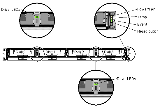
The drive LEDs are located between the rows of drives on the front panel (see the following figure). The system operation LEDs are located on the right ear of the chassis.
FIGURE 6-1 Front-Panel LEDs

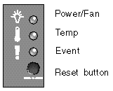
The following figure shows the front-panel LEDs and Reset button. Use the Reset button to silence an alarm. For alarm details, see Section 7.4, Silencing Audible Alarms.
FIGURE 6-2 Chassis Ear LEDs and Reset Button on Front Panel

The following table lists the front-panel LEDs.
TABLE 6-3 Front Panel LEDs
|
LED
|
LED Color
|
Description
|
|
Drive
|
Solid green
Blinking green
Solid amber
|
Good: Drive power-up and spin-up OK.
Good: Drive activity.
Failed: Drive failure.
|
|
Power (Light bulb icon)
Monitors the DC output voltage within tolerance specification. Overcurrent protection shutting down any voltage output displayed.
Voltage thresholds:
+5 VDC +/-.25 VDC
+12 VDC +/-.6 VDC
Current thresholds:
+5 VDC 20A
+12 VDC 12A
|
Solid green
Solid amber
|
Power supply good.
Failed: One or more output voltages out of range.
|
|
Temp (Thermometer icon)
Monitors the temperature level and indicates violations of internal temperature thresholds of 55°C (131°F) and 60°C (140°F).
|
Solid green
Solid amber
|
Good: Under temperature threshold of 55°C (131°F).
Failed: Temperature threshold equal to or over 55°C (131°F).
|
|
Event (Caution icon)
Indicates any abnormal or failure event.
|
Solid green
Solid amber
|
Normal operation.
Abnormal environment event.
|
|
Note - To test that the front-panel LEDs work, press and hold the Reset button for 5 seconds. All the LEDs should change from green to amber when you perform this test. Any LED that fails to light indicates a problem with the LED. When you release the Reset button, the LEDs return to their initial state.
|
6.2.1 Drive LED Status
The drive LED color changes based on array events. For example, when the Sun StorEdge CLI set led command is set to on, the drive LED changes from green to amber for the specified drive. For more information about set led, see Chapter 5. The following table lists the events that influence the drive LED status.
TABLE 6-4 Drive LED Status
|
LED Status
|
Event
|
Description
|
|
Solid green
|
No error
|
A drive is working as expected.
|
|
Blinking green
|
Drive activity
|
A drive is processing I/O.
|
|
Amber
|
Drive fault
|
A drive fails.
|
|
Amber
|
Identify
|
The Sun StorEdge CLI set led command is run.
|
6.3 Back-Panel LEDs
The back-panel LED colors indicate the conditions described in the following figures and tables. The following figure is the back-panel with LEDs.
FIGURE 6-3 Back-Panel LEDs

TABLE 6-5 Back-Panel Module LEDs
|
Module
|
LED Color
|
Status
|
|
Power supply/fan
Monitors the DC output voltage within tolerance specification. Overcurrent protection shutting down any voltage output will also be displayed.
Voltage thresholds:
+5 VDC +/-.25 VDC
+12 VDC +/-.6 VDC
Current Thresholds:
+5 VDC 20A
+12 VDC 12A
|
Solid green
Solid amber
Solid green
Solid amber
|
Power supply good.
Failed: one or more output voltages out of range.
Good fan: Over 900.
Faulty/failed: Under 900 RPM.
|
|
I/O module
TERM LEDs
ERROR LED
|
Solid green
Inactive LED
Blinking green
Solid amber
Inactive LED
|
Autotermination enabled.
Autotermination disabled.
Invalid single- or dual-cable configuration.
Failed I/O module.
Valid single- or split-bus configuration, and I/O module is good.
|

|
Caution - If you see a blinking green or amber LED, you might have an incorrect configuration or a failed component.
|
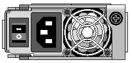
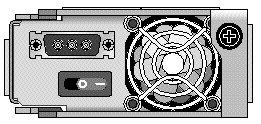
The AC and DC power supply and fan modules have a single LED.
FIGURE 6-4 AC Power Supply and Fan Module

FIGURE 6-5 DC Power Supply and Fan Module

The I/O modules for JBOD units have TERM and ERROR LEDs.
FIGURE 6-6 JBOD I/O Module

| Sun StorEdge 3000 Family Installation, Operation, and Service Manual
|
816-7956-15
|
   
|
Copyright © 2007, Dot Hill Systems Corporation. All rights reserved.


