| C H A P T E R 7 |
|
Maintaining and Troubleshooting Your Array |
This chapter describes troubleshooting procedures and error messages you can use to isolate configuration and hardware problems as well as maintenance procedures. This chapter covers the following topics:
To check front-panel and back-panel LEDs, see Chapter 6.
For more troubleshooting tips, refer to the Sun StorEdge 3120 SCSI Release Notes at:
http://www.sun.com/products-n-solutions/hardware/docs/Network_Storage_Solutions/Workgroup/
Monitoring conditions at different points within the array enables you to avoid problems before they occur. Cooling element, temperature, voltage, and power sensors are located at key points in the enclosure. The SCSI Accessed Fault-Tolerant Enclosure (SAF-TE) processor monitors the status of these sensors.
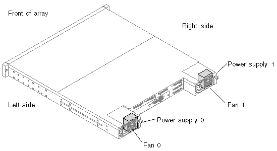
The following table describes the location of the enclosure devices from the back of the Sun StorEdge 3120 SCSI array orientation as shown in FIGURE 7-1.

The enclosure sensor locations and alarm conditions are described in the following table.
|
Disk slot identifier refers to the backplane FRU to which disks are connected |
||
Firmware upgrades are made available as patches that you can download from the Sun web site, located at:
Each patch applies to a particular type of firmware, including:
Each patch includes an associated README text file that provides detailed instructions about how to download and install that patch. Firmware downloads follow the same general steps:
Failed component alarm tones use Morse code dot and dash characters. The dot "." is a short tone sounding for one unit of time. The dash "-" is a long tone sounding for three units of time.
Alarms, also referred to as beep codes, are presented in a sequence, starting with the critical component failure alarm, which alerts you to a component problem or failure or a firmware mismatch. This alarm is then followed by alarms for whichever components or assemblies have failed. Once the beep code sequence is complete, it repeats. To understand the beep codes, listen to the sequence of codes until you can break down the sequence into its separate alarms. You can also check your software or firmware for alarms, error messages, or logs to isolate and understand the cause.
For example, in the case of a fan failure in a power supply, you might first hear the critical component failure alarm, followed by a power supply failure alarm from power supply 0 or power supply 1, followed by a fan failure event alarm, followed by an event alarm. This sequence will continue to repeat.
An audible alarm indicates that an environmental component in the array has failed. These error conditions and events are reported by event messages and event logs. Component failures are also indicated by LED activity on the array.
1. Use a paperclip to push the Reset button on the right ear of the array.
For details about where the Reset button is located, see Section 6.2, Front-Panel LEDs.
2. Check the front-panel and back-panel LEDs to determine the cause of the alarm.
For more information, see Chapter 6.
3. In Sun StorEdge Configuration Service, check the event log to determine the cause of the alarm.
Component event messages include but are not limited to the following terms:
For details about using Sun StorEdge Configuration Service to determine the cause of an alarm, see Section 5.2.2, Viewing Component and Alarm Characteristics.
When a problem is not otherwise reproducible, suspect hardware may need to be replaced. Always make only one change at a time and carefully monitor results. When possible, it is best to restore the original hardware before replacing another part to eliminate the introduction of additional unknown problem sources.
After hardware replacement, a problem can usually be considered solved if it does not resurface during a period equal to twice its original frequency of occurrence. For example, if a problem was occurring once a week on average before a potential fix was made, running two weeks without seeing the problem again suggests a successful fix took place.
Troubleshooting hardware problems is usually accomplished by a FRU isolation sequence that uses the process of elimination. Set up a minimal configuration that shows the problem and then replace elements in this order, testing after each replacement until the problem is solved:
Often you can also find out what causes a hardware problem by determining the elements that do not cause it. Start out by testing the smallest configuration that does work, and then keep adding components until a failure is detected.
To view error messages reported by JBODs, use any of the following:
For more information about replacing the chassis, see Section 8.7, Installing a JBOD Chassis FRU.

|
Caution - Back up the chassis data onto another storage device prior to replacing a disk drive to prevent any possible data loss. |
Before you begin troubleshooting JBODs, check the cables that connect the host to the JBOD. Look for bent pins, loose wires, loose cable shields, loose cable casing and any cables with 90 degree or more bends in them. If you find any of these problems, replace the cable.
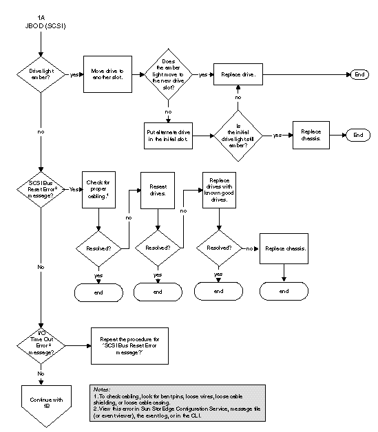
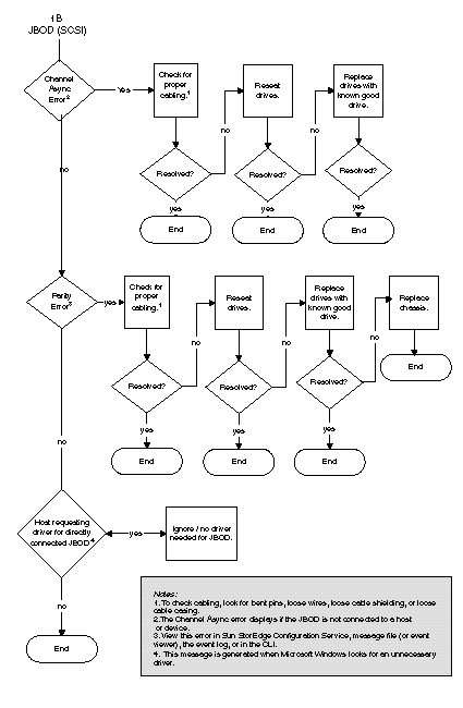
The FIGURE 7-2 flowchart provides troubleshooting procedures specifically for JBODs.
For an IBM AIX operating system, the event logs are not logged by default. You might need to change /etc/syslog.conf to enable it to write to a log file.
1. Modify /etc/syslog.conf to add the following line:
2. Make sure the file that is specified in the added line exists.
If it does not exist, you must create it. For example, in the above configuration, you would create a file named /tmp/syslog.
3. Change to /tmp/syslog and restart the syslog by typing:
Follow this sequence of general steps to isolate software and configuration issues.
|
Note - Look for storage-related messages in /var/adm/messages and identify any suspect Sun StorEdge 3120 SCSI arrays. |
1. Check the Sun StorEdge Configuration Service Console for alerts or messages.
For more information, see Chapter 6.
3. In Sun StorEdge CLI, run the show enclosure-status command.
For more information, see Section 5.4, Monitoring with the Sun StorEdge CLI.
4. Check revisions of software package, patches, and hardware.
5. Verify the correct device file paths.
6. Check any related software, configuration, or startup files for recent changes.
7. Search SunSolve Online for any known related bugs and problems at:
http://sunsolve.Sun.COM.
If you attach a JBOD array directly to a host server and do not see the drives on the host server, check that the cabling is correct and that there is proper termination. See the special cabling procedures in Section 4.6, Connecting Sun StorEdge 3120 SCSI Arrays to Hosts.
If the JBOD cabling is correct and the drives are still not visible, run the devfsadm utility to rescan the drives. The new disks can be seen when you perform the format command.
If the drives are still not visible, reboot the host(s) with the reboot -- -r command so that the drives are visible to the host.
Before beginning this procedure, make sure that you are using a supported SCSI host bus adapter (HBA) such as an Adaptec 39160. Refer to the Release Notes for your array for current information about which HBAs are supported.
Also make sure that you are using a supported driver for your HBA. For the Adaptec 39160, use FMS V4.0a or later.
1. Boot your system and verify that the host bus adapter (HBA) basic input/output system (BIOS) recognizes the new SCSI device.
|
Note - While your system is starting up, you should see the new SCSI device. |
2. If a Found New Hardware Wizard is displayed, click Cancel.
You are now ready to format your new device.
3. Open the Disk Management folder.
a. Right-click the My Computer icon and choose Manage.
b. Select the Disk Management folder.
c. If a Write Signature and Upgrade Disk Wizard is displayed, click Cancel.
A "Connecting to Logical Disk Manager Server" status message is displayed.
4. Select the new device when it is displayed.
5. Right-click in the Unallocated partition of the device and choose Create Partition.
A Create Partition Wizard is displayed.
7. Choose Primary partition and click Next.
8. Specify the amount of disk space to use or accept the default value, and click Next.
9. Assign a drive letter and click Next.
10. Choose Format this partition with the following settings.
a. Specify NTFS as the File system to use.
b. Make sure the Perform a Quick Format checkbox is checked.
A confirmation dialog box displays the settings you have specified.
The new partition is formatted and the formatted partition is identified as NTFS in the Computer Management window.
12. Repeat these steps for any other new partitions and devices you want to format.
When booting the server, watch for the host bus adapter (HBA) card BIOS message line to display onscreen and then press the proper sequence of keys in order to get into the HBA BIOS: Key strokes for SCSI Adaptec cards = <Ctrl><A>.
The key strokes are listed onscreen when the adapter is initializing. After you enter the Adaptec HBA BIOS with <Ctrl><A>, perform the following steps.
1. Highlight Configure/View Host Adapter Settings and press Return.
2. Go to Advanced Configuration Options and press Return.
3. Go to Host Adapter BIOS and press Return.
a. Select disabled:scan bus if this is not going to be a bootable device.
b. If it is going to be bootable device, select the default Enabled. The * represents the default setting.
4. Press Esc until you return to the main options screen where Configure/View Host Adapter Settings was located.
5. Select SCSI Disk Utilities and press Return.
The BIOS will now scan the SCSI card for any SCSI devices attached to the HBA. You will see the HBA's SCSI ID as well as any other SCSI devices attached to the HBA. If you only see the HBA's SCSI ID, then something is not correct with the configuration on the SCSI attached device, or the cable between the HBA and the SCSI device is bad or not attached.
6. If you are satisfied with the configuration, press Esc until a screen opens and displays Exit Utility?. Select Yes and press Return. A screen opens stating Please press any key to reboot. Press a key to reboot the server.
7. Repeat the same steps for every HBA that you want to attach to the Sun StorEdge 3120 JBOD array.
The following steps describe how to discover drives on systems running the HP-UX operating system.
2. If the drive is still not seen, the host might need to be rebooted. Run the commands:
The following steps describe how to discover drives on systems running the IBM AIX operating system.
|
Note - You must have superuser privileges to run these commands. |
1. Create the logical drive and map its LUN to the correct host channel.
Output similar to the following is displayed.
4. If any of the drives show "none," you must assign a Physical Volume IDENTIFIER.
c. Select Change/Show Characteristics of a Disk.
d. Select the disk without a pvid.
e. Select ASSIGN physical volume identifier, press Tab once to display Yes for the value, and press Return.
f. Press Return again to confirm and repeat steps a-f as necessary.
6. From the smitty main menu, select System Storage Management (Physical & Logical Storage)  Logical Volume Manager
  Volume Groups
  Add a Volume Group.
7. Specify a name for the volume group, make sure the partitions for the journaled file system are large enough, and select the Physical Volume Name(s).
8. From the smitty main menu, select System Storage Management (Physical & Logical Storage)  File Systems
  Add / Change / Show / Delete File Systems
  (Enhanced) Journaled File System.
9. Select the volume group and set the field.
You can identify a failed drive by checking:
To identify failed disks, you can review the operating system device information to verify drive status.
|
Note - While your system is starting, you will see the new SCSI device. |


Copyright © 2007, Dot Hill Systems Corporation. All rights reserved.