| C H A P T E R 2 |
|
Installing a Rack-Mounted Array System |
This chapter describes power-on procedures for a fully-assembled and cabled array system.
If you purchased independent array components, go to Installing and Cabling Rack-Ready Trays for installation instructions.
This chapter includes the following sections:
The following checklist (TABLE 2-1) outlines all of the tasks required for installing a fully-racked array. To ensure a successful installation, perform the tasks in the order in which they are presented.
You can set up a Dynamic Host Configuration Protocol (DHCP) server to issue the IP address for each controller. If a DHCP server is not available, the controller tray defaults to internal static IP addresses. See Configuring the IP Address of the Array Controllers for details.
For instructions on how to set up the DHCP server, see Configuring a DHCP Server.
1. Verify that both power switches are off for each tray in the rack.
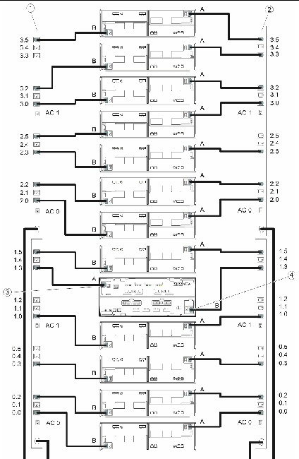
2. Connect each power supply in the tray to a different power source in the rack.
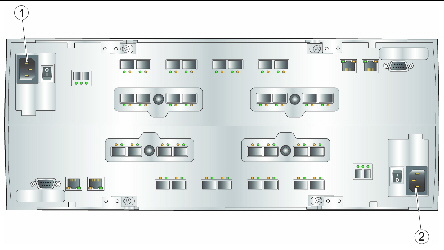
3. Connect the power cables from the rack to the external power source.
FIGURE 2-1 Connecting the Power Cables to the Controller Tray

FIGURE 2-2 Power Connections for 1x13 Array Configuration

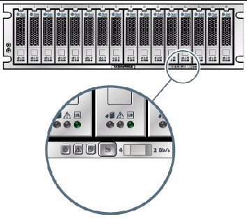
The Tray Link Rate switch (FIGURE 2-3) on each expansion tray is preset to operate at 2 Gbits/second or 4 Gbits/second.
If you added an expansion tray to a factory-assembled array, set the tray link rate as described in Setting the Tray Link Rate.
FIGURE 2-3 Expansion Tray Link Rate Switch

|
Tray Link Rate switch, Left = 4 Gbits/second, Right = 2 Gbits/second |
| Note - The Tray Link Rate switch does not affect the data rate of host ports. |
Use this procedure to turn power on for all trays installed in the rack.
1. Turn on the rack circuit breakers, if applicable.
2. Turn on the two power switches at the back of each expansion tray (see Expansion Tray).
Wait until the tray ID/Diag display on the back indicates the number of the tray ID to be sure that the tray has powered up fully before proceeding to the next step.
3. Turn on the two power switches at the back of the controller tray (see Expansion Tray).
While the tray powers on, the green and amber LEDs at the front and back of the controller tray turn on and off intermittently. Depending on your configuration, it can take several minutes for the tray to power on. Wait at least two minutes until all of the drives are spinning completely before moving to step 4. When the power-on sequence is complete, the controller tray ID indicates 99.
4. Check the status of each tray.
After the power-on sequence is complete, confirm that the green OK/Power LEDs are steady green, both on the tray and on each drive in the tray.
If all tray and drive OK/Power LEDs are steady green and the amber Service Required LEDs are off, the power-on sequence is complete and no faults have been detected.
| Note - The array rarely needs to be powered off. For power-off instructions, see Powering Off the Array. |
Now you are ready to connect the management host and data hosts, as described in Chapter 3.
Copyright © 2009 Sun Microsystems, Inc. All rights reserved.