Making the Flash PROM Write-Enabled
Before you update the OpenBoot firmware contained in the flash PROM, you must set a jumper to the write-enable position (Sun Ultra 1 and Ultra 2 systems) or set the front panel keyswitch to the proper position (Sun Enterprise 450 system and the Sun Ultra 450 workstation).
The Sun Ultra 1 and Ultra 2 systems, which do not have a front panel keyswitch, are equipped with jumpers on their motherboards that allow the flash PROM to be either write-protected or write-enabled. The default position as shipped from the factory is for the flash PROM to be write-protected. In order for the flash PROM to be updated, you must change the jumper to the write-enable position.
Sun Ultra 1 and Ultra 2 Systems: To Change the Jumper to the Write-Enable Position
-
Shut down the system. Type the following:
% su
Type your superuser password
# init 0
System shutdown messages
-
Power off the system unit.
Refer to the installation guide or service manual for your system.
-
Remove the system access cover.
Refer to the installation guide or service manual for your system for this procedure.
-
Use proper grounding procedures such as wearing a wrist strap to avoid electrostatically damaging system components.
Refer to the installation guide or service manual for your system for this procedure.
-
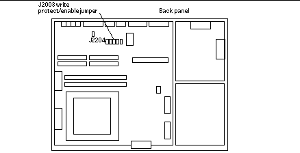
Locate the flash PROM J2003 write-protect/enable jumper on the motherboard in your system:
-
See Figure 4-1 if you have a Sun Ultra 1 Series system.
-
See Figure 4-2 if you have a Sun Ultra 1 Creator Series system.
-
See Figure 4-3 if you have a Sun Ultra 2 system.
You may have to remove a plug-in card if the card is covering the flash PROM jumper. Refer to your service manual for your system to remove the card.
Figure 4-1 Sun Ultra 1 Series Write-Protect/Enable Jumper Location on Motherboard
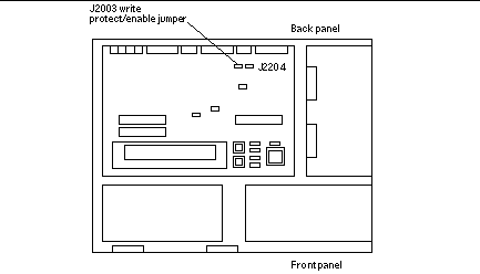
Figure 4-2 Sun Ultra 1 Creator Series Write-Protect/Enable Jumper Location on Motherboard
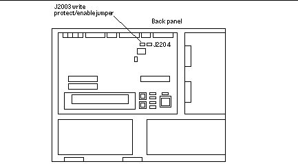
Figure 4-3 Sun Ultra 2 System Write-Protect/Enable Jumper Location on Motherboard
-
-
Set the J2003 write-protect/enable jumper to pins 2 and 3 jumpered (write enabled) using needlenose pliers (see Figure 4-4). Pin 1 is noted by an asterisk (*).
Figure 4-4 Setting the Write-Protect/Enable Jumper to the Write-Enable Position
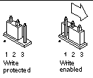 Table 4-4 Jumper Setting
Jumper
Pins 1 + 2 Jumpered
Pins 2 + 3 Jumpered
Default Jumper on Pins
Name
J2003
Write-protect
Write-enable
1 + 2
Write-protect/enable
-
If you removed a plug-in card from the system before changing the jumper, replace the card now.
-
Remove your wrist strap and replace the system access cover.
Refer to the installation guide or service manual for your system for this procedure.
Sun Enterprise 450 System and the Sun Ultra 450 Workstation: Disabling Write Protection
For the Sun Enterprise 450 system and the Sun Ultra 450 workstation you do not have to change jumper pins. Instead, you move the keyswitch to allow the flash PROM to be write-enabled.
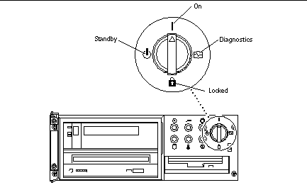
When the switch is set to the Locked position (Figure 4-5), the flash PROM is write-protected. When the switch is set to the On or Diagnostics position, the flash PROM is write-enabled.
To Write Enable the Flash PROM on the Sun Enterprise 450 System and the Sun Ultra 450 Workstation
-
Turn the keyswitch to the On or Diagnostics position (Figure 4-5) before updating the flash PROM.
Note -Disabling write-protection the Sun Enterprise 450 system or the Ultra 450 workstation assumes that the write-protect/enable jumper was set in the default position (enabled). If you previously changed the write-protect/enable jumper to be write protected, perform the steps to make the flash PROM write enabled in "Location of Flash PROM Jumpers in Sun Enterprise 450 System and the Ultra 450 Workstation". You must change the jumper to be write enabled before continuing with the flash PROM update procedure.
Figure 4-5 Sun Enterprise 450 and Sun Ultra 450 Keyswitch Location
- © 2010, Oracle Corporation and/or its affiliates
