| Sun Netra X4250 Server Installation Guide |
| C H A P T E R 3 |
|
Mounting the Server Into a 4-Post Rack |
This chapter provides instructions for installing the server in an open 4-post rack or closed cabinet.
This chapter contains the following sections:
| Note - References to left and right are from your viewpoint as you face either the front or rear of the equipment. |

|
Caution - The server is heavy. Two people are required to lift and mount the server into a rack enclosure when following the procedures in this chapter. |
The server ships with a 19-inch, 4-post hardmount rack kit (see To Install a Server With a Hardmount 19-Inch 4-Post Rack for installation instructions). TABLE 3-1 lists three additional 4-post rackmount kit options that can be ordered from Sun. This chapter provides installation instructions for these rackmount kit options.
|
19-inch, 4-post slide mount kit for 600-800 mm cabinet depths |
To Install a Server With a Sliding Rail Mount in a 19-Inch 4-Post Rack |
|
To Install a Server With a Hardmount in a 600-mm 4-Post Rack |
|
|
19-inch, 4-post slide rail kit for 800-1000 mm cabinet depths with cable management assembly |
Installing a Server With a Sliding Rail Mount in a 19-Inch 4-Post Rack for Use With the Cable Management Assembly |
| Note - If you have more than six DC-powered servers in the same rack, you might exceed Telcordia NEBS EMI limits. |
The hardmount kit for a 19-inch 4-post rack consists of:
| Note - The front-to-back rail spacing must be at least 460 mm (18.11 in.) and not more than 715 mm (28.15 in.) from the outside face of the front rail to the outside face of the back rail. |
FIGURE 3-1 Contents of the Hardmount 19-Inch 4-Post Kit

|
1. Get the hardmount brackets from the rack kit (FIGURE 3-1).
2. Use four of the supplied M5 × 4.5 mm flathead Phillips screws to secure each of the hardmount brackets to the sides of the server (FIGURE 3-2).
FIGURE 3-2 Securing the Hardmount Brackets to the Server

3. Measure the depth of the rack.
4. Get the two rear mount support brackets from the rack kit (FIGURE 3-1).
5. Install the rear mount support brackets at the rear of the server, extending the rear mount support brackets to the measured depth of the rack (FIGURE 3-2).
Use two to three of the supplied M4 × 0.5 × 5 mm panhead Phillips screws for each bracket, depending on the rack depth.
FIGURE 3-3 Attaching the Rear Mount Support Brackets

6. Lift the server to the desired location in the rack.
7. Using two screws per side, secure the front of the hardmount brackets attached to the sides of the server to the front of the rack (FIGURE 3-4).
FIGURE 3-4 Securing the Front of the Server to the Rack

8. Get the two rear mount flanges from the rack kit (FIGURE 3-1).
9. Using two screws for each rear mount support bracket, secure the rear mount support brackets to the rear of the rack (FIGURE 3-5).
FIGURE 3-5 Securing the Rear of the Server to the Rack

The sliding rail mount kit for a 19-inch 4-post rack consists of:
| Note - The front-to-back rail spacing must be at least 392 mm (15.43 in.) and not more than 863.6 mm (34 in.) from the outside face of the front rail to the outside face of the back rail. |
You also need the hardmount brackets from the standard rackmount kit that came with the server (FIGURE 3-6).
FIGURE 3-6 Contents of the Sliding Rail 19-Inch 4-Post Kit

|
1. Get the hardmount brackets and M5 × 4.5 mm flathead Phillips screws from the standard rack kit (FIGURE 3-1).
These hardmount brackets and screws are shipped with the standard server ship kit, not as part of the sliding rail 19-inch 4-post rackmount ship kit.
2. Use four of the supplied M5 × 4.5 mm flathead Phillips screws to secure each of the hardmount brackets to the sides of the server (FIGURE 3-7).
FIGURE 3-7 Securing the Hardmount Bracket to the Server

3. Get the Telco slide assemblies from the rack kit (FIGURE 3-6).
4. Press in the button on each slide and pull the glide completely out of the slide (FIGURE 3-8).
FIGURE 3-8 Dismantling the Slide

5. Using eight of the M4 × 0.5 × 5 mm panhead Phillips screws from the rackmount kit (four for each side), screw each glide to the side of the server chassis (FIGURE 3-9).
FIGURE 3-9 Fixing the Glides to the Server Chassis

6. Get the short brackets and long brackets from the rackmount kit (FIGURE 3-6).
7. Lift each short bracket to the desired position at the front of the rack and attach a short bracket to each of the front rack uprights (FIGURE 3-10).
Use two of the brass M6 collar screws and M6 cage nuts (if required), and one threaded strip, to secure each bracket (FIGURE 3-10).
8. Lift each long bracket to the desired position at the rear of the rack and attach a long bracket to each of the rear rack uprights (FIGURE 3-10).
To secure each bracket, use two of the brass M6 collar screws and M6 cage nuts (if required) and one threaded strip, exactly as you did for the front rack uprights in the previous step.
FIGURE 3-10 Securing the Brackets to the Rack

| Note - If your rack has 10-32 holes, use the 10-32 collar screws and 10-32 threaded strips. |
9. Extend a slide to line up the access holes with the front screw holes.
10. Secure the slide onto the short and long brackets at the front and rear of the rack (FIGURE 3-11).
Use the M5 panhead screws from the inside. Use the M5 nuts, plain washers, and star washers from the outside. Use extension brackets instead of the long brackets if the dimension is greater than 665 mm.
FIGURE 3-11 Securing the Slide to the Brackets

11. Repeat Step 9 and Step 10 for the slide on the other side of the rack.
12. Push the slides completely into the assembly on each side of the rack and release the stop catches.
13. Align the glides attached to the server with the slide assemblies in the rack.
You might find that there is too much or too little room between the two slides mounted in the rack. Consequently the glides attached to the server might not align correctly with the slides in the rack. If either situation occurs, loosen the M6 collar screws and cage nuts on the long and short brackets (Step 7 and Step 8), move the brackets inward or outward to the appropriate points, then tighten them again.
14. Push in the slide buttons and slide the server all the way into the rack enclosure (FIGURE 3-12).
FIGURE 3-12 Sliding the Server Into the Rack

15. Using two screws per side, secure the front of the hardmount brackets that are attached to the sides of the server to the front of the rack (FIGURE 3-13).
The size of the screws varies, depending on your particular rack.
FIGURE 3-13 Securing the Front of the Server to the Rack

The hardmount kit for a 600 mm 4-post rack consists of:
| Note - The front-to-back rail spacing must be at least 392 mm (15.43 in.) and not more than 504 mm (19.84 in.) from the outside face of the front rail to the outside face of the back rail. |
FIGURE 3-14 Contents of the Hardmount 600-mm 4-Post Kit

|
1. Get the adjustable rails from the rack kit (FIGURE 3-14).
2. Loosen the two screws at the middle of each adjustable rail so that you can extend the adjustable rail (FIGURE 3-15).
FIGURE 3-15 Adjustable Rail Screws

3. Lift one of the adjustable rails to the desired location in the rack. Using two screws, secure the front of the rail in the rack (FIGURE 3-16).
The size of the screws varies, depending on your particular rack.
FIGURE 3-16 Securing the Front of the Adjustable Rails to the Rack

4. At the rear of the rack, use two screws to secure the rear of the adjustable rails to the rack (FIGURE 3-17).
The size of the screws varies, depending on your particular rack.
FIGURE 3-17 Securing the Rear of the Adjustable Rails to the Rack

5. Tighten the two screws at the middle of each adjustable rail (FIGURE 3-15).
6. Repeat Step 3 through Step 5 to mount the other adjustable rail into the rack.
7. Get the rear flanges from the rack kit (FIGURE 3-14).
8. Using one M5 × 7 SEM screw for each rear flange, loosely install the rear flange onto the rear of each of the adjustable rails (FIGURE 3-18).
Do not completely secure the rear flanges to the adjustable rails. You will use these flanges to set the rack depth for the server in a later step.
FIGURE 3-18 Installing the Rear Flange Onto the Adjustable Rail

9. Get the side rails from the rack kit (FIGURE 3-14).
10. Using eight of the M5 × 7 SEM screws (four for each side rail), secure the side rails to the sides of the server (FIGURE 3-19).
The side rails can accommodate rack rail setbacks (the distance from the front of the rack to the rack rail) of 50 mm, 75 mm, or 100 mm, depending on the type of rack you are installing the server into.
FIGURE 3-19 Securing the Side Rails to the Server

11. Lift the server into the rack and slide the server onto the adjustable rails (FIGURE 3-20).
FIGURE 3-20 Sliding the Server Onto the Adjustable Rails

12. Push the server to the desired depth in the rack, then go to the rear of the server and push the rear flanges flush against the back of the server (FIGURE 3-18).
If the rack is especially shallow, you can flip the rear flanges around so that they rest flush against the rear of the server.
13. Lift the server out of the rack.
14. Set the rear flanges to the desired depth in the rack, then tighten the single M5 × 7 SEM screw on each of the flanges to secure them to the adjustable rails (FIGURE 3-18).
15. Lift the server into the rack and slide it onto the adjustable rails.
16. Push the server backward until it rests flush against the rear flanges, then use one M5 × 7 SEM screw for each rear flange to secure the rear of the server to the rear flanges (FIGURE 3-21).
FIGURE 3-21 Securing the Rear of the Server to the Rear Flanges

17. At the front of the rack, use two screws per side to secure the side rails that are attached to the server to the front of the rack (FIGURE 3-22).
The size of the screws varies, depending on your particular rack.
FIGURE 3-22 Securing the Front of the Server to the Front of the Rack

| Note - Ensure that you have all of the parts in the rackmount kit before you begin the installation of the server. See Shipping Kit Inventory List. |
The rackmount kit contains two slide rail assemblies. A slide rail assembly can be installed on either the right or left side of the rack.
A slide rail assembly consists of two parts, a slide rail and a removable mounting bracket. The slide rail attaches to the rack posts. The mounting bracket attaches to the chassis.
|
1. Pull both mounting brackets completely out of their respective slide rails:
a. Simultaneously press and hold the upper and lower lock buttons of the slide rail lock (FIGURE 3-23).
FIGURE 3-23 Unlocking the Slide Rail Assembly

b. Pull the mounting bracket out until it locks in the extended position.
c. Slide the mounting bracket release button in the direction shown in FIGURE 3-24, then slide the mounting bracket out of the slide rail.
FIGURE 3-24 Location of the Mounting Bracket Release Button

d. Press the metal lever (labeled Push) on the middle section (FIGURE 3-25) of the sliding rail, then push the middle section back into the rack.
FIGURE 3-25 Unlocking the Slide Rail Middle Section

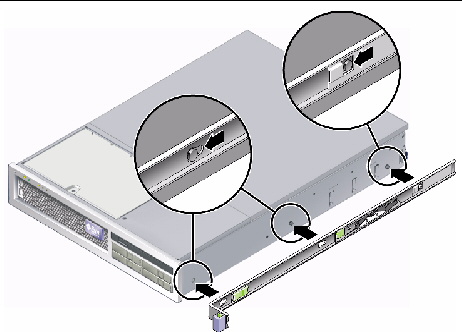
2. Attach a mounting bracket to the right side of the chassis.
a. Position the mounting bracket against the server chassis (FIGURE 3-26) so that the slide rail lock is at the front and the three keyed openings on the mounting bracket are aligned with the three locating pins on the side of the chassis.
FIGURE 3-26 Attaching a Mounting Bracket to the Chassis
b. With the heads of the three locating pins protruding though the three keyed openings in the mounting bracket, pull the mounting bracket toward the front of the chassis until the bracket locks into place with an audible click.
c. Verify that all three locating pins are trapped in the keyed openings and that the rear locating pin has engaged the mounting bracket lock, as shown in the right side of FIGURE 3-26.
3. Attach the second mounting bracket to the left side of the chassis.
4. Determine which rack hole numbers to use when attaching the slide rails to the rack posts.
The server is two rack units tall (2U). The slide rails occupy the lower half of the 2U space.
5. Determine which screws you will use to mount the slide rails.
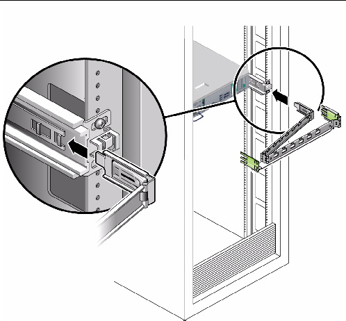
6. Attach a slide rail to the right front rack post.
a. Loosely attach the front of a slide rail to the right front rack post (FIGURE 3-27) using two screws.
FIGURE 3-27 Mounting a Slide Rail

| Note - Do not tighten the screws yet. |
b. Adjust the length of the slide rail by sliding the rear mounting flange to reach the outside edge of the rear rack post.
c. Loosely attach the rear of the slide rail to the rear rack post with two screws.
7. Attach the second slide rail to the left rack posts in a similar manner.
8. Use the slide rail spacing tool to adjust the distance between the slide rails:
a. At the front of the rack, plug the left side of the tool into slots at the end of the left rail (FIGURE 3-28).
FIGURE 3-28 Adjusting the Distance Between the Slide Rails

b. Insert the right side of the tool into the front end of the right rail, while sliding the end of the rail to the right or left as needed to enable the ends of the tool to enter the ends of both rails.
The distance between the rails is now equal to the width of the server with mounting brackets.
c. Tighten the screws to lock the ends of the rails in place.
d. At the rear of the rack, repeat Step a through Step c for the rear ends of the rails.
9. Deploy the antitilt bar, if the chassis or rack is so equipped.
|
|
Caution - The weight of the server on extended slide rails can be enough to overturn a cabinet. |
|
|
Caution - The server weighs approximately 40 lb (18 kg). Two people are required to lift and mount the server into a rack enclosure when using the procedures in this chapter. |
10. Insert the ends of the mounting brackets into the sliding rails (FIGURE 3-29).
FIGURE 3-29 Mounting the Chassis on the Slide Rails

11. Slide the chassis into the rack.
|
|
Caution - Verify that the server is securely mounted in the rack, and that the slide rails are locked to the mounting brackets, before continuing. |
|
The cable management assembly (CMA) clips into the ends of the left and right sliding rail assemblies. No screws are necessary for mounting the CMA.
The right sides of the two CMA arms have hinged extensions. On the manufacturer’s instruction sheet, the smaller extension is called the inner CMA connector. The connector attaches to the right mounting bracket. The larger extension is called the CMA outer connector, and attaches to the right sliding rail.
|
|
Caution - Support the CMA during this installation. Do not permit the assembly to hang by its own weight until it is secured by all three attachment points. |
1. At the rear of the rack, plug the CMA rail extension into the end of the left sliding rail assembly (FIGURE 3-30).
The tab at the front of the rail extension clicks into place.
FIGURE 3-30 Inserting the CMA Rail Extension Into the Rear of the Left Slide Rail

2. Insert the smaller CMA extension into the clip located at the end of the mounting bracket (FIGURE 3-31).
FIGURE 3-31 Mounting the Inner CMA Connector
3. Insert the larger extension into the end of the right rail (FIGURE 3-32).
FIGURE 3-32 Attaching the Outer CMA Connector

4. Insert the hinged plastic connector at the left side of the CMA fully into the CMA rail extension (FIGURE 3-33).
The plastic tab on the CMA rail extension locks the hinged plastic connector in place.
FIGURE 3-33 Mounting the Left Side of the Rail

|
If you are using the CMA on a rack kit with slide rails, follow these steps to ensure that the CMA will not interfere with the ability to move the rack. You must first connect cables to the server.
| Tip - Two people are needed for this procedure, one to move the server in and out of the rack, and one to observe the cables and CMA. |
1. For a cabinet or a free-standing rack, deploy the antitilt bar.
2. Unlock the slide lock buttons (FIGURE 3-34) at the right and left sides of the server chassis, and slowly pull the server out of the rack until the slide rails reach their stops.
FIGURE 3-34 Unlocking the Slide Rail Assembly

3. Inspect the attached cables for any binding or kinks.
4. Verify that the CMA extends fully and does not bind in the slide rails.
5. When the server is fully extended out, release the slide rail lever stops (FIGURE 3-35).
6. Push both levers simultaneously and slide the server back into the rack.
FIGURE 3-35 Unlocking the Slide Rail Lever Stops

7. Simultaneously unlock both slide rail release buttons (FIGURE 3-36) and push the server completely into the rack.
The server should stop after approximately 15 in. (40 cm) of travel.
FIGURE 3-36 Slide Rail Release Button

8. Verify that the cables and the CMA retracted without binding.
9. Adjust the cable hangers and CMA as required.
| Sun Netra X4250 Server Installation Guide | 820-4055-11 |
Copyright © 2010, Oracle and/or its affiliates. All rights reserved.
 To Install a Server With a Hardmount 19-Inch 4-Post Rack