| C H A P T E R 1 |
|
Before You Begin the Installation |
This chapter describes the hardware and software features of the Sun Blade T6340 server module.
The Sun Blade T6340 server module includes the features shown in TABLE 1-1 and TABLE 1-2.
|
Two UltraSPARC® T2 multicore processors with 4MB L2 cache. Can execute up to 128 threads. |
|
|
Up to two hot-pluggable 2.5-inch hard drives. (Filler panels are inserted anywhere hard drives are not installed.) |
|
|
RAID expansion module (hard drive management) with RAID 0, 1 controller. Eight links, x2 SAS (3 Gb/s) or SATA (1.5 Gb/s), supporting up to two internal hard drives and four x2 links to midplane. |
|
|
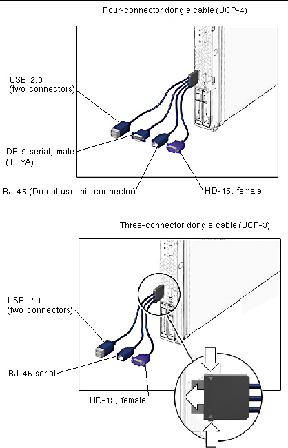
One universal connector port (UCP) in the front panel. A universal cable is included with the chassis and can be purchased separately (FIGURE 1-2). The following connections are supported: |
|
|
SPARC V9 architecture, ECC protected Platform name: SUNW, Sun Blade T6340 Server Module Minimum system firmware 7.0.6 or subsequent compatible release |
|
The Sun Blade T6340 server module is approximately 12.9 x 20.1 x 1.7 inches in a 1U form factor. The server module plugs in to a Sun Blade modular system, or chassis, which provides 12V power to each module, as well as cooling through fans. In addition to the 12V main power, the chassis provides 3.3V AUX power to each module to power the ILOM service processor. This 3.3V AUX power enables the chassis management module (CMM) to query each module slot prior to main power and 12V fan application to validate that there is sufficient power and cooling to support the modules installed in the chassis.
TABLE 1-3 includes the environmental requirements that are specific to the Sun Blade T6340 server module.
FIGURE 1-1 illustrates the front panel, with descriptions of its features.
FIGURE 1-1 Front and Rear Panels
You can order the Sun Blade T6340 server module with one or two hard disk drives assembled to order. You can also order the Solaris Operating System software and other software preinstalled on the root hard drive. For information about preinstalled software, refer to this site:
http://www.sun.com/software/preinstall
Also refer to the Sun Blade T6340 Server Module Product Notes, 820-3901.
Oracle Integrated Lights Out Manager (ILOM) is system management firmware that you can use to monitor, manage, and configure the Sun Blade T6340 server module. The ILOM firmware is preinstalled on the service processor (SP) of the server module. ILOM initializes as soon as you apply power to the system. You can access ILOM through several interfaces, such as web browsers, a command-line interface (CLI), an SNMP interface, and an Intelligent Platform Management Interface (IPMI). ILOM will continue to run regardless of the state of the host operating system.
For information about configuring and using ILOM, refer to these documents:
A service processor (SP) is a circuit board that operates independently of the other hardware in the system. The SP has its own Internet Protocol (IP) address and media access control (MAC) address. The SP can operate when the server module or components are partially operational or powered off. The Sun Blade modular system chassis and every server module in the modular system has its own SP. On some server modules, the service processor is called a system controller.
The Sun Blade modular system, or chassis, has its own service processor, called a chassis management module (CMM). CMM ILOM is a modified version of ILOM firmware that is preinstalled on the CMM.
Before installing the Sun Blade T6340 server module, you should have already installed and configured your Sun Blade modular system, including the CMM ILOM. For more information, refer to the installation guide for your Sun Blade modular system.
ILOM supports two ways to manage a system: using the CMM or using the server module SP directly.
You can establish communication with ILOM through a console connection to the serial management port or through an Ethernet connection to the network management port on the CMM. The type of connection you establish to ILOM determines which types of tasks you can perform. For example, to remotely access the full range of system management functionality in ILOM, you require both an Ethernet connection and an IP assignment to the server module SP and the CMM. For detailed information about configuring and using ILOM, refer to the Sun Integrated Lights out Manager 2.0 User’s Guide, 820-1188 and the Sun Integrated Lights Out Manager 2.0 Supplement for Sun Blade T6340 Server Modules, 820-3904.
You can attach a serial console to the chassis management module (CMM). Refer to the installation guide for your Sun Blade modular system (chassis) for a description of that procedure.
To communicate directly with the Sun Blade T6340 server module, you can connect a serial console to the universal connector port (UCP) on the front panel of the server module by using a dongle cable. See Connecting to the Server Module SP Using a Dongle Cable for more information.
You can order an optional dongle cable with the server module, or you can use the dongle cable that shipped with the modular system chassis. TABLE 1-4 lists the ports to be used for serial connections to the server module using UCP-3 or UCP-4 dongle cables. FIGURE 1-2 shows possible connections on the dongle cable.
You should use the UCP-3 (three connector) dongle cable whenever possible.
 Insert the connector straight into the UCP on the server module (FIGURE 1-2).
FIGURE 1-2 Dongle Cable Connectors

Copyright © 2010, Oracle and/or its affiliates. All rights reserved.