| Skip Navigation Links | |
| Exit Print View | |

|
Sun Blade X6275 M2 Server Module Service Manual |
About This Documentation (PDF and HTML)
Server Module and Components Overview
About the Sun Blade 6000 Modular System Chassis
Powering On and Off the Server Module
Preparation Procedures for Service and Operation
Preparing the Server for Service
Preparing the Server for Operation
Component Removal and Installation Procedures
DIMM Slot Designations and Population Order
DIMM Population Rules and Guidelines for the Sun Blade X6275 M2 Server module
Removing and Installing Flash Modules
Removing and Installing the Energy Storage Modules
Removing and Installing the Service Processor Board
Removing and Installing USB Flash Drives
Removing and Installing a CPU and Heatsink Assembly
How to Replace the Motherboard Assembly
Diagnostic and Maintenance Information and Procedures
Diagnosing Server Module Hardware Faults
BIOS Power-On Self-Test (POST) Codes
Server Module Maintenance Procedures and Information
Note - This component is a customer-replaceable unit (CRU).
Always replace a DIMM with the same Oracle part number as the failed DIMM.
Note - The Sun Blade X6275 M2 Server module is a dual-node server. If necessary, use this procedure for both nodes.
Before You Begin
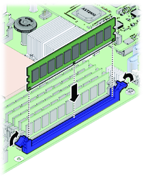
Align the DIMM notch with the key in the connector. This ensures that the DIMM is oriented correctly.

 | Caution - If the DIMM does not easily seat into the connector, verify correct orientation. If the orientation is reversed, damage to the DIMM or DIMM slot might occur. |
Use the ILOM web interface or CLI. Refer to the corresponding ILOM documentation.