5 Servicing FRUs
The following topics describe how to service field-replaceable units (FRUs) for the Oracle Database Appliance. You must power down the system and disconnect the AC power cords from the server before servicing any of these components.
Only Oracle authorized service personnel should service FRU components.
Servicing Oracle Database Appliance X3-2/X4-2/X5-2 FRUs
This section describes how to service server node FRUs for Oracle Database Appliance X3-2, Oracle Database Appliance X4-2, and Oracle Database Appliance X5-2. If you have Oracle Database Appliance (original version), go to Servicing Oracle Database Appliance (Original Version) FRUs.
Only Oracle authorized service personnel should service FRU components.
Note:
Most of the links in the following table take you to instructions outside of the Oracle Database Appliance library to the Sun Server X3-2, Sun Server X4-2, and Oracle Server X5-2 documentation libraries. Use your browser's Back button to return to the Oracle Database Appliance library.| ODA X3-2 | ODA X4-2 | ODA X5-2 |
|---|---|---|
Updating System_Identifier and/or FRU ID Information for a Replacement Motherboard or Disk Backplane
This section is for Oracle field service personnel who replace FRU components, such as the motherboard and disk backplane, that contain special FRU ID information. This FRU ID information includes the System_Identifier and Top Level Identifier (TLI). Maintaining the correct System_Identifier and TLI information in the system is important for the correct operation of the Oracle Database Appliance software and for warranty service.
System_Identifier:
This is an Oracle ILOM setting maintained in the service processor. By logging in to the Oracle ILOM CLI as root, you can reset this value after replacing a server node's motherboard.
FRU ID information:
There are two levels of FRU ID information in Oracle Database Appliance:
-
Oracle Database Appliance TLI product and serial number
-
The component server node product and serial number
The FRU ID information is maintained in the motherboard (MB), disk backplane (DBP0) and power supply (PS0).
An Oracle Database Appliance assembled at the factory has the same appliance TLI product and TLI serial number for each bundled component (server nodes, storage shelves). Components added later, such as the optional storage expansion shelf, might have a different TLI.
Additionally, each server node has its own component-level product number and serial number maintained in the FRU ID.
The appliance TLI and server component numbers can be found on labels attached to the top of each appliance server node near the front and look similar to the following illustration:
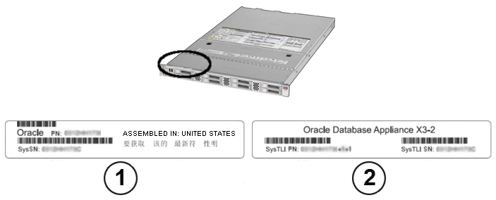
| Callout | Description |
|---|---|
|
1
|
Server serial label
|
|
2
|
Oracle Database Appliance TLI label
|
If the appliance is in a rack where you cannot see the labels, slide a server node partway out on its rails, just far enough to see the information. Refer to Preparing Oracle Database Appliance X3-2/X4-2/X5-2 for Service.
Note:
You only need to extend the server node a couple of inches on its slide rails to see the TLI. You do not need to release any cables, or slide it to the extended maintenance position.Choose a task to perform:
Update System_Identifier Information
Perform the following steps to update the System_Identifier information after replacing a motherboard.
- Log in as root to the service processor of the new motherboard using the Oracle ILOM command line interface.
- Set the system_identifier. For example, if you have a ODA X3-2, enter the following
command:
set /SP system_identifier="Oracle Database Appliance X3-2 TLI serial number"
Where TLI serial number is the Oracle Database Appliance TLI serial number used in common for both nodes of the appliance. Information stored in the system_identifier is used by the appliance software to confirm the server nodes are a matched pair. You can find the TLI serial number on the top of the server (left front). See Updating System_Identifier and/or FRU ID Information for a Replacement Motherboard or Disk Backplane for label location.
- Confirm that the information has been successfully updated by viewing the
system_identifier field. Enter the following command:
show /System
The system information is displayed. For example:
/System Targets: Open_Problems (0) Processors Memory Power Cooling Storage Networking PCI_Devices Firmware BIOS Properties: health = OK health_details = - open_problems_count = 0 type = Rack Mount model = ODA X3-2 part_number = 12341003+2+1 serial_number = 5678FM0001 component_model = SUN FIRE X4170 M3 component_part_number = 7064195 component_serial_number = 1150FML00J system_identifier = Oracle Database Appliance X3-2 5678FM0001 system_fw_version = 3.1.2.10.a - Confirm that the FRU TLI information is also correct for the system, as follows:
-
model: should list the appliance model.
-
part_number: should list the appliance TLI part number.
-
serial_number: should list the appliance TLI serial number.
-
component_model: should list the server node model.
-
component_part_number: should list the server node part number.
-
component_serial_number: should list the server node serial number.
-
- If the information is correct, you are done and can log out. If the information is not correct, proceed to Update Disk Backplane or System FRU TLI Information.
Update Disk Backplane or System FRU TLI Information
Perform the following steps to confirm or update the Oracle Database Appliance TLI and server FRU ID information. This procedure must be performed when replacing the disk backplane board or when TLI or FRU ID information on the motherboard is not automatically updated after replacement.
- Log in using the sunservice account (enabled through Escalation mode) to the service processor
using the Oracle ILOM command line interface.
Upon successful log in, the Service Mode prompt is displayed:
#
- Check the Oracle Database Appliance TLI information, enter the following command:
setsvcid
The setsvcid command obtains backup TLI information stored in the system and displays it for confirmation. For example, on Oracle Database Appliance X3-2 you might see:
Reading fruid:///SYS/DBP0...
Top Level Product Name ['ODA X3-2']:
Top Level PPN ['12341003+2+1']:
Top Level PSN ['5678FM0001']:

Top Level Product Name:    ODA X3-2
Top Level PPN:             12341003+2+1
Top Level PSN:             5678FM0001
Is the above correct? (y|n) [n]:
- If the information displayed is correct, type Y and press Enter. If the
information is not correct, type N and enter the correct information found on
the Oracle Database Appliance TLI label on the top left of the server (see Updating System_Identifier and/or FRU ID Information for a Replacement Motherboard
or Disk Backplane).
The following message is displayed:
Writing fruid:///SYS/DBP0... You will need to reboot the SP for these changes to take full
effect.
- Check the component server FRU information, enter the following command:
setpsnc
The setpsnc command obtains backup component server FRU information stored in the system and displays it for confirmation. For example, on Oracle Database Appliance X3-2 which contains two Sun Server X3-2 (formerly known as Sun Fire X4170 M3) nodes you might see:
Reading fruid:///SYS/DBP0...
PPN ['7064195']:
PSN ['1150FML00J']:
Product Name ['SUN FIRE X4170 M3']:

PPN:             7064195
PSN:             1150FML00J
Product Name:    SUN FIRE X4170 M3
Is the above correct? (y|n) [n]:
- If the information displayed is correct, type Y and press Enter. If the
information is not correct, type N and enter the correct information found on
the server serial label on the top left of the server (see Updating System_Identifier and/or FRU ID Information for a Replacement Motherboard or Disk
Backplane).
The following message is displayed:
Writing fruid:///SYS/DBP0... You will need to reboot the SP for these changes to take full
effect.
- Reboot the SP using the following command:
reboot
Rebooting the SP will automatically log you off.
- After the service processor reboots, log back in to sunservice account using the command line
interface.
Upon successful log in, the Service Mode prompt is displayed:
#
- Confirm that the Oracle Database Appliance TLI information is correct. Enter the following
command:
showsvcid
The system information is displayed. For example:
Top Level Product Manufacturer: Oracle Corporation

Top Level Product Name: ODA X3-2

Top Level PPN: 12341003+2+1

Top Level PSN: 5678FM0001
- Confirm that the component server FRU information is correct. Enter the following
command:
showpsnc
The system information is displayed. For example:
Primary: fruid:///SYS/DBP0
Backup 1: fruid:///SYS/MB
Backup 2: fruid:///SYS/PS0

Element           | Primary           | Backup1           | Backup2
------------------+-------------------+-------------------+-------------------
PPN                 7064195             7064195             7064195
PSN                 1150FML00J          1150FML00J          1150FML00J
Product Name        SUN FIRE X4170 M3   SUN FIRE X4170 M3   SUN FIRE X4170 M3
- If the information is correct, log out. If the information is not correct (does not match the information on the Oracle Database Appliance TLI or server serial labels), repeat the process for information that is missing or incorrect.
Component Fault Management
Typically, when a faulty component is replaced and the server returned to service, the fault state of the component in Oracle ILOM is automatically cleared and the component Service Required indicator will turn off. This is the default behavior for all components that have an embedded FRU serial number in the component firmware.
For replaced components that do not have an embedded FRU serial number, or do not automatically clear their fault state after the component has been repaired and the server is returned to service, you can use Oracle ILOM command line interface to manually clear the fault state. Use the following syntax:
set /path_to_target clear_fault_action=true
Where path_to_target is the path to the component (such as a DIMM) that had the fault.
In addition, the Fault Management shell can also be used. Use of the Fault Management shell is reserved for Oracle Service. For more information on component fault management, see: Using fmadm to Administer Active Sun Hardware Faults in the Oracle Integrated Lights Out Manager Documentation Library.
Servicing Oracle Database Appliance (Original Version) FRUs
This section describes how to service server node FRUs for Oracle Database Appliance (original version). If you have Oracle Database Appliance X3-2, Oracle Database Appliance X4-2, or Oracle Database Appliance X5-2, go to Servicing Oracle Database Appliance X3-2/X4-2/X5-2 FRUs.
Note:
Only Oracle authorized service personnel should service FRU components.Removing and Installing the Air Duct (FRU)
The air duct for the Oracle Database Appliance (original version) must be removed to service the CPUs.
The air duct is a FRU and can only be replaced by an Oracle-qualified service technician.
Caution:
Equipment overheating. Ensure that the air duct is installed correctly before powering on the server.This section includes the following topics:
Remove Air Duct
- Prepare the server node for service.
- Attach an antistatic wrist strap.
See Performing Electrostatic Discharge and Antistatic Prevention Measures.
- Remove the server node from the system.
See Removing Server Nodes From the System Chassis.
Power is removed from the server node when you remove it from the system.
- Remove the server node top cover.
- Attach an antistatic wrist strap.
- Remove the air duct.
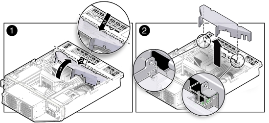
- From the rear of the server node, grasp the middle/rear of the air duct with your right hand
and lift it up to a 45 degree angle [1].
The air duct swings up and away from the rear of the system.
- Grasp the left end of the plastic air duct with your left hand to hold it at a 45 degree angle, and with your right hand press gently down on the middle of the air duct until it bends enough to disengage its left hinge from its socket [2].
- Remove the air duct's right hinge from its socket and set the air duct aside [2].
- From the rear of the server node, grasp the middle/rear of the air duct with your right hand
and lift it up to a 45 degree angle [1].
Install Air Duct
Caution:
Equipment overheating. Ensure that the air duct is installed correctly before powering on the server.- Install the air duct into the chassis.
- From the rear of the server node, insert the air duct's right hinge into the right-side socket [2], and place the left hinge on top of the left-side socket.
- Grasp the left end of the air duct with your left hand to hold it at a 45 degree angle, and, with your right hand, press gently down on the middle of the air duct until it bends enough to insert the left hinge into the left-side socket [2].
- Carefully lower the air duct to its closed position, with particular attention given to the
SAS cables [1].
Ensure that the openings on each side of the air duct fit around the cables and not on top of them.
Caution:
Equipment overheating. Verify that the air duct is fully closed.
- Return the server node to operation.
- Install the server node top cover.
- Install the server node into the system.
- Power on the server node.
See Powering On Oracle Database Appliance (Original Version).
Servicing Processors (CPUs) (FRU)
This section includes information on servicing CPUs in Oracle Database Appliance (original version).
The CPU is a FRU and can only be replaced by an Oracle-qualified service technician.
Caution:
Equipment damage. These procedures require that you handle components that are sensitive to static discharge. This sensitivity can cause the component to fail. To avoid damage, ensure that you follow antistatic practices as described in Performing Electrostatic Discharge and Antistatic Prevention Measures.This section includes the following topics:
Remove Processor (CPU)
- Prepare the server node for service.
- Attach an antistatic wrist strap.
See Performing Electrostatic Discharge and Antistatic Prevention Measures.
- Remove the server node from the system.
Power is removed from the server node when you remove it from the system. See Removing Server Nodes From the System Chassis.
- Remove the server node top cover.
- Remove the air duct.
See Remove Air Duct.
- Attach an antistatic wrist strap.
- Remove the CPU.
- Identify which CPU to remove.
- To identify the location of the faulty CPU, press the Fault Remind button on the motherboard.
Note:
When the Fault Remind button is pressed, the Fault Remind Power Good indicator (LED) lights green to indicate that there is sufficient voltage present in the fault remind circuit to light the fault indicators. If this indicator fails to light when you press the Fault Remind button, the capacitor powering the fault remind circuit has lost its charge. This can happen if the Fault Remind button is pressed for a long time with fault indicators lit or if the server node has been out of the chassis for more then 15 minutes. - The fault LED for the faulty CPU lights.
The fault LED is located next to the CPU.
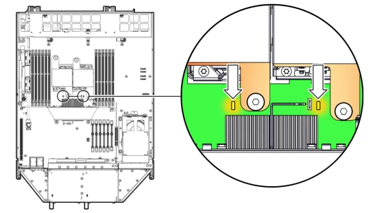
- If CPU fault LED is off: CPU is operating properly.
- If CPU fault LED is on (amber): CPU is faulty and should be replaced.
Viewing the server node from the front, CPU0 (P0) is on the right side of the server node.
- Using a Phillips screwdriver, turn one captive screw on the heatsink counterclockwise two full turns, then turn the other screw two full turns, and keep alternating between the two screws until they are removed [2].
- Twist the heatsink slightly to break the grease seal, then lift it off and place it upside down on a flat surface to prevent the thermal grease from contaminating other components.
- Using the wipes supplied with the replacement CPU, carefully clean the thermal grease from
both the bottom of the heatsink and the top of the CPU.
Caution:
Equipment damage. When cleaning the top of the CPU, be careful not to get the thermal grease on the CPU socket and associated components.Caution:
Equipment damage. Failure to clean the heatsink and CPU prior to removing the CPU could result in the accidental contamination of the CPU socket or other components. Also, be careful not to get the grease on your fingers as this could result in contamination of components. - Disengage the CPU release lever by pushing down and moving it to the side away from the CPU, and then rotating the lever upward [3].
- Raise the pressure frame on the CPU to the open position [3].
- Use your index finger to carefully lift up the edge of the CPU or protective cap that is
farthest from the socket alignment slots [4], then firmly grasp both sides of the CPU or protective
cap with your thumb and index finger on your other hand [4], and carefully lift the CPU or
protective cap up and out of the socket [5].
Caution:
Equipment overheating.Whenever you remove a heatsink, you should replace it or install a CPU filler before you return the server to operation; otherwise, the system might overheat due to improper airflow.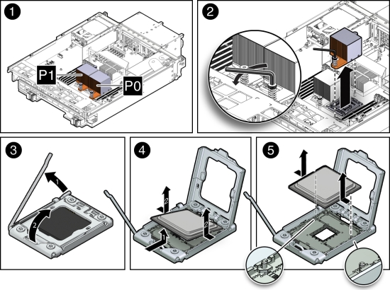
Install Processor (CPU)
- Attach an antistatic wrist strap.
See Performing Electrostatic Discharge and Antistatic Prevention Measures.
- Unpack the replacement CPU.
The CPU replacement kit includes a new CPU, wipes, and a tube of thermal grease.
- Install the CPU.
- Grasp the sides of the CPU firmly with your thumb and index finger, tilt it at a 45 degree
angle, orient it with the socket alignment tabs [2], carefully lower the end of the CPU with the
alignment tabs into the socket [3], support the raised end of the CPU with the index finger on your
other hand, and lower the CPU into the socket [3].
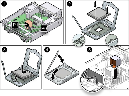
- Lower the pressure frame to the closed position [4].
Ensure that the pressure frame sits flat around the periphery of the CPU.
- Engage the release lever by rotating it downward and slipping it under the catch [4].
- Ensure that there is no debris on the top of the CPU die.
- Use the syringe (supplied with the new or replacement CPU) to apply approximately 0.1 ml of thermal grease to the center of the top of the CPU. Do not distribute the grease.
- Orient the heatsink so that the DIMM SIDE label on the top of the heatsink is facing the
memory modules (DIMMs) and the two captive Phillips screws align with the mounting studs.
Each heatsink is labeled to indicate which side of the heatsink faces the memory modules (DIMMs) when the heatsink is properly oriented.
- Tighten the two Phillips screws alternately two full turns at a time until the screws are fully seated [5].
- Grasp the sides of the CPU firmly with your thumb and index finger, tilt it at a 45 degree
angle, orient it with the socket alignment tabs [2], carefully lower the end of the CPU with the
alignment tabs into the socket [3], support the raised end of the CPU with the index finger on your
other hand, and lower the CPU into the socket [3].
- Return the server node to operation.
- Install the air duct.
See Install Air Duct.
- Install the server node top cover.
- Install the server node into the system.
- Power on the server node.
See Powering On Oracle Database Appliance (Original Version).
- Install the air duct.
- Clear the CPU faults.
- Log in to the server node as root using the Oracle ILOM CLI.
- To view server node faults, type the following command to list all known faults on the
system:
-> show /SP/faultmgmt
Oracle ILOM lists all known faults, for example:
SP/faultmgmt
Targets:
0 (/SYS/MB/P0)
Properties:
Commands:
cd
show
- To clear the fault, type the following command:
-> set /SYS/MB/Pn clear_fault_action=true
For example, to clear a fault on P0:
-> set /SYS/MB/P0 clear_fault_action=true
Are you sure you want to clear /SYS/MB/P0 (y/n)? y
Set 'clear_fault_action' to 'true'
Servicing the Boot Disk Backplane (FRU)
The Oracle Database Appliance (original version) boot disk backplane (BDB) serves as an interface between the motherboard and the rear-mounted disk drives.
The boot disk backplane is a FRU and can only be replaced by an Oracle-qualified service technician.
Caution:
Equipment damage. These procedures require that you handle components that are sensitive to static discharge. This sensitivity can cause the component to fail. To avoid damage, ensure that you follow antistatic practices as described in Performing Electrostatic Discharge and Antistatic Prevention Measures.This section includes:
Remove Boot Disk Backplane
- Prepare the server node for service.
- Attach an antistatic wrist strap.
See Performing Electrostatic Discharge and Antistatic Prevention Measures.
- Remove the server node from the system.
Power is removed from the server node when you remove it from the system. See Removing Server Nodes From the System Chassis.
- Remove the server node top cover.
- Attach an antistatic wrist strap.
- Unseat the boot disk drives.
See Remove a Boot Drive.
- Remove the boot disk backplane.
- Disconnect the power and data cables [1].
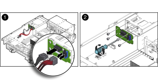
- Remove the four Phillips screws that secure the boot disk backplane to the rear-mounted disk drives assembly and remove the backplane [2].
- Disconnect the power and data cables [1].
- Place the boot disk backplane on an antistatic mat.
Install Boot Disk Backplane
- Install the boot disk backplane.
- Position the boot disk backplane on the rear-mounted disk drives assembly and install and tighten the four Phillips screws to secure the backplane [2].
- Reconnect the power cable and the data cables [1].
- Return the server node to operation.
- Re-seat the boot disk drives.
See Install a Boot Drive.
- Install the server node top cover.
- Install the server node into the system.
- Power on the server node.
See Powering On Oracle Database Appliance (Original Version).
- Re-seat the boot disk drives.
Servicing the Power Distribution Board (FRU)
The Oracle Database Appliance (original version) power distribution board (PDB) distributes power from the power supplies to all system components.
The power distribution board is a FRU and can only be replaced by an Oracle-qualified service technician.
Caution:
Equipment damage. Follow antistatic precautions as described in Performing Electrostatic Discharge and Antistatic Prevention Measures. Do not touch the components along their connector edges.Caution:
Equipment damage. Remove all power from the system before removing or installing the power distribution board. Power down both server nodes (also called system controllers) and disconnect the power cords from the system before performing these procedures. For instructions, see Shutting Down a Server Node and Powering Off the System.This section includes:
Remove Power Distribution Board
- Prepare the system for service.
- Power off the system.
See Shutting Down a Server Node and Powering Off the System.
- Disconnect the power cords from the system.
- If the system is installed in a rack, remove it.
For information on racking the system chassis, see the Oracle Database Appliance Owner's Guide.
- Remove both power supplies from the system.
- Attach an antistatic wrist strap.
See Performing Electrostatic Discharge and Antistatic Prevention Measures.
- Power off the system.
- Remove both server nodes from the system.
- Remove the middle section of the system top cover.
- Remove the power distribution board.
- Disconnect the ribbon cable connector on the power distribution
board [1].
The ribbon cable is located between the power distribution board and the chassis side wall. It connects the power distribution board to the disk midplane.
- Remove the two Phillips screws that secure the power distribution
board to the chassis [2].
You access the screws through two holes in the side of the chassis.
- Carefully remove the chassis interlock switch connector from the
power distribution board [3].
To gain access to the chassis interlock switch connector, grasp the power distribution board with both hands, slide it to the rear of the system chassis to unplug it from the disk midplane module, and lift it up until you can grasp and remove the connector.
- Lift the power distribution board out of the system chassis [4]
and place it on the antistatic mat.
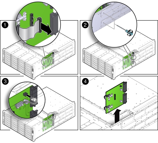
- Disconnect the ribbon cable connector on the power distribution
board [1].
Install Power Distribution Board
- Install the power distribution board into the system chassis.
- Lower the power distribution board partially into the system [1].
- Reconnect the chassis interlock switch cable [2].
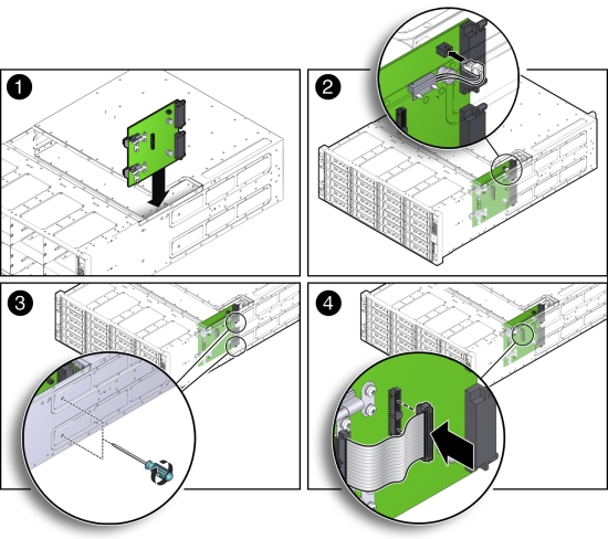
- Align the power distribution board with the two power connectors on the disk midplane module and slide the power distribution board forward until the connectors seat.
- To secure the power distribution board to the system, use the holes in the system side wall to access and tighten the two Phillips screws [3].
- Reconnect the power distribution board ribbon cable [4].
- Return the system to operation.
- Install both server nodes into the system.
- Install the middle section of the top cover.
Install and tighten the Phillips screws that secure the middle section of the top cover to the system chassis.
- Install both power supplies into the system.
- If the system was installed in a rack, reinstall it into the rack.
See the Oracle Database Appliance Owner's Guide for instructions.
- Reconnect the power cords to the system and power on the system.
See Powering On Oracle Database Appliance (Original Version).
Servicing the Disk Midplane Module (FRU)
The Oracle Database Appliance (original version) disk midplane interconnects the front disk drives to the server nodes, the front indicator modules, and the power distribution board (PDB).
The disk midplane board is a FRU and can only be replaced by an Oracle-qualified service technician.
Caution:
Equipment damage. Follow antistatic precautions as described in Performing Electrostatic Discharge and Antistatic Prevention Measures. Do not touch the components along their connector edges.Caution:
Equipment damage. Remove all power from the system before removing or installing the power distribution board. Power down both server nodes (also called system controllers) and disconnect the power cords from the system before performing these procedures. For instructions, see Shutting Down a Server Node and Powering Off the System.This section includes:
Remove Disk Midplane Module
- Prepare the system for service.
- Power off the system.
See Shutting Down a Server Node and Powering Off the System.
- Disconnect the power cords from the system.
- If the system is installed in a rack, remove it.
See the Oracle Database Appliance Owner's Guide for information on racking the system chassis.
- Remove both power supplies from the system.
- Attach an antistatic wrist strap.
See Performing Electrostatic Discharge and Antistatic Prevention Measures.
- Power off the system.
- Remove all of the front storage drives.
- Remove both server nodes from the system.
- Remove the middle section of the system top cover.
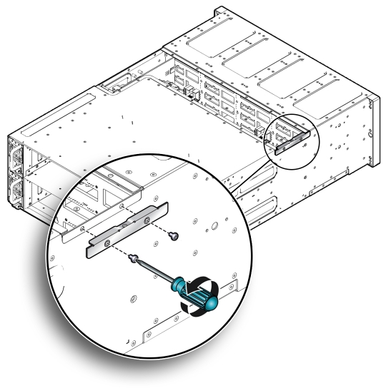
- Loosen the two captive Phillips screws that secure the side-wall
cover to the chassis and remove the cover.
The side-wall cover is positioned under the middle section of the system top cover. Before you can remove the side-wall cover, you must remove the middle section of the system top cover.
- Remove the power distribution board.
- Remove the disk midplane module.
- Before disconnecting the two front indicator module (FIM) cable
connectors from the disk midplane module, label them [1].
The lower connector on the disk midplane is for SN0 and the upper connector is for SN1.
- Disconnect the two FIM cable connectors from the disk midplane
module [1].
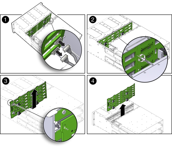
- Remove the Phillips screw that secures the disk midplane module to the disk drive cage [2].
- To remove the disk midplane module from the system chassis, lift
the board up about 0.25 inches (6.35 mm) to clear the standoffs that hold
it in place [3].
To remove the board, you might need to move the bottom of the board away from the disk drive cage to disengage the standoff located at the top left corner of the board. Then, you should be able to lift the board up and out of the system.
There are four columns of standoffs, four in the left-most column and three in each of the remaining columns.
- Lift the disk midplane module up and out of the system [4].
- Place the board on an antistatic mat.
- Before disconnecting the two front indicator module (FIM) cable
connectors from the disk midplane module, label them [1].
Install Disk Midplane Module
- Install the disk midplane module.
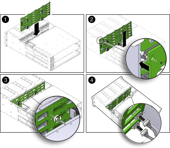
- Move the front indicator module (FIM) cable connectors toward the rear of the system so that the disk midplane module is not installed over them.
- Lower the disk midplane module in the system chassis [1].
- Position the disk midplane module against the disk drive cage, tilting the top slightly forward so that it fits over the top-most standoff on the left side and then position board so that it fits over the remaining 12 standoffs, then push downward on the board to engage the standoffs [2].
- To secure the disk midplane module to the disk drive cage, install the Phillips screw [3].
- Reconnect the two FIM cable connectors to the receptacles on the
disk midplane module [4].
Ensure that the FIM connectors are properly connected. The lower connector on the disk midplane is for SN0 and the upper connector is for SN1.
- Install the power distribution board into the system.
- Position the side-wall cover into the chassis and tighten the two captive Phillips screws to secure the side-wall cover to the chassis.
- Install the middle section of the system's top cover.
Install and tighten the Phillips screws that secure the middle section of the top cover to the system chassis.
- Reinstall all of the front storage drives.
- Reinstall both server nodes into the system.
- Return the system to operation.
- Install both power supplies into the system.
- If the system was installed in a rack, reinstall it into the rack.
See the Oracle Database Appliance Owner's Guide for instructions.
- Reconnect the power cords to the system and power on the system.
See Powering On Oracle Database Appliance (Original Version).
Servicing the Disk Midplane Module HDD Cable (FRU)
The Oracle Database Appliance (original version) HDD cable connects the power distribution board to the disk midplane module.
The disk midplane module HDD cable is a FRU and can only be replaced by an Oracle-qualified service technician.
Caution:
Equipment damage. Remove all power from the system before removing or installing the disk midplane module HDD cable. Power down both server nodes (also called system controllers) and disconnect the power cords from the system before performing these procedures. For instructions, see Shutting Down a Server Node and Powering Off the System.The following topics are covered in this section:
Remove Disk Midplane Module HDD Cable
- Prepare the system for service.
- Power off the system.
See Shutting Down a Server Node and Powering Off the System.
- Disconnect the power cords from the system.
- If the system is installed in a rack, remove it.
See the Oracle Database Appliance Owner's Guide for instructions.
- Attach an antistatic wrist strap.
See Performing Electrostatic Discharge and Antistatic Prevention Measures.
- Power off the system.
- Remove the middle section of the system top cover.
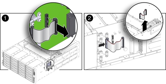
- Disconnect the HDD ribbon cable connector located on the power distribution board [1]).
- Disconnect the HDD ribbon cable connector located on the disk
midplane module [2].
Install Disk Midplane Module HDD Cable
- Reconnect the HDD ribbon cable connector located on the disk midplane module [2]).
- Reconnect the HDD ribbon cable connector located on the power distribution board [1].
- Return the system to operation.
- Install the middle section of the system top cover.
Install and tighten the Phillips screws that secure the middle section of the top cover to the system chassis.
- If the system was installed in a rack, reinstall it into the rack.
See the Oracle Database Appliance Owner's Guide for instructions.
- Reconnect the power cords to the system and power on the system.
See Powering On Oracle Database Appliance (Original Version).
- Install the middle section of the system top cover.
Servicing the Front Indicator Panels (FRU)
The Oracle Database Appliance (original version) front indicator panels contain the LEDs and indicators on the front of the system. Each server node has its own front indicator panel, which sits behind the ears on the system chassis.
The front indicator panels are FRUs and can only be replaced by an Oracle-qualified service technician.
Caution:
Equipment damage. Remove all power from the system before removing or installing the disk midplane module HDD cable. Power down both server nodes (also called system controllers) and disconnect the power cords from the system before performing these procedures. For instructions, see Shutting Down a Server Node and Powering Off the System.The following topics are covered in this section:
Remove Front Indicator Panel
- Prepare the system for service.
- Power off the system (both server nodes).
See Shutting Down a Server Node and Powering Off the System.
- Disconnect the power cords from the system.
- If the system is installed in a rack, remove it.
See the Oracle Database Appliance Owner's Guide for information on racking the system chassis.
- Attach an antistatic wrist strap.
See Performing Electrostatic Discharge and Antistatic Prevention Measures.
- Power off the system (both server nodes).
- Remove the adjacent disk drives [1].
Be sure to mark them so that you can return them to the correct drive bays later.
- Unscrew the three Phillips screws from the back of the ear bezel [2].
- Remove four more Phillips screws from the inside of the drive bays [3].
- Remove the ear bezel [4].
The ear bezel and indicator panels remain connected to the ribbon cables.
- Disconnect the ribbon cables from the indicator panel you wish to change [5].
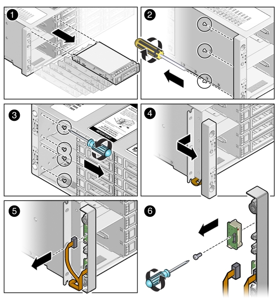
- Remove the screw that holds the indicator panel to the ear bezel [6].
Make sure you remove the correct indicator panel. There are two indicator panels on the ear bezel.
Install Front Indicator Panel
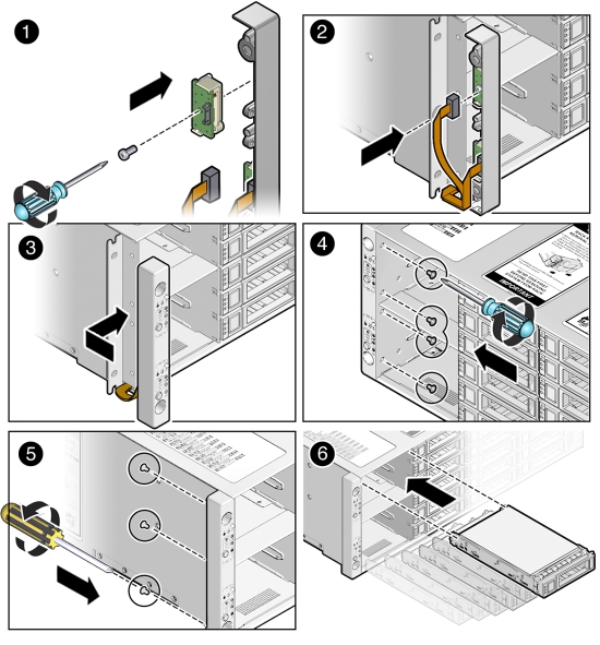
- Use the Phillips screw to attach the new indicator panel to the ear bezel [1].
- Connect the ribbon cable to the indicator panel [2].
- Place the ear bezel on the chassis [3].
- Fasten the four Phillips screws inside the drive bays [4].
- Fasten the three Phillips screws on the back of the ear bezel [5].
- Replace the disk drives in the drive bays [6].
Use the marks to ensure that you return each drive to its original bay.
- Return the system to operation.
- Reinstall the system into the rack.
See the Oracle Database Appliance Owner's Guide for instructions.
- Reconnect the power cords to the system and power on the system.
See Powering On Oracle Database Appliance (Original Version).
- Reinstall the system into the rack.
Servicing Server Node Cables
This section includes information on servicing cables in Oracle Database Appliance (original version).
The internal server node cables are FRUs and can only be replaced by an Oracle-qualified service technician.
Caution:
Equipment damage. These procedures require that you handle components that are sensitive to static discharge. This sensitivity can cause the component to fail. To avoid damage, ensure that you follow antistatic practices as described in Performing Electrostatic Discharge and Antistatic Prevention Measures.The following topics are covered in this section:
Servicing the Fan Power Cables (FRU)
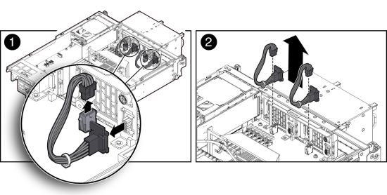
Each Oracle Database Appliance (original version) server node has two fans and each fan has a separate power cable.
Remove Fan Power Cables
- Prepare the server node for service.
- Attach an antistatic wrist strap.
See Performing Electrostatic Discharge and Antistatic Prevention Measures.
- Remove the server node from the system.
Power is removed from the server node when you remove it from the system. See Removing Server Nodes From the System Chassis.
- Remove the server node top cover.
- Attach an antistatic wrist strap.
- Disconnect the fan power cables and remove them from the server node.
Install Fan Power Cables
- Reconnect the fan power cables.
- Return the server node to operation.
- Install the server node top cover.
- Install the server node into the system.
- Power on the server node.
See Powering On Oracle Database Appliance (Original Version).
Servicing the PCIe Card Cables (FRU)
The Oracle Database Appliance (original version) PCIe card cables are used to connect the internal PCIe card, the primary HBA and a riser-mounted PCIe card, and the secondary HBA to the motherboard. See the following sections for instructions.
The PCIe card cables are FRUs and can only be replaced by an Oracle-qualified service technician.
Remove PCIe Card Cables From Primary HBA PCIe Card
- Prepare the server node for service.
- Attach an antistatic wrist strap.
See Performing Electrostatic Discharge and Antistatic Prevention Measures.
- Remove the server node from the system.
Power is removed from the server node when you remove it from the system. See Removing Server Nodes From the System Chassis.
- Remove the server node top cover.
- Attach an antistatic wrist strap.
- Disconnect the primary HBA PCIe card cables and remove them from the server node.
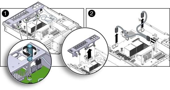
- Loosen the three green, captive Phillips screws that secure the server node's front cover and remove the cover [1].
- Disconnect the two cables from the primary HBA PCIe card and remove the cables [2].
To remove each cable connector, push the connector inward, press down on the connector to release it, and pull the connector out.
Install PCIe Card Cables for Primary HBA PCIe Card
- Reconnect the PCIe card cables.
- Reconnect the two PCIe card cables to the primary HBA PCIe card and the connectors on the
motherboard [2].
Notice that there are two sets of connectors on the motherboard. Be sure to connect the cables to the connector on the right in each set (looking at the connectors from the rear of the server node).
- Position the server node's front cover onto the server node and tighten the three green, captive Phillips screws that secure the server node's front cover to the motherboard [1].
- Reconnect the two PCIe card cables to the primary HBA PCIe card and the connectors on the
motherboard [2].
- Return the server node to operation.
- Install the server node top cover.
- Install the server node into the system.
- Power on the server node.
See Powering On Oracle Database Appliance (Original Version).
Remove PCIe Card Cables From Secondary HBA PCIe Card
- Prepare the server node for service.
- Attach an antistatic wrist strap.
See Performing Electrostatic Discharge and Antistatic Prevention Measures.
- Remove the server node from the system.
Power is removed from the server node when you remove it from the system. See Removing Server Nodes From the System Chassis.
- Remove the server node top cover.
- Attach an antistatic wrist strap.
- Disconnect the PCIe card cables and remove them from the server node.
The Secondary HBA PCIe Card sits in the top slot on the PCIe riser (PCIe slot 2)
- Loosen the three green, captive Phillips screws that secure the server node's front cover and remove the cover [1].
- Disconnect the two secondary HBA PCIe card cables and remove the cables [2].
To remove each cable connector, push the connector inward, press down on the connector to release it, and pull the connector out.
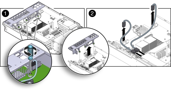
Install PCIe Card Cables for Secondary HBA PCIe Card
- Reconnect the PCIe card cables.
- Reconnect the two PCIe card cables between to the secondary PCIe card and the connectors on
the motherboard [2].
The Secondary HBA PCIe Card sits in the top slot on the PCIe riser (PCIe slot 2)
Notice that there are two sets of connectors on the motherboard. Be sure to connect the cables to connector on the left in each set (looking at the connectors from the rear of the server node).
- Position the server node's front cover onto the server node and tighten the three green, captive Phillips screws that secure the server node's front cover to the motherboard [1].
- Reconnect the two PCIe card cables between to the secondary PCIe card and the connectors on
the motherboard [2].
- Return the server node to operation.
- Install the server node top cover.
- Install the server node into the system.
- Power on the server node.
See Powering On Oracle Database Appliance (Original Version).
Servicing the SAS Expander Cable (FRU)
The Oracle Database Appliance (original version) SAS expander cable runs from a connector on the front of the motherboard to a connector near the rear of the motherboard. See the following sections for instructions.
The SAS expander cable is a FRU and can only be replaced by an Oracle-qualified service technician.
The following topics are covered in this section:
Remove SAS Expander Cable
- Prepare the server node for service.
- Attach an antistatic wrist strap.
See Performing Electrostatic Discharge and Antistatic Prevention Measures.
- Remove the server node from the system.
Power is removed from the server node when you remove it from the system. See Removing Server Nodes From the System Chassis.
- Remove the server node top cover.
- Remove the PCIe riser.
See Shutting Down a Server Node and Powering Off the System.
- Attach an antistatic wrist strap.
- Disconnect the SAS expander cable and remove it from the server node.
- Loosen the three green, captive Phillips screws that secure the server node's front cover and remove the cover [1].
- Disconnect both cable connectors from the motherboard and remove the cable [2].
Push the connector inward, press down on the connector to release it, and pull the connector out.
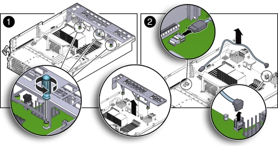
Install SAS Expander Cable
- Reconnect the SAS expander cable.
- Reconnect the SAS expander cable connectors to the motherboard [2].
- Position the server node's front cover onto the server node and tighten the three green, captive Phillips screws that secure the server node's front cover to the motherboard [1].
- Return the server node to operation.
- Install the PCIe riser.
- Install the server node top cover.
- Install the server node into the system.
- Power on the server node.
See Powering On Oracle Database Appliance (Original Version).
Servicing the Boot Disk Backplane Cables (FRU)
The Oracle Database Appliance (original version) boot disk backplane cables connect the boot disk backplane to the motherboard.
The boot disk backplane cables are FRUs and can only be replaced by an Oracle-qualified service technician.
The following topics are covered in this section:
Remove Boot Disk Backplane Cables
- Prepare the server node for service.
- Attach an antistatic wrist strap.
See Performing Electrostatic Discharge and Antistatic Prevention Measures.
- Remove the server node from the system.
Power is removed from the server node when you remove it from the system. See Removing Server Nodes From the System Chassis.
- Remove the server node top cover.
- Attach an antistatic wrist strap.
- Disconnect the power cable and hard disk drive (HDD) cables and remove them from the server
node.
- Disconnect the power cable and HDD cables from the motherboard [1].
- Disconnect the power cable and HDD cables from the boot disk backplane [2].
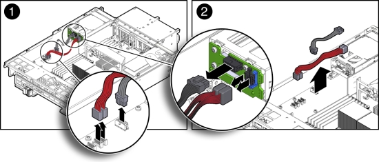
Install Boot Disk Backplane Cables
- Reconnect the power cable and hard disk drive (HDD) cables.
- Reconnect the power cable and HDD cables to the boot disk backplane [2].
- Reconnect the power cable and HDD cables to the motherboard [1].
- Return the server node to operation.
- Install the server node top cover.
- Install the server node into the system.
- Power on the server node.
See Powering On Oracle Database Appliance (Original Version).
Servicing the Motherboard Assembly (FRU)
Each Oracle Database Appliance (original version) server node has a motherboard assembly. The service strategy for the motherboard is to remove the replaceable components from the server node and then return the server node with the motherboard in place to Oracle for repair or replacement.
The motherboard assembly is a FRU and can only be replaced by an Oracle-qualified service technician.
Caution:
Equipment damage. These procedures require that you handle components that are sensitive to static discharge. This sensitivity can cause the component to fail. To avoid damage, ensure that you follow antistatic practices as described in Performing Electrostatic Discharge and Antistatic Prevention Measures.The following figure shows the components that must be removed from the server node.
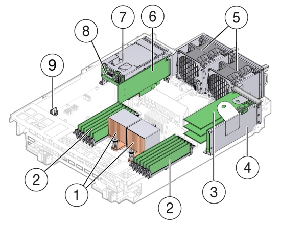
| Callout | Description | Callout | Description |
|---|---|---|---|
|
1
|
CPUs and Heatsinks
|
6
|
Internally Mounted PCIe Card
|
|
2
|
Memory modules (DIMMs)
|
7
|
Boot Disk Drives (2)
|
|
3
|
PCIe Cards mounted on the PCIe Riser
|
8
|
Boot Disk Drive Backplane
|
|
4
|
PCIe Riser
|
9
|
Battery
|
|
5
|
Fan Modules (2)
|
The following topics are covered in this section:
Remove Replaceable Components From Motherboard Assembly
- Prepare the server node for service.
- Attach an antistatic wrist strap.
See Performing Electrostatic Discharge and Antistatic Prevention Measures.
- Remove the server node from the system.
Power is removed from the server node when you remove it from the system. See Removing Server Nodes From the System Chassis.
- Remove the server node top cover.
- Attach an antistatic wrist strap.
- With the exception the SAS expander cable, disconnect and remove all internal cables from the
server node.
Note:
To identify the SAS expander cable, see Install SAS Expander Cable.The cables for the fans, the primary and secondary HBA PCIe cards, and the boot disk backplane must be removed.
-
Fan power cables
See Remove Remove Fan Power Cables.
-
Primary HBA PCIe card data cables
-
Secondary HBA PCIe card data cables
See Remove PCIe Card Cables From Secondary HBA PCIe Card.
Caution:
Equipment damage. The HBA data cables are delicate. Ensure that they are removed and safely out of the way when servicing the motherboard. -
Boot disk board cables.
-
- Remove the following components from the server node.
-
Fan modules
-
Boot disk drives
-
Boot disk drive backplane
-
Memory modules (DIMMS)
-
PCIe riser and attached PCIe cards
-
CPUs
-
Internal PCIe card
-
Battery
-
Install Replaceable Components in Motherboard Assembly
- Attach an antistatic wrist strap.
See Performing Electrostatic Discharge and Antistatic Prevention Measures.
- Install the following components into the server node.
-
Fan modules
See Install a Fan Module.
-
Boot disk drives
See Install a Boot Drive.
-
Memory modules (DIMMS)
See Install DIMMs.
-
PCIe riser and attached PCIe cards
-
CPUs
-
Internal PCIe card
-
- Reconnect and install the following cables.
-
Fan module power cables.
-
Internal PCIe card data cables.
See Servicing the PCIe Card Cables (FRU).
Caution:
Equipment damage. The disk drive data cables are delicate. Handle them carefully. -
Boot disk backplane cables.
-
- Return the server node to operation.
- Install the server node top cover.
- Install the server node into the system.
- Reconnect all external data cables from the PCIe card(s) that are installed in the PCIe riser.
- Power on the server node.
See Powering On Oracle Database Appliance (Original Version).