7 Networks
The following information is included:
7.1 Introduction to Network Management
Oracle Enterprise Manager Ops Center manages network resources, from the physical to the virtual. Fabrics provide the physical infrastructure and network domains provide the logical infrastructure. Networks are created from the resources of a network domain.
Oracle Enterprise Manager Ops Center supports Ethernet and InfiniBand network protocols. While the Ethernet interconnect is the established and common interconnect, InfiniBand is popular in high-performance computing environments because it maximizes the speed of transactions using the short, multiple connections found in clusters and data centers.
-
For an Ethernet network, both tagged and untagged VLANs are supported.
-
For an InfiniBand network, partitions are supported.
Note:
If you use an InfiniBand switch in an Ethernet network, the ports on the switch have Ethernet names.7.2 Roles Required for Network Management
Figure 7-0 lists the tasks and the role required to complete the task. Contact your administrator if you do not have the necessary role or privilege to complete a task. See the Oracle Enterprise Manager Ops Center Administration Guide for information about the different roles and the permissions they grant.
Table 7-1 Network Tasks and Roles
| Task | Role |
|---|---|
|
Edit Network Domain |
Network Admin |
|
Edit Network Attributes |
Network Admin |
|
Edit Network Services |
Network Admin |
|
Aggregate Links |
Network Admin |
|
Create IPMP Groups |
Network Admin |
|
Attach Network to Server Pool |
Cloud Admin |
|
Create Network |
Network Admin |
|
Create Private Network |
Network Admin |
|
Create Network Domain |
Network Admin |
|
Define Network |
Network Admin |
|
Delete Network Domain |
Network Admin |
|
Delete Network |
Network Admin |
|
Define Ethernet Fabric |
Network Admin |
|
Add Fabric |
Network Admin |
|
Remove Fabric |
Network Admin |
|
Assign Network |
Network Admin |
|
Connect Guests |
Network Admin |
|
Discover and Manage the Switches |
Network Admin |
|
Configure Network for Server Deployment |
Server Deployment Admin |
7.3 Actions for a Network and Network Domain
After a network is discovered or created, you can perform the following actions, depending on the requirements.
-
Edit Network Attributes
-
Edit Network Services
-
Aggregate Links
-
Create IPMP Groups
-
Attach Network to Server Pool
-
Define Network
-
Delete Network
-
Assign Network
-
Connect Guests
-
Discover and manage the switches
7.4 Location of Network Information in the User Interface
Figure 7-0 shows where to find information.
Table 7-2 Location of Network Information in the BUI
| Object | Location |
|---|---|
|
Fabric |
Expand Networks in the Assets pane. Then select Fabrics. |
|
Physical Fabric |
Expand Networks in the Assets pane. Then select Fabrics and select Network Switches. |
|
Network |
To see all networks, regardless of type, expand Networks in the Assets pane. Then select Network Domains. |
|
Services of a Network |
Network Services tab: time server, WINS, DNS, and NIS. To modify these services, edit the network services. You cannot change the network's IP address or name. |
|
Network Domain |
Expand Networks in the Assets tree. The Default Network Domain is the first item. |
|
Physical switch |
Expand Assets and expand Network Switches. To see each port, click the Connectivity tab. |
7.5 Fabrics
The fabric is the physical network infrastructure, such as switches, ports, host bus adapters, that provides network resources, through a network domain, to virtual assets.
When you use Oracle Enterprise Manager Ops Center to discover a physical switch or the host of switch, all the switching fabrics that the switch supports are also discovered. One physical fabric supports many fabrics, also called data links. The physical fabric is the collection of all switch ports, links, and physical interfaces or endpoints.
Each port on an Ethernet switch can support 128 fabrics through a VLAN ID. Each partition on an InfiniBand switch can support 32000 partition keys.The members of a partition are identified by partition keys or "P-keys," which act like Ethernet's VLAN tags. For example, if a server has two P-Keys, it participates in two different partitions.
Fabrics provide network resources in a way that depends on their type. Table 7-4 shows the types of fabrics.
Table 7-3 Fabrics and the Network Domain
| na | What Is Managed | Capability | Limits |
|---|---|---|---|
|
The switch is a managed asset. |
You can create a dynamic private network for each VLAN ID or partition key. |
This type of fabric can be achieved on only the Sun Ethernet 10GbE Fabric switch or the Sun Datacenter InfiniBand switch and gateway. |
|
|
The host of the switch is a managed asset. The VLAN IDs or partition keys are available. |
After you enable the VLAN IDs or partition keys on the switch ports connected to the hos, you can create a dynamic private network for each VLAN ID or partition key. |
This type of fabric is the most common type. To create a host-managed fabric from an existing Ethernet fabric, use the Define Ethernet Fabric action. |
|
|
The switch is discovered or declared during the discovery of another asset but is not managed. |
You can create static private networks. |
This type of fabric cannot support dynamic private networks because the VLAN IDs or partition keys are not available. |
7.6 Network Domains
A network domain is a container for fabrics, managed networks, and private networks. The network domain and handles the relationship between the physical fabrics and the virtual assets, such as virtualization hosts or server pools. The fabrics provide data links and IP subnets to the network domain, which in turn, provides networks to the the virtualization hosts and server pools.
Within the network domain, networks that have been discovered or specified are available for assignment. These are called public networks because their IP address space has been specified for their exclusive use. Another type of network is private, that is, the network is created using an IP address space that the network domain allocates to it.
A fabric can contribute to more than one network domain. When a network domain has more than one fabric, you designate one of the fabrics as the anchor fabric, which is the fabric from which new networks are created.
Public networks can be members of more than one network domain because their IP addresses are specific and dedicated. Private networks exist only within a specific network domain. This means a different network domain could construct a private network with the same IP address without a conflict.
In Oracle Enterprise Manager Ops Center, networks become part of a network domain in the following ways:
-
An asset that has a network is discovered.
-
A user creates a network.
-
A network is created when it is required. This is a dynamic network.
Oracle Enterprise Manager Ops Center operates on more than one layer of the Open Systems Interconnection model, using the network domain. Table 7-4 shows what the network domain manages in the physical to logical stack.
Table 7-4 Elements of a Network Domain
| Layer | Asset | What Is Managed | Capability |
|---|---|---|---|
|
Layer 3 Network: IP address |
For Ethernet: fabric networks For InfiniBand: non-fabric networks |
IP subnet and mask IP address range VLAN or Partition Services Routing |
The network provides connectivity. |
|
Layer 2 Data links |
For a tagged Ethernet: VLAN For an untagged Ethernet: portID For InfiniBand: partition |
VLAN IDs Partition keys (P-key) |
A virtual host uses the virtual NIC and a virtual switch in a VLAN or partition. |
|
Layer 1 Physical: switches, ports, host bus adapters |
Fabrics |
Varies, by type of fabric. See Table 7-3 |
Varies by type of fabric. See Table 7-3 |
7.6.1 Default Network Domain
The Oracle Enterprise Manager Ops Center software always has a Default Network Domain and all networks are members of it. If you have upgraded your product software from the previous release, the existing managed networks are now in the Default Network Domain. A new network becomes a member of the default network domain. If you direct the new network to a user-defined network domain, the network is also a member of that network domain.
7.6.2 User-Defined Network Domains
Like the default network domain, a user-defined network domain provides network resources to a server pool or virtualization host. You create a network domain to support the use of virtualization hosts, server pools, or a virtual datacenter. For example, a virtual datacenter uses server, storage, and network resources in a dynamic way, allocating and releasing resources whenever necessary. The network domain provides the network resources to the virtual datacenter.
Note:
The Create Network Domain action is disabled for Exalogic systems because these systems use the Default Network Domain for all resources.When you create a network domain, you set a limit on the number of networks that can be created in the network domain. Increase the number of networks when accounts in a virtual datacenter are not able to create vnets.
A new user-defined network domain includes the address space specified as private by the RFC 1918 specification. These addresses cannot be routed to the Internet and provide a way for organizations to create intranets. If you organization uses a portion of this private address space, reserve these IP addresses when you create a network domain so that the network domain does not use them.
7.6.3 Editing Attributes of a User-Defined Network Domain
You can change the name and description of the network domain and you can change the number of dynamic networks that are in use simultaneously.
To Edit Attributes of a Network Domain
-
Expand Libraries in the Navigation pane.
-
Expand Networks in the Navigation pane.
-
Select the network domain.
-
Click Edit Attributes in the Actions pane.
The Details tab is displayed in the center pane. The Name Description, and Number of Networks fields are now editable.
-
Edit the name or description or increase the number of networks.
-
Click Save.
7.7 Networks
In Oracle Enterprise Manager Ops Center, networks are the discovered and managed IP subnets. Oracle Enterprise Manager Ops Center manages network resources for its virtualization hosts.
Note:
These networks are part of Oracle Enterprise Manager Ops Center's virtualization services. For a description of the networks that support the product, see Oracle Enterprise Manager Ops Center's Networks.Networks are associated with server pools, which contain virtualization hosts, or standalone virtualization hosts. When you assign a network to a server pool, the network is accessible from each virtualization hosts in the pool and every guest of each virtualization host.
You can use networks to do the following:
-
Manage individual virtualization hosts
-
Connect virtualization hosts to the Proxy Controller
-
Allow guests to communicate with each other or with the Internet
-
Connect remote JMX with the public API
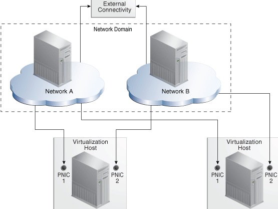
A network depends on the physical network interface card (PNIC) that is available to the host. You can create one network for each physical network interface card. If one host has two PNICs, it is a good practice to create two networks: a management network and a data network. Then place all virtual hosts on the data network, keeping them separate from the management network. The management network is dedicated to giving access to internal resources of the data center.
Figure 7-1 shows how two virtualization hosts participate in two networks. The actual network connection is made to the PNICs in the virtualization host. Network A is connected to PNIC 1 of both hosts and Network B is connected to PNIC 2 of the hosts.
7.7.1 Requirements for a Network
A network requires a physical network interface or a link aggregation and the following specifications:
-
IP address and netmask or CIDR format
-
If you use static IP addressing, the IP address of the management interface
If you use dynamic IP addressing, the range of allowed IP addresses and the gateway address
7.7.2 Public Networks and Private Networks
Networks are introduced into Oracle Enterprise Manager Ops Center in the followings ways:
-
By discovering the fabric that supports the networks. All the attributes are discovered but, other than the name and description, they cannot be changed.
-
By defining the specific attributes of the network from its fabric. This is the result of the Define Network action. In previous versions, this action was called Manage Network.
-
By creating a network from the network domain. This is the result of the Create Network action when you assign the specific VLAN IDs or partition keys and the Create Private Network action when you allow Oracle Enterprise Manager Ops Center to fulfill the requirements from the network domain. For the procedures for creating these types of networks, see the see the How To library at
http://docs.oracle.com/cd/E27363_01/nav/howto.htm
You can use public network for most purposes. If you are creating networks for the use of virtual datacenters, create a private network to ensure that the virtual datacenter has exclusive use of the IP address space that it gets from the network domain.
7.7.3 Networks for Server Pools
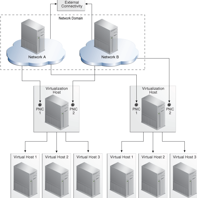
A server pool obtains its networks from a network domain. When you create a server pool, you associate a network domain with the server pool and you specify the physical network interfaces in the fabric that the virtualization hosts in the server pool will use. All virtualization hosts in the server pool are associated with the same set of networks. When you add a virtualization host to a server pool, the virtualization host has access to all the networks defined for the pool and can be an active member of the pool. Figure 7-2 is an example of network connections to two virtualization hosts in a server pool. This server pool has two virtualization hosts and two network associations.
Figure 7-2 Network Connections for a Server Pool
Description of "Figure 7-2 Network Connections for a Server Pool"
All the virtual hosts of a virtualization host have the same network access. This allows you to migrate a virtual host from one virtualization host to another one within the pool.
7.7.4 Networks for Oracle Solaris Zones
You specify the networks that support a global zone. The network attached to a global zone also supports its non-global zones. You can attach one or more networks to a global zone using the Attach Networks action.
Although the fabric that supports the network does not change, you can specify the way the network works differently for each type of zone. A network that is assigned as shared on a global zone can be assigned as exclusive on another global zone.
-
In Shared IP mode, more than one zone uses the network interface. You define the network interface when you assign the global zone to the network.
-
In Exclusive IP mode, the network interface is dedicated to the zone. An exclusive network must be declared for the global zone when you assign network to the global zone. Then you configure the IP configuration for the non-global zone.
For a complete description, see Managing Global Zone Networks in Chapter 14.
7.7.5 Networks for Oracle VM Servers
The Oracle VM Server Control Domain's network support is specified when the Oracle VM Server software is installed to provide networking facilities for the logical domains. For each network connection, a virtual switch is created.
For a complete description of networks for Oracle VM Server for SPARC, see Attaching Networks in Chapter 15.
For a complete description of networks for Oracle VM Server for x86, see Manage Networks in Chapter 16.
7.7.6 Networks for Virtual Datacenters
Each virtual datacenter uses server, storage, and network resources in a dynamic way, allocating and releasing resources when necessary. The virtual datacenter inherits its network resources from the network domain that supports the server pool. These networks form the public external networks for the virtual datacenter. These networks can then be assigned to the accounts in the virtual datacenter. When the user of an account creates a private vNet, either a dynamic private network is created or the static private network is made available for use in that account.
The public networks assigned to a virtual datacenter are shared among the accounts in a virtual datacenter. You can attach virtual servers from different accounts to the same network. When you create a virtual server, you specify the number of networks to which it can be associated.
Although the network domain provides the private network, the virtual datacenter creates virtual networks from each IP address. The size of the private network, that is the maximum number of members that you specify, is the maximum number of IP addresses or virtual networks and therefore, the maximum number of virtual servers that can connect to the private network. Virtual networks are displayed in the vDC Management section of the Navigation pane as shown in Figure 18-1.
For a complete description of networks for virtual datacenters, see Creating vNets and Network Setup in Chapter 18.
7.7.7 Bandwidth Management
A data link is a physical NIC, an aggregated link, or a virtual NIC. When a new data link is created, the operating system sets the default bandwidth flow. You cannot remove this flow. The flow is removed only when the physical link is removed.
In Oracle Solaris 11 operating system environments, you can manage the bandwidth flow of a data link, prioritizing the network traffic on the link and setting the maximum bandwidth limit.
7.7.7.1 Managing the Bandwidth Flows for a Data Link
-
Expand Assets in the Navigation pane.
-
Select an Oracle Solaris 11 operating system.
-
Click the Networks tab in the center pane.
-
Click the Bandwidth Management subtab in the center pane.
-
To modify a flow, click the Modify icon. To create a new link, click the Add icon, then specify a name for the flow and the physical network interface.
The name of flow must meet the following requirements:
-
The first character must be alphabetic.
-
All characters must be alphanumeric: a-z, A-Z, 0-9, underscore ('_'), period ('.') , or hyphen ('-').
-
Maximum number of characters is 127.
-
-
Set the new bandwidth properties, as described in Properties of Bandwidth Flow.
7.7.7.2 Properties of Bandwidth Flow
-
Priority – Set the priority of the network traffic on the link as high, medium or low.
-
Bandwidth Limit – Enable the bandwidth limit to allocate guaranteed bandwidth to the specified link. Enter the maximum value for bandwidth limit in Kbps, Mbps, or Gbps.
-
Set attributes for the data flow to identify its network traffic:
-
Local and Remote IP – The source and destination IP address.
-
Transport – The Internet Protocol used such as TCP, UDP. SCTP, ICMP.
-
Ports – The source and destination ports for TCP, UDP, and SCTP.
-
DS Field – The type of service field in the IP packets' header.
-
7.7.8 IP Multipathing Groups
Using IP Multipathing (IPMP), two or more physical network interface cards (NIC) form a group that use one IP address. If one NIC fails, the other NIC in the group maintains network access.
A network interface can be a physical network interface card (NIC) or, for an Oracle Solaris OS asset, it can be an IPMP group or link aggregation. You can implement both methods on the same network because they work at different layers of the network stack.
For information about how IPMP groups work, see the Oracle Solaris 11 documentation at http://docs.oracle.com/cd/E23824_01/html/821-1458/gfkcy.html and the Oracle Solaris 10 documentation at http://docs.oracle.com/cd/E26505_01/html/E27061/mpoverview.html.
Note:
IPMP groups are supported only for IPv4 protocol.IPMP provides increased reliability, availability, and network performance for systems with multiple physical interfaces because IPMP detects a physical interface failure and migrates network access to another member transparently.
Using IPMP, you can configure two or more physical interfaces into an IPMP group. If an interface in the group fails or is removed for maintenance, IPMP migrates the failed interface's IP addresses to another member of the group. The failover feature of IPMP preserves connectivity and prevents disruption of any existing connections.
The association between an IPMP group and a network must be unique; an IPMP group can be associated with only one network and a network can be associated with only one IPMP group or individual NICs.
In an IPMP group, you define whether each interface is a failover or a standby one. The actions of each type differ if the current network interface fails:
-
Network access changes from the failed interface to the failover interface in the IPMP group and uses the failover interface data address. You must provide the data address for an interface that is defined as failover.
-
Network access changes from the failed interface to the standby interface in the IPMP group but does not change its data address. The data address of the failed interface migrates to the standby interface.
Link-based failure detection in an IPMP group is always enabled if your interface supports this type of failure detection. You can also set up probe-based failure detection by providing a test address for each interface in the group.
You can create a single IPMP group while provisioning an operating system. If you create IPMP groups manually, Oracle Enterprise Manager Ops Center identifies and displays the groups on the UI. See Creating IPMP Groups for information and procedures for creating IPMP groups.
7.7.9 Creating IPMP Groups
Note:
For Oracle Solaris 11 OS, you cannot create IPMP groups. Instead, you can aggregate the links.From the Network tabs, you have the option to create and manage the IPMP groups in the selected Oracle Solaris OS. Figure 7-3 shows the options that are available to create and manage IPMP groups.
To create an IPMP group, you must the define the following parameters for the group:
-
The active and the standby interfaces of the group. By default, an interface added to an IPMP group is active. You can configure as many standby interfaces as you want for the group.
-
The link-based failure detection is enabled by default. You must select whether you want to enable Probe-Based failure detection and if so, you must provide the test address to track the interface status.
-
You must assign the data addresses for the physical interfaces in the IPMP group. Data traffic flow use the data addresses that are hosted on the IPMP interface and flow through the active interfaces of that group.
-
Click the Network tab in the center pane.
-
Click the IPMP Groups subtab in the pane.
Existing IPMP groups in the OS are listed.
-
Click the Create IPMP Group icon to open the Create IPMP Group wizard.
-
Enter the following details for the IPMP group:
-
Provide a name for the IPMP group.
-
Select a network from the list of available network interfaces.
-
The Link-Based failure detection is always enabled by default. Select whether you want to enable Probe-Based failure detection.
-
Select the interfaces in the IPMP group.
Figure 7-4 shows the Specify IPMP Group Wizard step.
Click Next to specify the NIC settings.
-
-
When you have enabled probe-based failure detection, enter the test address for the NICs in the group.
-
Select the interfaces that are in standby mode.
You must have at least one active interface in the group. Click Next.
-
Enter the data address for the active interfaces of the group and select whether the interface has a failover and click Next.
-
Review the information and click Finish to create the IPMP group.
7.7.10 Link Aggregation or Bond
A network interface can be a physical network interface card (NIC) or, for an Oracle Solaris OS asset, it can be an IPMP group or link aggregation. You can implement both methods on the same network because they work at different layers of the network stack.
In an aggregated link, two or more NICs form a group and all members of the link aggregation provide network access at the same time. In addition to the high availability and load balancing that an IPMP group provides, an aggregated link can also provide increased throughput if the network ports are also aggregated.
When interfaces have been aggregated, they are treated as a single network interface. Oracle Enterprise Manager Ops Center includes any link aggregations in the list of available NICs as if the link aggregation were an individual interface. To assign a network with a link aggregation to an Oracle VM Server or global zone, select the link aggregation from the NIC list. You can view the link aggregation details on the Oracle VM Server's or global zone's Network tab as described in Creating Link Aggregation.
Link aggregation is a standard defined in IEEE802.3ad. An aggregated link consists of several interfaces on a system configured as a single, logical unit. Link aggregation increases the speed and high availability of a connection between a server and a switch. The most common protocol used to manage link aggregation is LACP (Linked Aggregation Control Protocol). For information about how link aggregation works, see the Oracle Solaris 11 documentation at http://docs.oracle.com/cd/E23824_01/html/821-1458/fpjvl.html and the Oracle Solaris 10 documentation at http://docs.oracle.com/cd/E26505_01/html/E27061/fpjvl.html.
In Oracle Solaris 10 and by default in Oracle Solaris 11, the type of link aggregation you create is a trunk aggregation, which has these requirements:
-
All the members of the aggregated link are connected to the same switch.
-
The members of the aggregated link are of the same type. For example, NICs with the
e1000ginterface cannot be mixed with NICs that use thebgeinterface. -
The required driver is
GLDv3.
Oracle Solaris 11 supports an alternative to trunk aggregation called Datalink Mulipathing Aggregations (DLMP). This type of aggregation overcomes the limitations of trunk aggregation for network virtualization because DLMP aggregation works with more than one switch and provides the benefits of the link layer of the network stack to the aggregation.
In a trunk aggregation, every port is associated with every datalink in the link aggregation. In a DLMP aggregation, every port is associated with every datalink in the link aggregation and every port is associated with the primary network interface and any of its VNICs that are configured to use the link aggregation.
Note:
In the current release, Oracle Enterprise Manager Ops Center can display the details of both trunk and DLMP aggregation and displays them for selection when attaching a network. However, it is not possible to create a DLMP link aggregation.For a link aggregation created in Oracle Solaris 11 OS, the MTU size for one of the members of the aggregation must be at least 9216 bytes to allow Oracle VM Servers and logical domains to use VLAN tagged networks. To change the MTU size, see the instructions in Maximum Transmission Unit (MTU).
7.7.11 Creating Link Aggregation
To create a link aggregation for the Oracle Solaris OS, specify the following:
-
Load balancing policy
-
LACP mode and timer
-
MAC address policy and if required, the MAC address
-
Click the Link Aggregation subtab.
-
Click the Create Link Aggregation icon to open the wizard.
-
Enter the name of the link aggregation. By default, the name starts with
aggrAppend a number to make the name unique. -
Select the NICS for the link aggregation and then click Next
-
Specify the following information:
-
Policy for load balancing
-
LACP mode and timer.
-
MAC address policy and MAC address if required.
Click Next to view the summary.
-
-
Review the information and click Finish to create the link aggregation.
7.8 Properties of a Network
The characteristics of a network are displayed in its Network Details tab.
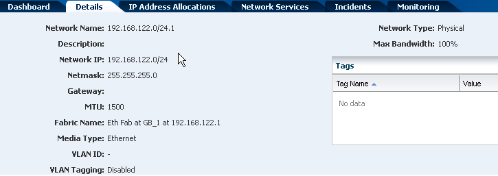
The network IP address and its network type cannot be changed. Use the Edit Network Attributes action to change the network name and description, default gateway, MTU size, and to change the static IP routes. To change the MTU size, see the instructions in Maximum Transmission Unit (MTU).
Use the Edit Managed IP Ranges action to change the range of IP addresses that are available from the selected network. You specify the range with the starting IP address and the ending IP address. You have the option to exclude a specific IP address from the range. When you attach the network to a virtualization host, server pool, or virtual data center, this IP address is not available. You cannot exclude an IP address that is in use, which can be difficult to determine. For example, in a virtual data center, an account is assigned a range of IP addresses for its exclusive use. While the account exists, the IP addresses are in use, regardless of whether there is network activity.
7.8.1 IPv4 and IPv6 Protocols
Some environments have a mix of IPv4 and IPv6. Oracle Enterprise Manager Ops Center is "IPv6-aware." If an asset has an IPv6 network interface, Oracle Enterprise Manager Ops Center can read it and displays its information, but it cannot provision an IPv6 network or use IPv6 networks to discover, monitor, or provision assets.
7.8.2 Routing Mode
A virtual host uses the network assigned to it according to the host's routing mode. You specify a virtual host's routing mode during its initial configuration if you do not accept the default mode, Automatic Routing. Oracle Enterprise Manager Ops Center supports the following routing modes:
-
Automatic Routing – This is the default routing mode. Applying the static routes depends on the following conditions:
-
If your site defined a default gateway or static route or retrieved one from the DHCP server, this route is used and dynamic routing is disabled.
-
If no default gateway or static route is available, dynamic routing is enabled.
-
-
Dynamic Routing Off – The virtual host uses the default gateway and any static routes configured for the network. The default gateway is retrieved from the DHCP server.
-
Dynamic Routing On – The virtual host uses routes provided by the dynamic routing service. The default gateway and any static routes configured for the network are ignored.
7.8.3 Static Route for the Network
Static routes specify the route for external access. Although you define a default gateway for a network, it might not reach a particular subnet. In this case, you must also provide a static route for the subnet.
When you create a network, you can specify the static route. To add static routes after the network has been created, use the following procedure.
To Add a Static Route for the Network
-
Click Managed Networks in the Navigation pane.
-
Select a network from the list of networks.
-
Click Edit Network Attributes in the Actions pane.
-
Click the Add icon in the Static Routes table. A row is added to the table.
-
Enter the values for destination IP, netmask, and gateway.
-
Click Finish.
You can delete a static route and change the order of the routes using the icons in the Static Routes table.
7.8.4 Address Allocation Method
When you define a new network, you specify how its IP address is assigned:
-
Static IP: You enter a specific IP address.
-
Automatic: An available IP address is assigned to the network.
-
Do not allocate IP: No IP address is assigned at this time.
7.8.5 Maximum Transmission Unit (MTU)
The default size for the network's Maximum Transmission Unit (MTU) is 1500 bytes. If your network interface card is one of the following types, you can change the size of the MTU to a size between 576 and 9216 bytes. However, to assign the network to a logical domain, the minimum MTU size is 1500 bytes.
-
e1000g -
ce -
nxge -
nge -
bge -
xge -
hme -
ixgbe -
hxge -
ipge -
igb
When you specify a size greater than 1500 bytes, Oracle Enterprise Manager Ops Center modifies the network interface card's MTU size. For other types of network interface cards, the MTU is changed when the card's driver firmware is updated to support the new MTU size. However, to change the MTU value for an IPMP group, you must edit the MTU value manually.
Note:
When you provision an operating system, the MTU size resets to the default value. You must change the MTU again after you provision the system.7.8.6 VLAN and VLAN Tags
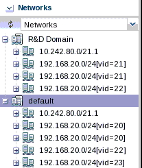
For fabrics based on Ethernet protocol, the ability to use VLAN tags is an attribute of each network. Use the Edit Network Attributes action to add or change the VLAN capability. Use the Define Network action to specify a network as tagged, untagged, or both.
When one CIDR supports both tagged and untagged networks, you can distinguish them by the default User Friendly Name (UFN), as shown in Figure 7-6. Oracle Enterprise Manager Ops Center appends the VLAN ID or tag to the UFN. For an untagged network with no VLAN ID, the string [UNTAG] is appended.
7.9 Network Utilization
Oracle Enterprise Manager Ops Center collects information every five minutes on every managed asset and displays the last hour of data on the asset. To see utilization data for a network over longer periods of time, up to six months, create a Network Utilization chart, which includes operating system, operating system for a virtual machine, virtual host, and server pool. You can also create a network utilization chart for an OS group or host group.
7.10 Network Connectivity
Connectivity is the network interface of the system. You can view information about a hardware asset's Network Interface Card (NIC) on the Connectivity tab of the asset's dashboard, including name, connection status, MAC address, and the corresponding IP address.
For switch hardware, the Connectivity tab shows information about each port.
For an Oracle Solaris OS, the Connectivity tab includes IPMP groups and aggregated links.
-
The IPMP Groups subtab shows the group's name, its assigned network, and the type of failure detection, either link-based, probe-based, or both. For each IPMP group, the details include the state of the connection for each NIC, whether it is in standby mode or failover mode, and the IP address the NIC supports.
-
The Link Aggregation subtab shows the aggregation's name, its MAC address, and its attributes. For each aggregated link, the subtab shows the state of the connection for each NIC, whether it is in standby mode or failover mode, and the IP address the NIC supports.
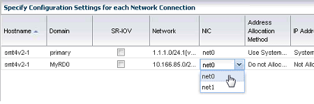
When you attach or assign networks or when you create virtual hosts, Figure 7-7 shows an example of a step in the wizard where you configure the network connection.
7.11 Network Hardware
Oracle Enterprise Manager Ops Center can manage Sun Ethernet 10GbE Fabric switches and Sun Datacenter InfiniBand switches. These switches reside in the system or blade system and provide the switch fabric.
The InfiniBand Gateway switch can expose the ports of a server that resides on an InfiniBand partition to an Ethernet network. To create an Ethernet on InfiniBand (EoIB) interface on the switch, you associate the switch's external port (eport) with the InfiniBand partition where the server resides, creating a virtual NIC (vNIC). The server's ports are displayed on the Switch Connectivity tab in the center pane.
For more information about these switches, see Switch Details or see Related Resources for Networks for links to the switch documentation.
7.11.1 Network Interface Card (NIC)
The Network Interface Card (NIC) is the physical connection between a network switch and a network. When you create a network or attach an asset to a network, you select the NIC. You can create one network for each physical network interface card. To see the NICs for a server, select the server and then click the Connectivity tab. The Server Processor Connectivity table lists all of the NICs.
7.11.2 Network Switches
Oracle Enterprise Manager Ops Center can manage Sun Ethernet 10GbE Fabric switches and Sun Datacenter InfiniBand switches. These switches reside in the system or blade system and provide the switch fabric.
For the Ethernet switches, both tagged and untagged VLANs are supported.
If you use an InfiniBand switch in an Ethernet network, the ports on the switch have Ethernet names.
For more information about these switches, see the product documentation:
-
For the Sun Ethernet 10GbE Fabric switch, see
http://docs.oracle.com/cd/E19934-01/index.html -
For Sun Datacenter InfiniBand switch, see
http://docs.oracle.com/cd/E19654-01/index.html
7.12 Network Profiles
Oracle Enterprise Manager Ops Center provides default profiles for the following operations:
-
Monitor Network hardware – Reports Cisco switch's connection to assets on the Switch Connectivity tab.
-
Discover a switch – Use a discovery profile with Cisco iOS credentials.
7.13 Oracle Enterprise Manager Ops Center's Networks
This section describes the requirements for the networks that Oracle Enterprise Manager Ops Center uses. This section does not discuss the networks that support virtual hosts and server pools.
You can implement Oracle Enterprise Manager Ops Center's network connections using any combination of VLANs and switches. However, each network, whether management, provisioning, or data, must be assigned to separate VLANs.
7.13.1 Network Switch Configuration
Use these guidelines to configure a network switch for a system running the Oracle Enterprise Manager Ops Center software.
-
Use an Virtual LAN (VLAN)-capable switch.
-
Discover and manage the switch.
-
Create a separate VLAN for Oracle Enterprise Manager Ops Center management and provisioning networks.
For Ethernet connectivity:
-
The management network must be a 10/100 connection.
-
The provisioning and data networks must be at least a 10/100/1000 (1 GB) connection.
7.13.2 Separate Management, Provisioning, and Data Networks
-
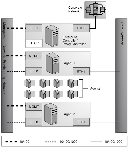
Separate networks, as shown in Figure 7-8, provide the highest security and the lowest number of points of failure.
-
Additional NICs are needed to support this configuration.
Figure 7-8 Separate Management, Provisioning, and Data Networks
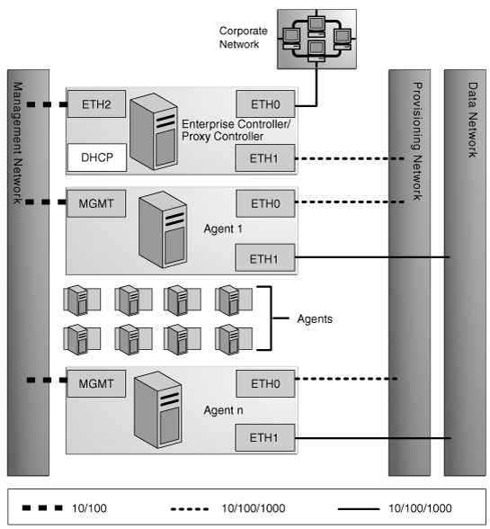
Description of "Figure 7-8 Separate Management, Provisioning, and Data Networks"
A configuration with separate management, provisioning, and data networks has these requirements:
-
Enterprise Controller/Proxy Controller
-
ETH0 connects the Enterprise Controller/Proxy Controller to the corporate network for external access. Configure the ETH0 IP address, netmask, and gateway to meet corporate connectivity requirements.
-
ETH1 connects the Enterprise Controller/Proxy Controller to the provisioning network and must be on the same network as the ETH0 connections of the Agent Controllers. Only the Enterprise Controller/Proxy Controller and the Agent Controllers must reside on the provisioning network. ETH1 must be a 1 Gb NIC interface.
-
ETH2 connects the Enterprise Controller/Proxy Controller to the management network and must be on the same network as the management port connections of the Agent Controllers. Configure the ETH2 IP address, netmask, and gateway to enable connectivity to the Agent Controllers' management port IP addresses. ETH2 must be a 100 Mb NIC interface.
-
The DHCP service allocates IP addresses to the Agent Controllers for provisioning operating systems.
-
-
Agent Controllers
-
Each Agent Controller's management port connects the Agent Controller to the management network and must be on the same network as the ETH2 connection of the Enterprise Controller/Proxy Controller. The management port must be a 100 Mb connection.
-
ETH0 connects the Agent Controller to the provisioning network and must be on the same network as the ETH1 connection of the Enterprise Controller/Proxy Controller. ETH0 must be a 1 GB connection.
-
ETH1 connects the Agent Controller to the data network through the switch to provide corporate network access to the Agent Controller. ETH1 must be a 1 GB connection.
-
7.13.3 Combined Management and Provisioning Network and a Separate Data Network
-
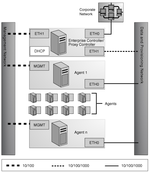
Combining the management and provisioning networks, as shown in Figure 7-9, reduces system and network security.
-
No additional NIC is needed on the Enterprise Controller or Proxy Controller.
Figure 7-9 Combined Management and Provisioning Network and a Separate Data Network
Description of "Figure 7-9 Combined Management and Provisioning Network and a Separate Data Network"
-
Enterprise Controller/Proxy Controller
-
ETH0 connects the Enterprise Controller/Proxy Controller to the corporate network to provide external access. Configure the ETH0 IP address, netmask, and gateway to meet corporate connectivity requirements.
-
ETH1 connects the Enterprise Controller/Proxy Controller to the management and provisioning network and must be on the same network as the MGMT and ETH0 connections of the Agent Controllers. Only the Enterprise Controller/Proxy Controller and the Agent Controllers must reside on the management and provisioning network. The ETH1 IP address, netmask, and gateway must be configured to enable connectivity to the Agent Controller's management port IP addresses. ETH1 must be a 1 Gb NIC interface.
-
The DHCP service allocates IP addresses to the Agent Controllers for provisioning operating systems.
-
-
Agent Controllers
-
Each Agent Controller's management port connects the Agent Controller to the management and provisioning network and must be on the same network as the ETH1 connection of the Enterprise Controller/Proxy Controller. The management port must be a 100 Mb connection.
-
ETH0 connects the Agent Controller to the management and provisioning network and must be on the same network as the ETH1 connection of the Enterprise Controller/Proxy Controller. ETH0 must be a 1 GB connection.
-
ETH1 connects the Agent Controller to the data network through the switch to provide corporate network access to the Agent Controller. ETH1 must be a 1-GB connection.
-
7.13.4 Combined Provisioning and Data Network and a Separate Management Network
Figure 7-10 shows a configuration with a network for both provisioning and data.
Figure 7-10 Combined Provisioning and Data Network and a Separate Management Network
Description of "Figure 7-10 Combined Provisioning and Data Network and a Separate Management Network"
-
Enterprise Controller/Proxy Controller
-
ETH0 connects the Enterprise Controller/Proxy Controller to the corporate network to provide external access. Configure the ETH0 IP address, netmask, and gateway to meet corporate connectivity requirements.
-
ETH1 connects the Enterprise Controller/Proxy Controller to the provisioning and data network and must be on the same network as the ETH0 connections of the Agent Controllers. Only the Enterprise Controller/Proxy Controller and the Agent Controllers must reside on the data and provisioning network. ETH1 must be a 1 Gb NIC interface.
-
ETH2 connects the Enterprise Controller/Proxy Controller to the management network and must be on the same network as the management port connections of the Agent Controllers. Configure the ETH2 IP address, netmask, and gateway to enable connectivity to the Agent Controller's management port IP addresses. ETH2 must be a 100 Mb NIC interface.
-
The DHCP service allocates IP addresses to the Agent Controllers for provisioning operating systems.
-
-
Agent Controllers
-
The management port connects the Agent Controller to the management network and must be on the same network as the ETH2 connection of the Enterprise Controller/Proxy Controller. The management port must be a 100 Mb connection.
-
ETH0 connects the Agent Controller to the data and provisioning network to provide corporate network access to the Agent Controller. ETH0 connection must be on the same network as the ETH1 connection of the Enterprise Controller/Proxy Controller. ETH0 must be a 1 GB connection.
-
7.13.5 Combined Provisioning, Data, and Management Network
-
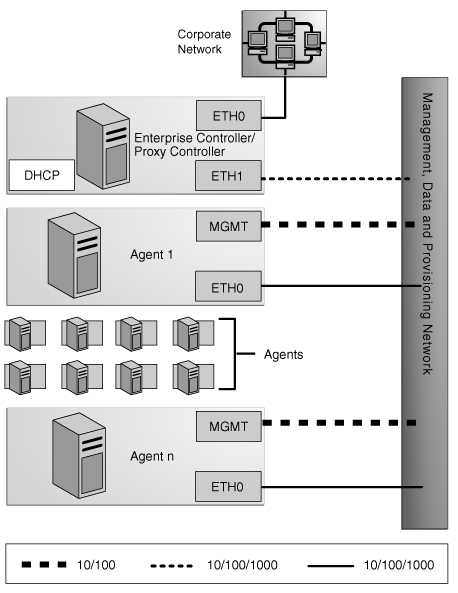
Figure 7-11 shows the least secure system and network.
-
No additional NIC is needed for the Enterprise Controller/Proxy Controller.
Figure 7-11 Combined Provisioning, Data, and Management Network
Description of "Figure 7-11 Combined Provisioning, Data, and Management Network"
-
Enterprise Controller/Proxy Controller
-
ETH0 connects the Enterprise Controller/Proxy Controller to the corporate network to provide external access. Configure the ETH0 IP address, netmask, and gateway to meet corporate connectivity requirements.
-
ETH1 connects the Enterprise Controller/Proxy Controller to the combined management, provisioning, and data network and must be on the same network as the MGMT and ETH0 connections of the Agent Controllers. Only the Enterprise Controller/Proxy Controller and the Agent Controllers must reside on the combined network. ETH1 must be a 1 GB NIC interface.
-
The DHCP service allocates IP addresses to the Agent Controllers for provisioning operating systems.
-
-
Agent Controllers
-
Each Agent Controller's management port connects the Agent Controller to the management, provisioning, and data network and must be on the same network as the ETH1 connection of the Enterprise Controller/Proxy Controller. The management port must be a 100 MB connection.
-
ETH0 connects the Agent Controller to the management, provisioning, and data network, and must be on the same network as the ETH1 connection of the Enterprise Controller/Proxy Controller. ETH0 also connects the Agent Controller to the data network through the switch to provide external corporate network access to the Agent Controller. ETH0 must be a 1 GB connection.
-
7.13.6 Firewall Rules
The Enterprise Controller must reach some external sites. If you have explicit firewall rules enabled to allow access to these services from your Enterprise Controller, you must update these rules to allow access to the addresses in Table 7-5.
Table 7-5 IP Address and Port Requirements
| Site | IP Address | Port | Purpose |
|---|---|---|---|
|
|
192.9.164.103 |
Port 443 |
Updates to OCDoctor utility |
|
|
192.9.164.103 |
Port 443 |
Access to Oracle Solaris Cluster profiles and scripts. |
|
|
141.146.8.119 |
Port 443 |
Logging into Oracle sites |
|
|
141.146.44.51 |
Port 443 |
Access to Oracle Knowledge Base for OS updates |
|
|
192.18.110.10 |
Port 443 |
Product registration |
|
|
192.18.110.11 |
Port 443 |
Product registration |
|
|
141.146.54.16 |
Port 443 |
My Oracle Support |
|
|
96.17.111.33 96.17.111.49 |
Port 80 |
- |
|
|
na |
Port 80 |
Provides local IP addresses to optimize download speed. Use |
|
|
na |
Port 443 |
Provides local IP addresses to optimize download speed. Use |
7.13.7 Network Port Requirements and Protocols
The Enterprise Controller's default port is 443. If port 443 is in use, the Enterprise Controller uses Port 11165. Table 7-6 describes all the required ports and their protocols.
Table 7-6 Required Ports and Protocols
| Communication Direction | Protocol and Port | Purpose |
|---|---|---|
|
Enterprise Controller |
Port 443, then Port 11165 Port 8005 |
Enterprise Controller in Disconnected mode |
|
Enterprise Controller |
Port 443, then Port 11165 |
Enterprise Controller in Connected mode |
|
Browser to Enterprise Controller |
HTTP, TCP: Port 80 |
Redirects to port 9443 |
|
Browser to Enterprise Controller |
HTTPS, TCP: Port 9443 |
Web interface |
|
Enterprise Controller to Local Database |
Port 11176 |
Oracle Listener port |
|
Enterprise Controller to Proxy Controller |
SSH, TCP: Port 22 ICMP ping: Type 8 Code 0 (echo request |
Enterprise Controller installs or upgrades a Proxy Controller through the UI. |
|
Proxy Controllers to Enterprise Controller |
HTTPS, TCP: Port 443 |
Proxy Controller pushes data about assets to Enterprise Controller. Proxy Controller pulls data for jobs, updates, Agent Controllers, and OS images from the Enterprise Controller. |
|
Proxy Controllers to Enterprise Controller |
HTTP: Port 8004 |
WAN Boot traffic |
|
Proxy Controllers to Enterprise Controller |
ICMP ping: Type 0 Code 0 (echo reply) |
During upgrades, Proxy Controllers use ICMP ping. |
|
Remote Proxy Controller to Enterprise Control through an SSH Tunnel |
SSH, Port 21161 |
When a Proxy Controller is deployed on a network outside of the firewall, the SSH Tunnel and Port 21161 change the direction of communication so that the remote Proxy Controller does not initiate communication with the Enterprise Controller. |
|
Proxy Controller to ALOM or XCSF Service Processors |
SSH, TCP: Port 22 or Telnet, TCP: Port 23 SNMP, UDP: Port 161 TCP: Port 6481 (for discovery by service tags) |
Proxy Controller discovers, manages, and monitors the service processor. |
|
Proxy Controller to ILOM Service Processors |
SSH, TCP: Port 22 SNMP, UDP: Port 161 IPMI, TCP, UDP: Port 623 TCP: Port 6481 (for discovery by service tags) |
Proxy Controller discovers, manages, and monitors the service processor. |
|
Proxy Controller to ALOM or XCSF Service Processor |
FTP, TCP: Port 21 |
Proxy Controller provisions firmware on an ALOM service processor. Port 21 transfers the firmware image. A transient random port is opened for the duration of the operation. |
|
Proxy Controller to ILOM Service Processor |
TFTP, UDP: Port 69 |
Proxy Controller provisions firmware on an ILOM service processor. Port 69 transfers the firmware image. A transient random port is opened for the duration of the operation. |
|
Service Processor to Proxy Controller |
SNMP, UDP: Port 162 ICMP ping: Type 0 (echo reply) |
For monitoring hardware, the service processor sends SNMP traps to the Proxy Controller. For a failed connection, Proxy Controller receives ICMP ping Type 3 (destination unreachable). |
|
Proxy Controller to OS Host |
SSH, TCP: Port 22 or Telnet, TCP: Port 23 TCP: Port 6481 (for discovery and monitoring by service tags) ICMP, Type 0 Code 0 (echo reply) |
Proxy Controller discovers, manages, and monitors an asset. |
|
Proxy Controller to OS Host |
DHCP, UDP: Port 67 |
Proxy Controller provisions an OS. |
|
OS Host to Proxy Controller |
HTTP, TCP: Port 8004 Oracle Solaris 11 Automated Installer Web Server: Port 5555 to accept requests from the OS Host during provisioning
|
OS Host reports status of OS updates and status of Agent Controller installation. OS Host downloads Agent Controller archive file. |
|
OS Host to Proxy Controller |
DHCP, UDP: Port 68 TFTP, UDP: Port 69 TCP+UDP: Port 37 HTTP, TCP: Port 8004 |
OS Host responds to Proxy Controller inquiries during bare-metal OS provisioning |
|
Agent Controller to Proxy Controller |
HTTPS, TCP: Port 21165 |
Agent Controllers push asset data to Proxy Controller. Agent Controllers pull data for jobs. |
|
Agent Controller to Proxy Controller |
HTTPS, TCP: Port 8002 |
Agent Controllers pull updates from Proxy Controller. |
|
Agent Controller on Oracle Solaris OS or on Oracle hardware to co-located Proxy Controller |
SNMP: Port 1162, or a port in the range of 1100 through 1200 |
For monitoring assets, the Agent Controller sends trap notifications and fault management alerts (FMA) to the Proxy Controller as local traffic. Because the Proxy Controller is using Port 162, a co-located Agent Controller uses Port 1162, if it is available, or a port in the range of Ports 1100 through 1200. |
|
Java client to public APIs |
TLS: Port 11172 |
JMX access from clients |
|
WMI client on Proxy Controller to Agent Controller |
Port 11162 |
WMI client resides on the Proxy Controller and communicates with the WMI server on the Agent Controller. The Proxy Controller uses the DCOM protocol to monitor a Windows system. The Proxy Controller opens a TCP connection to the Windows DCOM registry port, TCP 135, which provides a lookup service to the WMI scripting DCOM object. The Proxy Controller connects to the DCOM object. The port number for this connection is allocated by the Windows system. |
|
Proxy Controller to NFS server |
Use an NFS server that is on the same side of the firewall as the Proxy Controller. Refer to your OS documentation to set up the NFS server. |
Proxy Controller pulls provisioning images from NAS Library |
|
Global Zones or Oracle VM Servers to NFS server |
Use an NFS server that is on the same side of the firewall as the Proxy Controller. Refer to your OS documentation to set up the NFS server. |
Global Zones and Oracle VM Servers push their metadata and virtual host images to NAS Library |
|
OCDoctor to |
HTTPS, TCP: Port 80 |
Acquires product updates. |
7.14 Related Resources for Networks
For instructions in performing actions or to learn more about the role of this feature, go to one of the following resources.
-
For end-to-end examples, see the How To library at
http://docs.oracle.com/cd/E27363_01/nav/howto.htm -
For the Sun Ethernet 10GbE Fabric switch, see
http://docs.oracle.com/cd/E19934-01/index.html -
For Sun Datacenter InfiniBand switch and gateway, see
http://docs.oracle.com/cd/E19654-01/index.html