Examples of Protecting a VPN With IPsec by Using Tunnel Mode
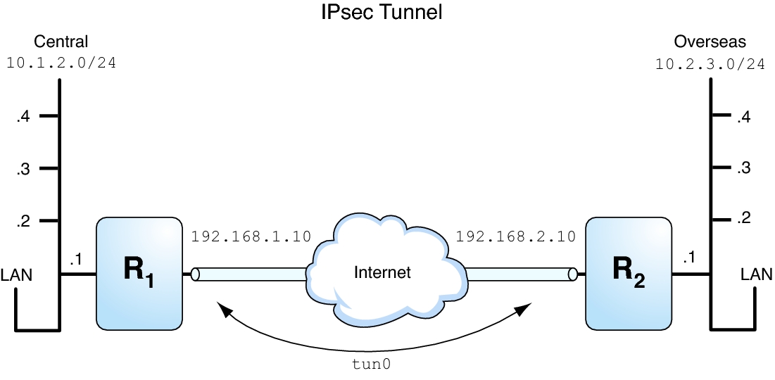
The tunnel in the following illustration is configured for all subnets of the LANs as follows:
## Tunnel configuration for ##
# Tunnel name is tun0
# Intranet point for the source is 10.1.2.1
# Intranet point for the destination is 10.2.3.1
# Tunnel source is 192.168.1.10
# Tunnel destination is 192.168.2.10
# Tunnel name address object is tun0/to-central
# Tunnel name address object is tun0/to-overseas
Figure 7-1 Tunnel Protected by IPsec

The following examples are based on the illustration.
Example 7-3 Creating a Tunnel That All Subnets Can UseIn this example, all traffic from the local LANs of the Central LAN in Figure 7–1 can be tunneled through Router 1 to Router 2, and then delivered to all local LANs of the Overseas LAN. The traffic is encrypted with AES.
## IPsec policy ##
{tunnel tun0 negotiate tunnel}
 ipsec {encr_algs aes encr_auth_algs sha512 sa shared}
Example 7-4 Creating a Tunnel That Connects Two Subnets
Only
In this example, only traffic between subnet 10.1.2.0/24 of the Central LAN and subnet 10.2.3.0/24 of the Overseas LAN is tunneled and encrypted. In the absence of other IPsec policies for Central, if the Central LAN attempts to route any traffic for other LANs over this tunnel, the traffic is dropped at Router 1.
## IPsec policy ##
{tunnel tun0 negotiate tunnel laddr 10.1.2.0/24 raddr 10.2.3.0/24}
 ipsec {encr_algs aes encr_auth_algs sha512 shared}