| Skip Navigation Links | |
| Exit Print View | |

|
Sun Blade X4-2B HTML Documentation Collection |
Sun Blade X4-2B Server Module Overview
Oracle System Assistant Overview
Oracle System Assistant Example
Oracle ILOM CMM Web Interface Example
About Server Module SP Oracle ILOM
Server Module SP Oracle ILOM Web Interface Example
Server Module SP Oracle ILOM CLI Example
1. Review Product Documentation
Sun Blade 6000 Modular System Documentation Library
Sun Blade X4-2B Documentation Library
2. Receive and Unpack the Server Module
3. Insert the Server Module Into a Chassis
4. Access Server Module Management Tools
Set Up Server Module Remote Using Ethernet Network Connection
Set Up Server Module Using Local Serial Connection
Set Up Server Module Using Local KVM Connection
Determining Server Module Oracle ILOM SP IP Address
Display Server Module Oracle ILOM SP IP Address (Web Interface)
Display Server Module Oracle ILOM SP IP Address (CLI)
Access Server Module SP Oracle ILOM
Log In to Oracle ILOM SP (Web Interface)
Log In to Oracle ILOM SP (CLI)
5. Set up Server Module Software and Firmware (Oracle System Assistant)
Accessing Oracle System Assistant
Launch Oracle System Assistant (Oracle ILOM)
Launch Oracle System Assistant (Locally)
Set Up Software and Firmware (Oracle System Assistant)
6. Configure Server Module Drives for OS Installation
Identifying REM Host Bus Adapters
SG-SAS6-R-REM-Z Host Bus Adapter
Configuring Storage Drives: SG-SAS6-R-REM-Z (Oracle System Assistant)
SG-SAS6-REM-Z Host Bus Adapter
Configure Storage Drives SG-SAS6-REM-Z (Oracle System Assistant)
Configure Storage Drives (LSI Configuration Utilities)
Configure Storage Drives (LSI WebBIOS Configuration Utility)
Set RAID Volume (Virtual Drive) as Bootable SG-SAS6-R-REM-Z HBA (LSI WebBIOS Utility)
Create a RAID Volume using LSI SAS 2 BIOS Configuration Utility
7. Set Up an Operating System and Drivers
Configuring Preinstalled Oracle Solaris OS
Preinstalled Oracle Solaris 11.1 Image BIOS Boot Mode Restriction
Preinstalled Operating System RAID Limitations
Oracle Solaris OS Documentation
Configure Preinstalled Oracle Solaris 11
Configuring Preinstalled Oracle VM Software
Preinstalled Oracle VM Image BIOS Boot Mode Restriction
Oracle VM Server Configuration Worksheet
Configure Preinstalled Oracle VM Server
Getting Started With Oracle VM
Configuring Preinstalled Oracle Linux OS
Preinstalled Oracle Linux Image BIOS Boot Mode Restriction
Oracle Linux Configuration Worksheet
Configure the Preinstalled Oracle Linux OS
Register and Update Your Oracle Linux OS
Registering Oracle Linux and Activating Automatic Update
Getting Server Firmware and Software Updates
Firmware and Software Access Options
Getting Firmware and Software From MOS or PMR
Download Firmware and Software Using My Oracle Support
Gathering Information for the Physical Media Request
Request Physical Media (Online)
Request Physical Media (By Phone)
Installing Updates Using Other Methods
Powering Off the Server Module
Graceful Shutdown (Power Button)
Graceful Shutdown (Oracle ILOM Web Interface)
Graceful Shutdown (Oracle ILOM CLI)
Immediate Shutdown (Power Button)
Immediate Shutdown (Oracle ILOM CLI)
Reset the Server (Oracle ILOM CLI)
Reset the Server (Oracle ILOM Web Interface)
Troubleshooting Installation Issues
Troubleshooting Server Power States
Technical Support Information Worksheet
Locating the Server Module Serial Number
Caution - Chassis shutdown hazard. Do not operate the chassis with empty slots for more than 60 seconds. Always insert a filler panel into an empty slot. If you are not installing a server module into a slot, do not remove a slot filler panel. The slot filler panel is required to meet FCC standards for electromagnetic interference (EMI). |
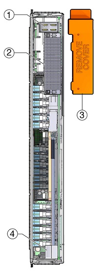
See Rear Panel Features for the location of the rear cover.
The following illustration shows rear panel features on the Sun Blade X4-2B.

|
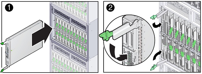
Caution - Drop hazard - Server modules can weigh up to 20 lbs (10kg). Use two hands to install or remove the server module from the chassis. |
Position the server module vertically so that the ejectors are on the right.

The server module is now locked in the chassis. After you install a server module into a powered-on chassis, the server module SP automatically boots using standby power from the chassis power supplies.
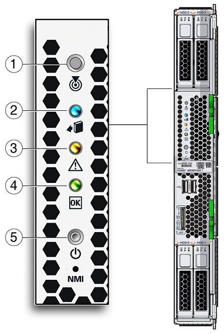
Verify that the server module front panel indicators illuminate after plugging in the server module:
The blade has been powered on and the SP boot process has begun.
The server module is in standby power mode after the SP completes its boot cycle.

|
Refer to the Sun Blade X4-2B Service Manual .
For more front panel information, see Front Panel Features. For additional information about server module indicators, LED lamp test, server module removal, power procedures, and front panel cable connections, refer to the Sun Blade X4-2B Service Manual .
Next Steps