JavaScript is required to for searching.
Skip Navigation Links
Exit Print View
Sun Blade X4-2B HTML Documentation Collection
Oracle Technology Network
Library
PDF
Print View
Feedback
search filter icon
search icon

Document Information

Using This Documentation

Hardware Installation

Operating System Installation

Service

Service Manual Overview

About the Sun Blade X4-2B

Product Description

About Front and Rear Panels

Front Panel Features

Front Panel Indicators and Buttons

Location of Front Panel Indicators and Buttons

Locate Indicator Button

Ready To Remove Indicator

Service Action Required Indicator

Power OK Indicator and Button

NMI Button

Rear Panel of the Server Module

UCP and the Multi-Port Dongle Cable

Attach the Multi-Port Dongle Cable

About the Chassis

The System Chassis

The Chassis Monitoring Module (CMM)

About Oracle ILOM

About System Components

Illustrated Parts Breakdown

Replaceable Components (FRUs and CRUs)

Component Serviceability

Troubleshooting the Server Module

Troubleshooting Server Module Hardware Faults

Service Troubleshooting Task List

Troubleshoot Hardware Faults

Diagnostic Tools

Troubleshooting and Diagnostic Information

Gather Service Information

Locate the Server Module Serial Number

Troubleshoot Server Module Power Problems

About the DIMM and Processor Test Circuit

Recover the SP Firmware Using the Preboot Menu (Service Only)

Preparing for Service

Preparing the Server Module for Component Replacement

Powering Down the Server Module

About Server Power States and Resets

Full Power

Standby Power

Graceful Shutdown

Immediate Shutdown

Complete Power Removal

Warm Reset or Reboot

Cold Reset

Power Off, Graceful (Power Button)

Power Off, Immediate (Power Button)

Power Off, Remote (Oracle ILOM CLI)

Power Off, Remote (Oracle ILOM Web Interface)

Remove Power Completely

Performing ESD and Anti-static Prevention Measures

Use an Anti-static Wrist Strap and an Anti-static Mat

Set Up for ESD Prevention

Remove the Server Module from the Sun Blade Chassis

Server Module and Component Filler Panels

Install Server Module Filler Panels

Remove the Server Module Top Cover

Turning the Locate Indicator On and Off

Turn On the Locate Indicator Remotely (Oracle ILOM CLI)

Turn On the Locate Indicator Remotely (Oracle ILOM Web Interface)

Turn the Locate Indicator On and Off Locally

Required Tools

FRU TLI Auto-Update

Servicing Server Module Components

Servicing a Storage Drive (CRU)

Identifying Storage Drives

Identifying Storage Drive Indicators and Mechanical Components

Ready to Remove Indicator

Service Action Required Indicator

Power/OK Indicator

Lever and Lever Release Button

Storage Drive Failure and RAID

About Disk Backplane Cabling

Remove a Storage Drive

Install a New Storage Drive

Replace a Storage Drive

Remove Storage Drive Filler Panels

Insert Storage Drive Filler Panels

Servicing DIMMs (CRU)

DIMM Fault Remind Circuit and ECC Errors

Fault Remind Button and Charge Status Indicator

DIMM Fault Indicators

Inconsistencies Between DIMM Fault LEDs and the BIOS Isolation of Faulty DIMMs

Error Correction and Parity

Identify Faulty DIMMs

DIMM Population Rules and Guidelines

Basic Memory Guidelines

Detailed Memory Population Rules

Remove DIMMs

Install DIMMs

Servicing USB Flash Sticks (CRU)

Remove USB Flash Sticks

Install USB Flash Sticks

Servicing a Fabric Expansion Module (CRU)

Remove a FEM

Install a FEM

Servicing a RAID Expansion Module (CRU)

Remove a REM Card

Install a REM Card

Replace a REM Battery on the REM Card

Servicing Processors (FRU)

Selecting the Correct Processor Removal/Replacement Tool

Processor Fault Remind Circuit

Fault Remind Button and Charge Status Indicator

Processor Fault Indicators

Identify a Faulty Processor

Remove a Processor Heat Sink (FRU)

Remove a Processor (FRU)

Install a Processor (FRU)

Install a Processor Heat Sink (FRU)

Servicing the Motherboard Assembly (FRU)

Remove Motherboard Assembly Components (FRU)

Install Motherboard Assembly Components (FRU)

Update FRUID (Service Only)

Servicing the System Battery (CRU)

Returning the Server Module to Operation

Return the Server Module to Operation

Install the Server Module Top Cover

Remove Server Module Filler Panel

Install the Server Module in the Chassis

Powering On the Server Module

Power On Using the Power Button

Power On (Oracle ILOM SP CLI)

Power On (Oracle ILOM SP Web Interface)

Clear Server Module Faults

BIOS Power-On Self-Test (POST) Checkpoints

POST Code Checkpoint Memory Testing

Viewing POST Code Checkpoints

View BIOS POST Code Checkpoints (Oracle ILOM Web Interface)

View BIOS POST Code Checkpoints (Oracle ILOM CLI)

POST Code Checkpoint Reference

Checkpoint Ranges

Standard Checkpoints: SEC Phase

Standard Checkpoints: PEI Phase

Standard Checkpoints: DXE Phase

ACPI/ASL Checkpoints

OEM-Reserved Checkpoint Ranges

BIOS Setup Utility Menu Options

BIOS Main Menu Selections

BIOS Advanced Menu Selections

BIOS I/O Menu Selections

BIOS Boot Menu Selections

BIOS Save and Exit Menu Selections

Index

BIOS I/O Menu Selections

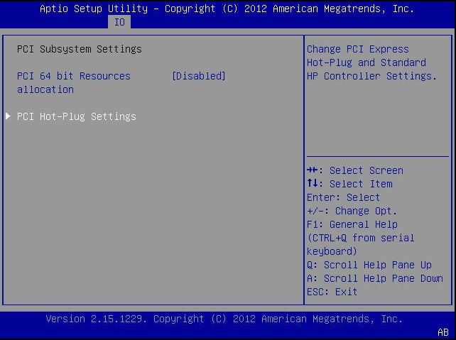
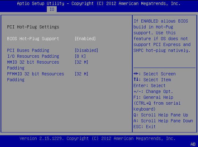
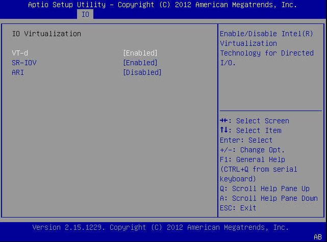
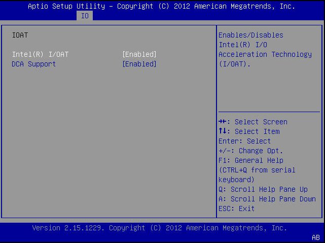
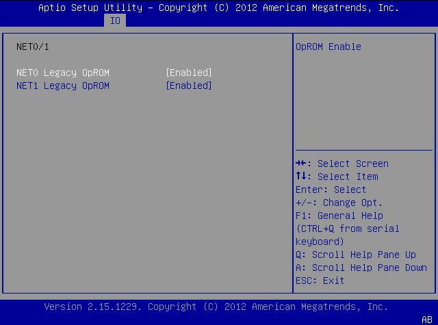
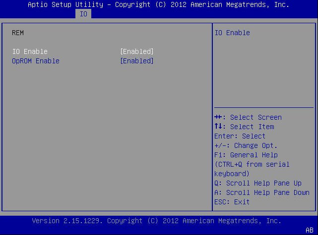
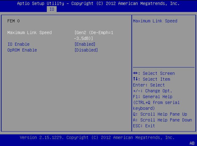
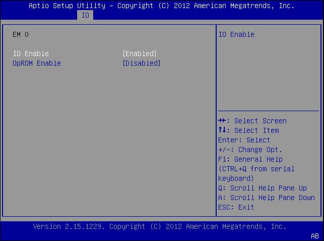
The following screen captures show the BIOS Setup Utility I/O menu screens.

image:A screen capture showing the BIOS Setup Utility I/O menu screen.

The following table lists the BIOS Setup Utility I/O menu setup options:

I/O Setup Options
Options
Defaults
Description
PCI SUBSYSTEM SETTINGS
Configure PCI, PCI-X, and PCI Express settings.
PCI 64 Bit Resources Allocation
Disabled/ Enabled
Disabled
Enable or disable 64-bit capable devices to be decoded in above 4G address space. This setting is available only if the system supports 64-bit decoding.
IO VIRTUALIZATION
Configure VT-d, SR-IOV, and ARI virtualization settings.
VT-d
Disabled/ Enabled
Enabled
Enable or disable Intel Virtualization Technology for directed I/O (VT-d). If enabled, ensures improved isolation of I/O resources for greater reliability, security, and availability.
SR-IOV
Disabled/ Enabled
Enabled
Single Root I/O Virtualization (SR-IOV) is used to configure devices into multiple virtual devices that can be used on virtual OS installations. If supported by the hardware and set to enabled, all devices within the system that are SR-IOV capable are configured to support SR-IOV and I/O resources are allocated to the device as normal. If set to disabled, I/O resources are not allocated to the device.
ARI
Disabled/ Enabled
Enabled
If Alternate Routing ID (ARI) is supported by the hardware and set to enabled, devices are permitted to locate virtual functions (VFs) in function numbers 8 to 255 of the captured bus number, instead of normal function numbers 0 to 7.
I/OAT
Configure settings for the Intel I/O Acceleration Technology (I/OAT).
Intel I/OAT
Disabled/ Enabled
Enabled
Enable or disable Intel I/OAT.
DCA Support
Disabled/ Enabled
Enabled
Enable or disable direct cache access (DCA) support.
INTERNAL DEVICES
Configure settings for the embedded network controller.
NET0/1 OpROM Enable
Disabled/ Enabled
Enabled
Enable or disable Option ROM. If set to enabled, Option ROM for the card executes as normal. If set to disabled, Option ROM for the card is not copied into memory and the execution of the Option ROM is inhibited.
NET2 and NET3 OpROM Enable
Note - Ethernet ports NET2 and NET3 are nonfunctional in single-processor systems.
Disabled/ Enabled
Enabled
Enable or disable Option ROM. If set to enabled, Option ROM for the card executes as normal. If set to disabled, Option ROM for the card is not copied into memory and the execution of the Option ROM is inhibited.
ADD-IN CARDS
Enable or disable the add-in cards:
REM
FEM 0
FEM 1
EM 0
EM 1
REM
IO Enable
Disabled/ Enabled
Enabled
Enable or disable I/O for the add-in card.
OpROM Enable
Disabled/ Enabled
Enabled
Enable or disable Option ROM for the add-in card.
FEM 0
IO Enable
Disabled/ Enabled
Enabled
Enable or disable I/O for the add-in card.
OpROM Enable
Disabled/ Enabled
Enabled
Enable or disable Option ROM for the add-in card..
FEM 1
IO Enable
Disabled/ Enabled
Enabled
Enable or disable I/O for the add-in card.
OpROM Enable
Disabled/ Enabled
Enabled
Enable or disable Option ROM for the add-in card.
EM 0
IO Enable
Disabled/ Enabled
Enabled
Enable or disable I/O for the add-in card.
OpROM Enable
Disabled/ Enabled
Enabled
Enable or disable Option ROM for the add-in card.
EM 1
IO Enable
Disabled/ Enabled
Enabled
Enable or disable I/O for the add-in card.
OpROM Enable
Disabled/ Enabled
Enabled
Enable or disable Option ROM for the add-in card.
Maximum Link Speed
Displays speed as [GEN2 (De-Emph=1 -3.5 dB]
PCI Hot-Plug Settings
Change PCI Express and standard HP controller settings.
If enabled allows BIOS built in hot-plug support. Use this feature if OS does not support PCI Express and SHPC hot-plug natively.
Use this feature to enable or disable PCI Hot-Plug Settings:
BIOS Hot-Plug Support
PCI Buses Padding
I/O Resources Padding
MMIO 32 bit Resources Padding
PFMMIO 32 bit Resources Padding
PCI Buses Padding
Disabled/ Enabled
Disabled
Use this feature if OS does not support PCI Express and SHPC hot-plug natively.
I/O Resources Padding.
8 k
Use this feature if OS does not support PCI Express and SHPC hot-plug natively.
MMIO 32 bit Resources Padding.
32 M
Use this feature if OS does not support PCI Express and SHPC hot-plug natively.
PFMMIO 32 bit Resources Padding.
32 M
Use this feature if OS does not support PCI Express and SHPC hot-plug natively.
Legacy iSCSI
Configure the iSCSI parameters.
Launch Legacy iSCSI
Disabled/ Enabled
Disabled
Enable or disable iSCSI for the add-in card.
image:A screen capture showing the BIOS Setup Utility I/O menu screen. image:A screen capture showing the BIOS Setup Utility I/O menu screen. image:A screen capture showing the BIOS Setup Utility I/O menu screen. image:A screen capture showing the BIOS Setup Utility I/O menu screen. image:A screen capture showing the BIOS Setup Utility I/O menu screen. image:A screen capture showing the BIOS Setup Utility I/O menu screen. image:A screen capture showing the BIOS Setup Utility I/O menu screen. image:A screen capture showing the BIOS Setup Utility I/O menu screen.