Determining the Number of Rooms in Your Cluster
The concept of a room, or location, adds a layer of complexity to the task of designing a campus cluster. Think of a room as a functionally independent hardware grouping, such as a node and its attendant storage, or a quorum device that is physically separated from any nodes. Each room is separated from other rooms to increase the likelihood of failover and redundancy in case of accident or failure. The definition of a room therefore depends on the type of failure to safeguard against, as described in the following table.
|
Oracle Solaris Cluster does support two-room campus clusters. These clusters are valid and might offer nominal insurance against disasters. However, consider adding a small third room, possibly even a secure closet or vault (with a separate power supply and correct cabling), to contain the quorum device or a third server.
Whenever a two-room campus cluster loses a room, it has only a 50 percent chance of remaining available. If the room with fewest quorum votes is the surviving room, the surviving nodes cannot form a cluster. In this case, your cluster requires manual intervention from your Oracle service provider before it can become available.
The advantage of a three-room or larger cluster is that, if any one of the three rooms is lost, automatic failover can be achieved. Only a correctly configured three-room or larger campus cluster can guarantee system availability if an entire room is lost (assuming no other failures).
Three-Room Campus Cluster Examples
A three-room campus cluster configuration supports up to eight nodes. Three rooms enable you to arrange your nodes and quorum device so that your campus cluster can reliably survive the loss of a single room and still provide cluster services. The following example configurations all follow the campus cluster requirements and the design guidelines described in this chapter.
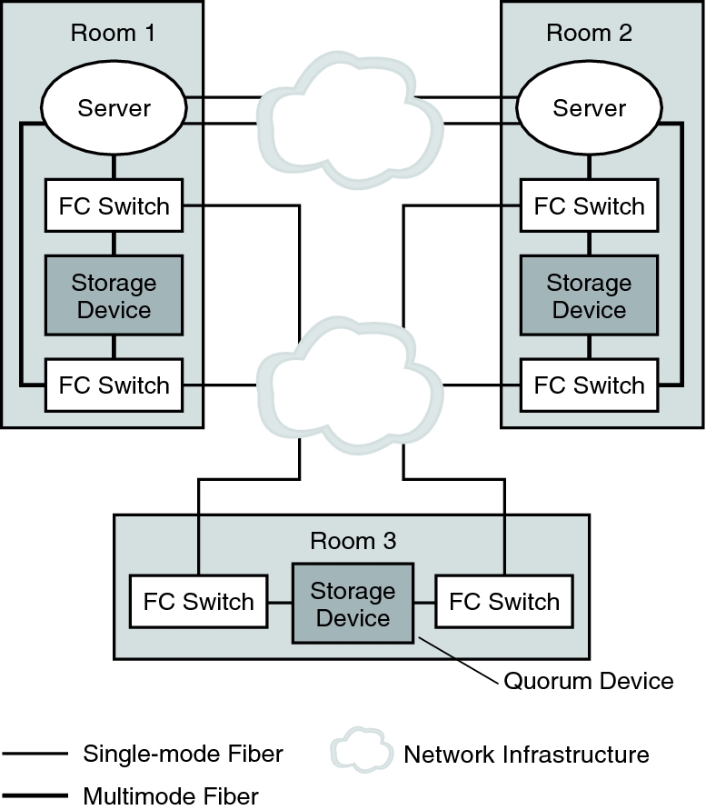
Figure 7–1 shows a three-room, two-node campus cluster. In this arrangement, two rooms each contain a single node and an equal number of disk arrays to mirror shared data. The third room contains at least one disk subsystem, attached to both nodes and configured with a quorum device.
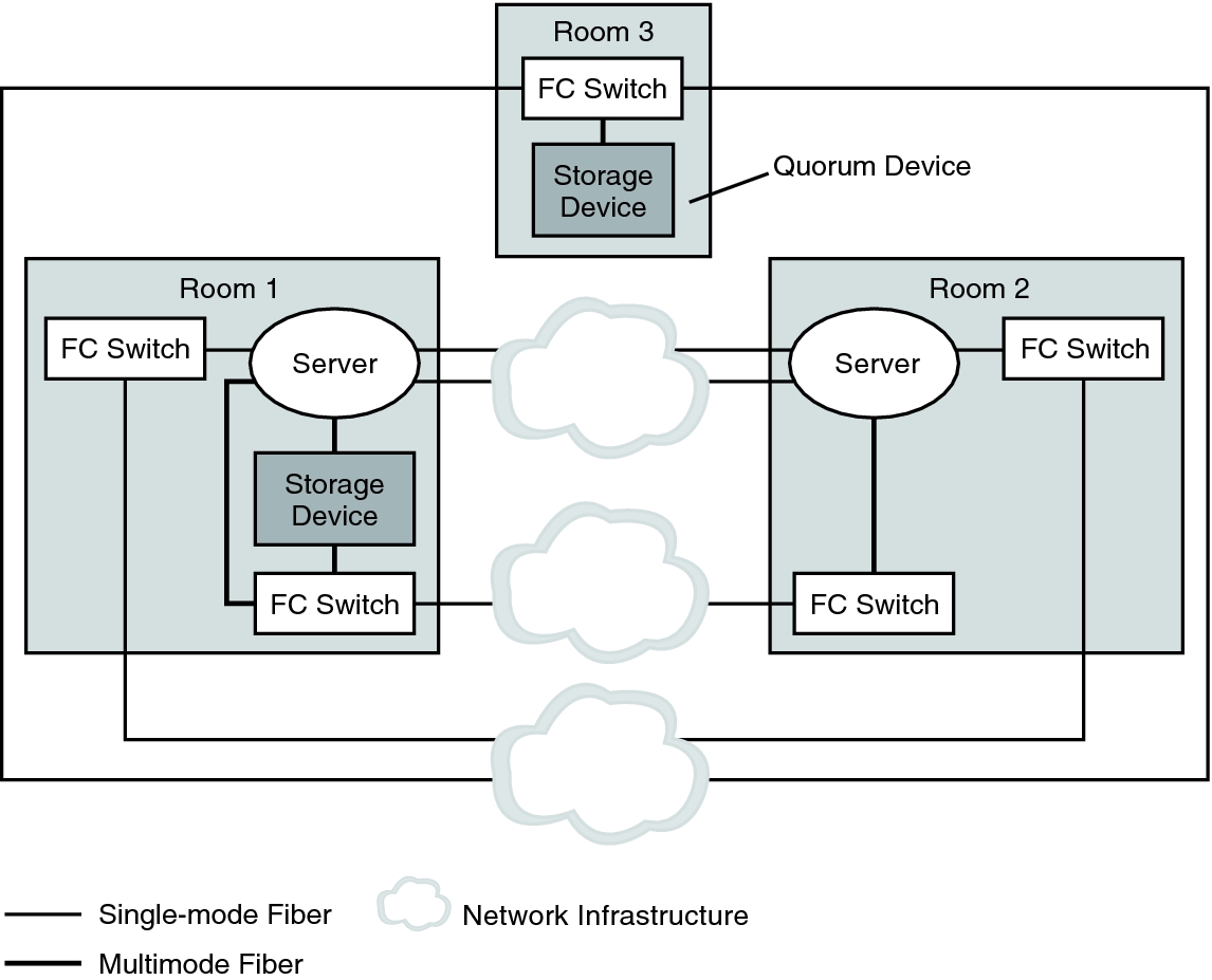
Figure 7–2 shows an alternative three-room, two-node campus cluster.
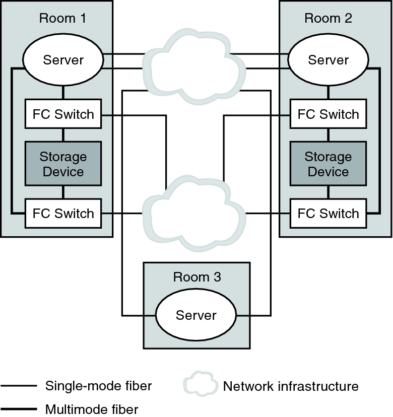
Figure 7–3 shows a three-room, three-node cluster. In this arrangement, two rooms each contain one node and an equal number of disk arrays. The third room contains a small server, which eliminates the need for a storage array to be configured as a quorum device.
Note - These examples illustrate general configurations and are not intended to indicate required or recommended setups. For simplicity, the diagrams and explanations concentrate only on features that are unique to understanding campus clustering. For example, public-network Ethernet connections are not shown.
Figure 7–1 shows a three-room, two-node campus cluster.
Figure 7-1 Basic Three-Room, Two-Node Campus Cluster Configuration With Multipathing

In Figure 7–2, if at least two rooms are up and communicating, recovery is automatic. Only three-room or larger configurations can guarantee that the loss of any one room can be handled automatically.
Figure 7-2 Minimum Three-Room, Two-Node Campus Cluster Configuration Without Multipathing

In Figure 7–3, one room contains one node and shared storage. A second room contains a cluster node only. The third room contains shared storage only. A LUN or disk of the storage device in the third room is configured as a quorum device.
This configuration provides the reliability of a three-room cluster with minimum hardware requirements. This campus cluster can survive the loss of any single room without requiring manual intervention.
Figure 7-3 Three-Room, Three-Node Campus Cluster Configuration

In Figure 7–3, a server acts as the quorum vote in the third room. This server does not necessarily support data services. Instead, it replaces a storage device as the quorum device.