| Oracle Virtual Operator Panel User's Guide Release 2.1 E48640-01 |
|


 Previous |
 Next |
This chapter describes how to use the MD-VOP Dashboard menus.
Use MD-VOP Dashboard menu commands to create or edit an MD-VOP configuration, and to specify application settings. A configuration applies to the libraries and tape drives that are to be displayed in the Drive Details section of the Library Panel.
The Dashboard includes a File Menu and Help Menu.
The File menu includes the following commands:
Displays a pop-up window you can use to open a previously saved local configuration.
Displays the Configuration screen, used to create a new configuration or edit and existing configuration. See "Using the MD-VOP Configuration Screen" for more information.
Displays a sub-menu of options used to configure the MDVOP server component. See "Using the MDVOP Server Menu Options" for more information.
Set as Default Configuration File
Sets the current configuration as the default. This configuration is automatically loaded the next time you start MD-VOP.
Edit Library Probe Configuration
Displays the Library Probe Configuration dialog box, used to set defaults for establishing communication with a tape library. These defaults are applied on the Configuration screen when you enter the IP address for an SL500, SL3000, or SL8500 library.
Enter the following default library probe settings:
Default User
The account used to connect to a library. Enter an account or select one of the following from the drop-down menu:
admin - The general administration account provided to you.
remote - Remote user for libraries.
acsss - Placeholder for future ACSLS functionality.
oem - An OEM account from a partner. Also used for libraries.
Default Password
The password for the default account. Once you connect to a library, you can change the password to be specific to that library.
Unknown Host Authorization
Applies when using SSH for communication. Library credentials can be displayed for you to accept or decline.
Select one of the following from the drop-down menu:
Auto - SSH credentials are not displayed, and are automatically accepted.
Prompt - SSH credentials are displayed and you are prompted to accept or decline.
Connection Timeout
The timeout value, in seconds, for the connection within SSH while establishing a connection to the library.
Process Execution Timeout
The timeout value, in seconds, for an individual command being sent.
Displays the Default Settings screen, used to edit MD-VOP display settings. See "Changing MD-VOP Default Settings" for more information.
Collects all MD-VOP logs and saves them in a zip file at the specified location.
Launches an existing configuration. The five most recent configurations are listed.
Launch Single Drive T10000/9840D VOP
Launches the T10000/9840D VOP in a new window.
Launch Single Drive LTO VOP
Launches the LTO VOP in a new window.
Launch Single Drive 9XXX VOP
Launches the 9XXX VOP in a new window.
Exits the MD-VOP application.
|
Note: You can also click the ”X” icon in the upper right corner of the window to exit the MD-VOP application. |
The Help menu includes the following commands:
Displays a warranty statement and information about contacting Oracle to obtain MD-VOP support.
Displays the following information about the MD-VOP application and environment:
Role level access
MD-VOP Version
MD-VOP Build Date
VOP Version
VOP Build Date
Java Version
License Agreement
From the Dashboard, click the File menu and select Edit Configuration to access the Configuration screen.
Use this screen to create a new MD-VOP configuration, or edit an existing MD-VOP configuration. You can also use this screen to find a tape drive, probe a range of IP addresses, or change the IP address of a tape drive.
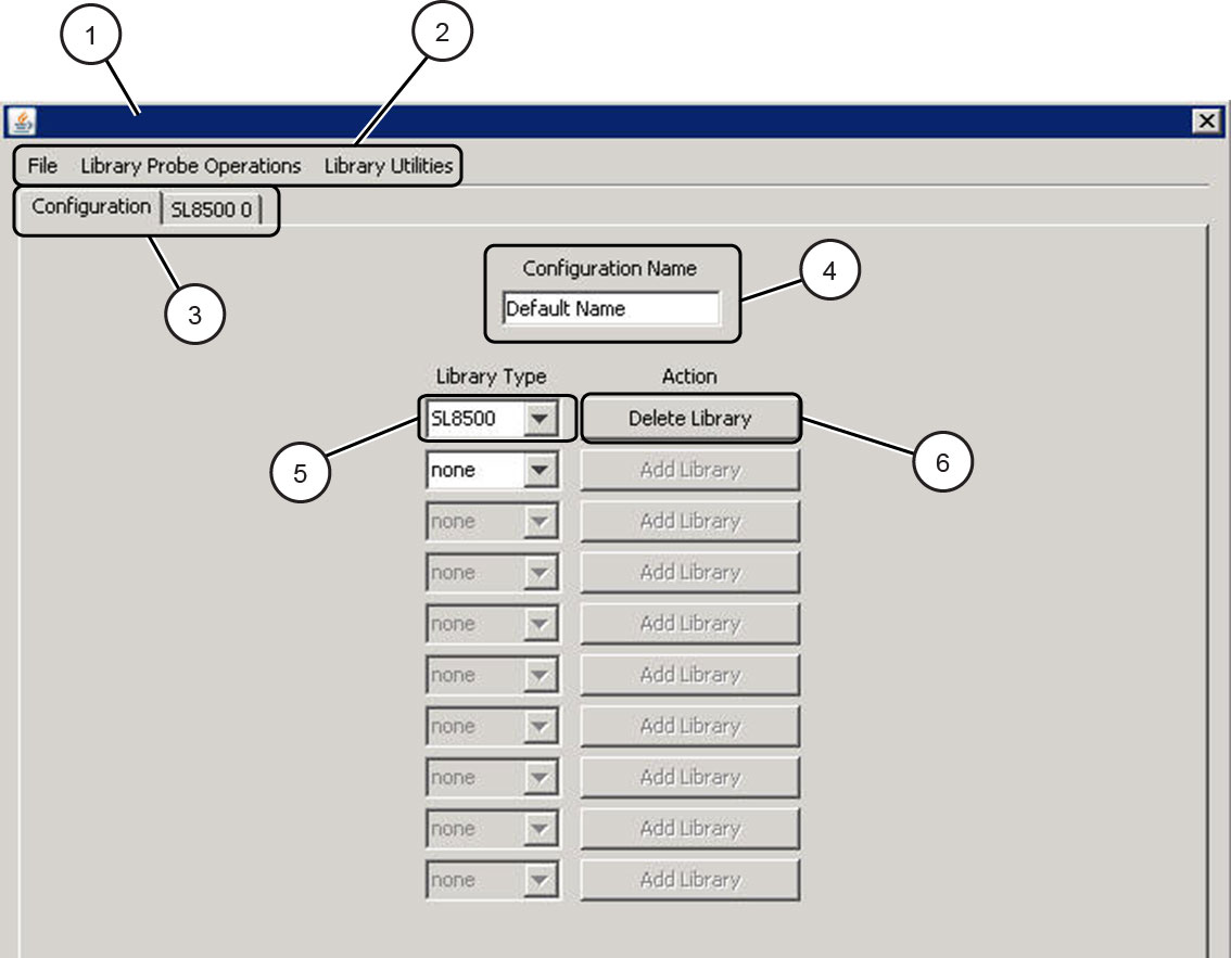
Figure 8-1 shows the Configuration screen:
Legend:
1. Title
2. Menus
3. Tabs
4. Configuration Name
5. Library Type
6. Action
As shown in Figure 8-1, the Configuration screen includes the following:
Title
The file name used to create this configuration.
Menus
Use menus to issue MD-VOP configuration commands. See "Configuration Menus" for more information.
Tabs
A Configuration tab is displayed, along with additional tabs for each library you add. click a library tab to display its Library Spreadsheet page, where you can define detailed settings for the library. See "Library Spreadsheet Page" for more information.
Configuration Name
The configuration name as displayed on the MD-VOP dashboard.
When you create a new MD-VOP configuration, Default Name is displayed. Overwrite this value with your new configuration name.
Library Type drop-down menu
Click this drop-down menu to select a library type to be added or deleted. This selection defines the possible types of slots available.
Action
Click this button to add or remove a library from the MD-VOP configuration.
When you add a library, a new tab is created, and the Library Spreadsheet page for the new library is displayed. Use this page to define your library settings. See "Library Spreadsheet Page" for more information.
When you delete a library, all entries for that library are removed.
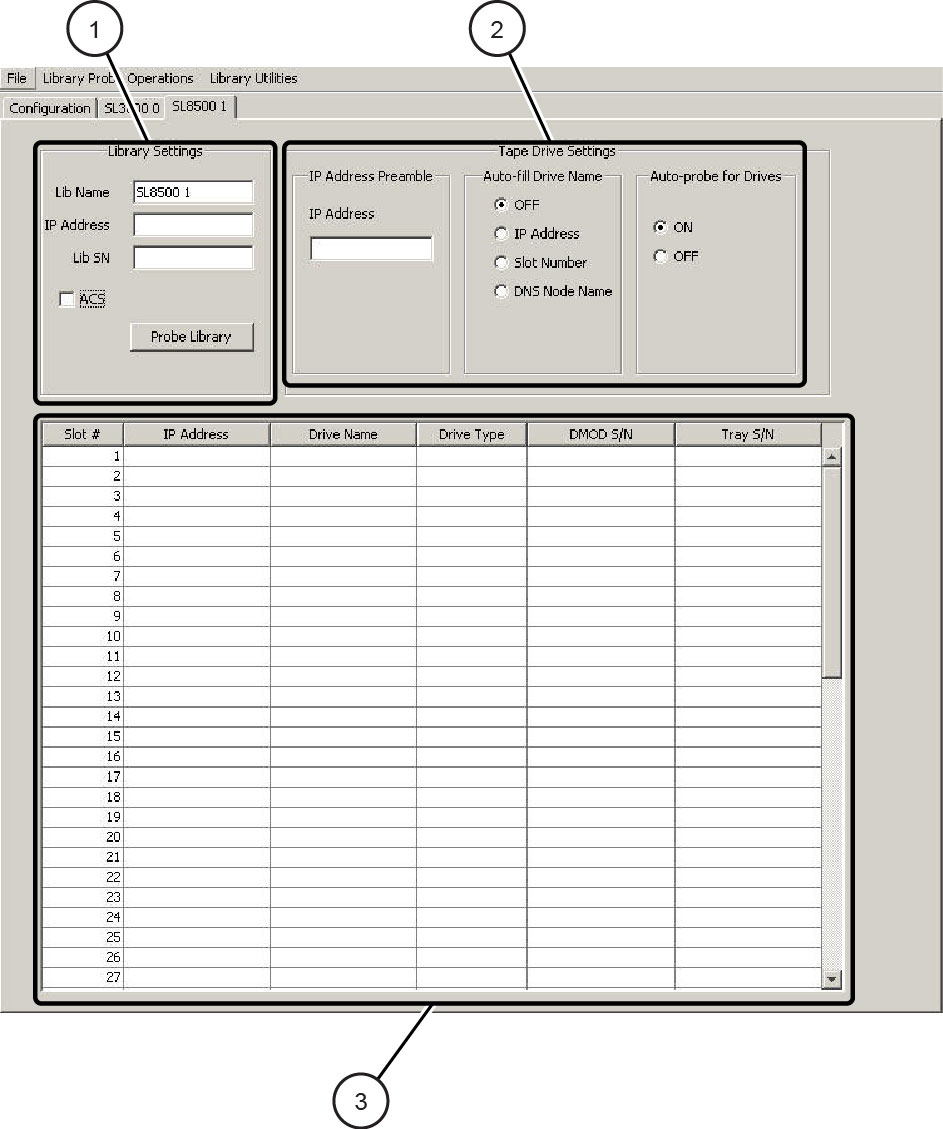
To display the Library Spreadsheet page for a particular library, click the appropriate library tab from the MD-VOP Configuration screen. Use the Library Spreadsheet page to define or view detailed library settings.
Figure 8-2 shows an example of the Library Spreadsheet page.
Legend:
1. Library Settings
2. Tape Drive Settings
3. Drive Definition Spreadsheet
As shown in Figure 8-2, the Library Spreadsheet page is divided into three sections:
The Library Spreadsheet page includes the following library settings:
Lib Name
Specify the library name. This is used as the user-defined library name.
Number of Drive Bays (SL3000 only)
Specify the number of optional tape drive modules.
IP Address
Specify the IP address for the library.
Lib SN
Specify the serial number for the library.
Click the Probe button to perform a probe based on the specified settings. Once the probe completes, the Library Spreadsheet is automatically populated with the results of the probe.
The Library Spreadsheet page includes the following tape drive settings:
IP Address Preamble
Optionally, enter the first three fields of the tape drive IP address. This will be used as the preamble for the IP specification in the second column of the Drive Definition spreadsheet. This preamble will be appended to that specification to form the complete IP address.
Auto-fill Drive Name
Use these options to automatically populate the Drive Name column of the Drive Definition spreadsheet:
Off
Do not attempt to automatically populate the Drive Name column.
IP Address
Use the IP address as the default name in the Drive Name column.
Slot Number
Use the slot location as the default name in the Drive Name column.
DNS Node Name
Use the DNS entry for the IP address (if detected) as the default name in the Drive Name column.
Auto-probe for drives
Direct MD-VOP to probe for drive type and serial number when you enter an IP address on the Drive Definition spreadsheet. Click ON to enable this feature. Click OFF to disable this feature.
The Drive Definition spreadsheet includes six columns:
Slot number
The library slot in which the tape drive is located.
IP Address
The IP address of the tape drive.
Drive Name
Human readable name of the tape drive. This field can be user entered.
Drive Type (special)
The model of the tape drive in this slot. The value of this field determines which connection protocol and single-drive VOP style to use when connecting to this tape drive:
Telnet
T10000 family, T9840D. Detected by probe operation.
LTO
Ethernet-enabled encryption HP and IBM LTO4/5. Detected by probe operation.
FTP
T9840B/C, T9940B. Detected by probe operation.
Placeholder
Indicates that a non-Ethernet connected tape drive is in this library location. For example, LTO2, LTO3, etc. This field must be manually entered.
DMOD S/N
The serial number for the tape drive in this library slot.
Tray S/N
The serial number of the tray for the tape drive in this library slot.
The drive definition spreadsheet must include a populated row for each tape drive in the library. To populate the spreadsheet, do one of the following:
Specify library settings and click the Probe button.
If you enable the Auto-probe for drives option, you can enter an IP address in the spreadsheet and allow MD-VOP to probe for the drive. Once the drive is detected, the remaining columns are automatically populated.
Use configuration menu commands to select a range and probe for multiple IP addresses. Once IP addresses are detected, the spreadsheet columns are automatically populated.
See "Using Probe Commands" for more information.
When you are finished entering tape drives on the spreadsheet, click the next empty row in the spreadsheet to signal to MD-VOP that the last row is complete. Then click the File menu and select Save to save your configuration.
The following configuration menus are displayed at the top of the Configuration screen:
The File menu includes the following commands:
Opens an existing configuration.
Creates a new, ”empty” configuration with no libraries or tape drives. The current configuration is not affected.
Saves the configuration.
Saves the configuration with a specified name.
Deletes the configuration.
Sets the current configuration as the default configuration that is loaded when you start MD-VOP.
Clears the default configuration setting.
Launches an existing configuration. The five most recent configurations are listed.
Exits the Configuration screen.
Use the Library Probe Operations menu to populate tape drive information in the active library spreadsheet page.
This menu includes the following commands:
Probe IP Addresses in Spreadsheet
If an IP address is present in column 1, probe for a valid device.
|
Note: The auto probe routine (enabled by default) performs the same function. For valid IP addresses, the Drive Type and Drive Serial Numbers will be automatically populated. See "Tape Drive Settings" for more information about the Auto-probe for drives routine. |
Probes tape drives for a single library, based on an IP range. See "Probing an IP Range for Drives".
Probes a library based on the specified library IP address and automatically populates the drive information in the Library Spreadsheet.
Use the Library Probe Operations menu to direct MD-VOP to probe for a collection of SL8500 libraries connected with pass-through ports.
MD-VOP creates the libraries that can be detected from information reported by tape drives, and inserts the tape drives in the appropriate library.
This option is only valid for T10000 tape drives. These tape drives must be at appropriate firmware levels. See "MD-VOP Tape Drive Support" for more information.
|
Note: This option is recommended only for new, ”empty” configurations. Using this option with an existing configuration can result in mismatches and duplicate information. |
See "Probing a Complex" for information about performing the probe.
This menu includes the following commands:
Clears all entries in the current drive definition spreadsheet. All entries are stored until you save the configuration.
Reset Probe Settings for this Library
Clears all entries in the current drive definition spreadsheet. All entries are stored until you save the configuration.
Clears all entries in the current drive definition spreadsheet. All entries are stored until you save the configuration.
Allows you to enter a serial number for a selected slot. This serial number is used when requesting support. It is included in reports, and in the information displayed when you mouse-over a tape drive.
This command loops through each tape drive present and requests that the tray serial number be added to the drive definition spreadsheet. For each slot, enter the serial number and press the OK button.
|
Note: You can also manually add these serial numbers to the drive definition spreadsheet. |
MD-VOP includes Probe commands designed to help you build an MD-VOP configuration. These commands probe for libraries and tape drives, and then create and populate the corresponding library spreadsheet pages.
Access these commands from the Library Probe Operations menu on the MD-VOP Configuration screen.
Use the Library Probe Operations menu to direct MD-VOP to probe for a collection of SL8500 libraries connected with pass-through ports. MD-VOP creates the libraries that can be detected from information reported by tape drives, and inserts the tape drives in the appropriate library.
This option is only valid for T10000 tape drives. These tape drives must be at appropriate firmware levels.
Additionally, this option is recommended only for new, ”empty” configurations. Using this option with an existing configuration can result in mismatches and duplicate information.
To probe an SL8500 library complex:
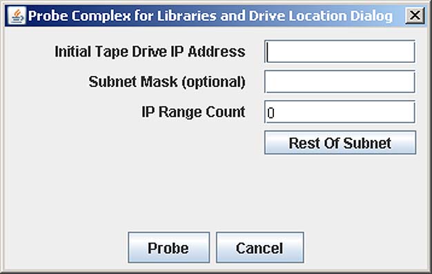
Click the Library Probe Operations menu and select Probe Complex (SL8500 Only). A pop-up window appears:
Enter the Initial Tape Drive IP Address. Optionally, you may include the number of bits in the subnet mask. For example, 172.18.18.1/23.
Optionally, enter the number of bits in the subnet mask. This is an alternative to the method described in the previous step.
Enter the IP range count to scan from the base address. Click the Rest of Subnet button to automatically change the IP count to extend to the last IP address in the subnet.
Click the Probe button.
A status window appears as MD-VOP begins to probe each IP address in the specified range to locate any tape drives. During this process, MD-VOP scans the IP range, creates libraries, and places detected tape drives into the correct library and slot location.
If you wish to cancel this operation, click the Abort Probe button at any time.
When the probe completes, an informational window appears, indicating the number of tape drives that were located and placed and the number of tape drives that were unable to be placed.
|
Note: You can manually enter the unsuccessful tape drives. |
Click OK. MD-VOP creates a new tab in the Library Panel for each library detected. In addition, the drive definition spreadsheet for each library is automatically populated with the valid tape drive information.
Use the Library Probe Operations menu to direct MD-VOP to probe for tape drive IP addresses within a selected library.
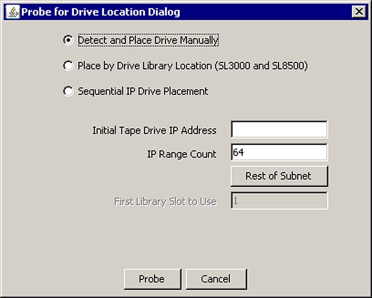
Click Library Probe Operations and select Probe IP Range for Drives. The following pop-up window appears:
This window includes radio buttons used to select one of the following probing methods:
Detect and Place Drive Manually
MD-VOP probes for tape drives and allows you to place them manually.
Place by Drive Library Location SL3000 and SL8500)
MD-VOP probes for tape drives and places them in the appropriate slots.
Sequential IP Drive Placement
MD-VOP probes for tape drives and places them sequentially by slot.
These methods are described in the following sections.
To perform the probe:
Click Library Probe Operations and select Probe IP Range for Drives. The Probe for Drive Location dialog box appears.
Click Detect and Place Drive Manually radio button.
In the Initial Tape Drive IP Address field, enter the starting IP address.
In the IP Range Count field, specify an IP Range Count or click the Rest of Subnet button to automatically change the IP count to extend to the last IP address in the subnet.
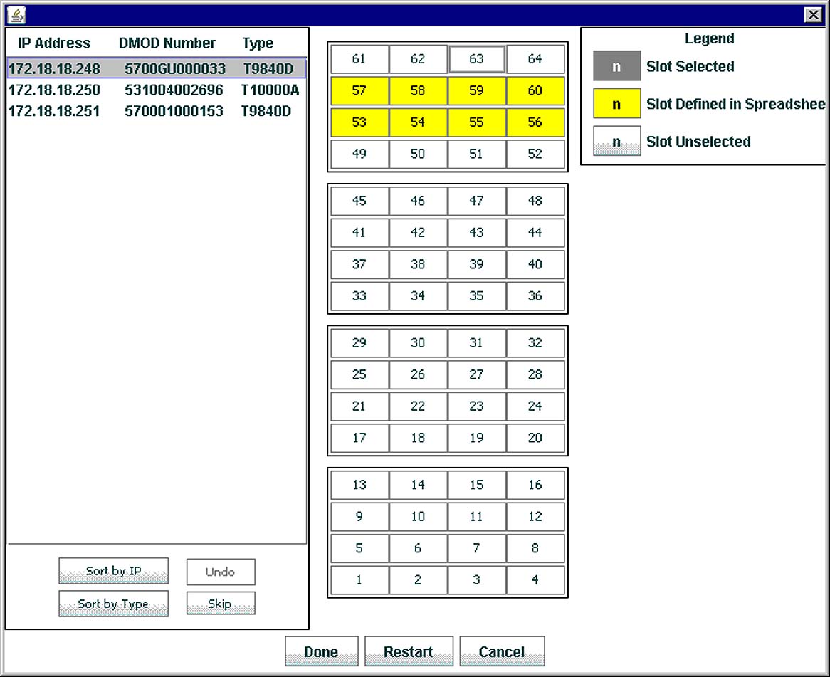
Click the Probe button. MD-VOP scans the library and then the following screen appears:
As shown in Figure 8-5, detected tape drives are listed on the left. Library slots are shown on the right.
You can use the following buttons to sort the list of detected tape drives:
Sort by IP
Sort the list of tape drives by IP address.
Sort by Type
Sort the list of tape drives by drive type.
Undo
Undo the last tape drive placement operation, returning the tape drive to the list of detected tape drives.
Skip
Skip the tape drive at the top of the detected drives list.
Click a slot to assign the first tape drive to the library.
Repeat Step 6 for the remaining tape drives in the list.
When you are finished, click Done. Otherwise, click Restart to clear your changes, or click Cancel to exit the operation.
When you click Done, the drive information is added to the drive definition spreadsheet.
To perform the probe:
Click Library Probe Operations and select Probe IP Range for Drives. The Probe for Drive Location dialog box appears.
Click the radio button for Place by Drive Location (SL3000 and SL8500).
In the Initial Tape Drive IP Address field, enter the starting IP address.
In the IP Range Count field, specify an IP Range Count or click the Rest of Subnet button to automatically change the IP count to extend to the last IP address in the subnet.
Click the Probe button. A progress window appears as MD-VOP begins to probe each IP address in the specified range to locate any tape drives. If you wish to cancel this operation, click the Abort Probe button at any time.
When the probe completes, an informational window appears, indicating the number of tape drives that were located and placed and the number of tape drives that were unable to be placed. You have the option to manually enter the unsuccessful tape drives.
Click OK.
To perform the probe:
Click Library Probe Operations and select Probe IP Range for Drives. The Probe for Drive Location dialog box appears.
Click the radio button for Sequential IP Drive Placement.
In the Initial Tape Drive IP Address field, enter the starting IP address.
In the IP Range Count field, specify an IP Range Count or click the Rest of Subnet button to automatically change the IP count to extend to the last IP address in the subnet.
Click the radio button for Sequential IP Drive Placement.
In the First Library Slot to Use field, enter the library slot number where counting is to begin.
Click the Probe button. A progress window appears as MD-VOP begins to probe each IP address in the specified range to locate any tape drives. Sequential IP addresses are placed starting at the slot you specified in Step 6. If you wish to cancel this operation, click the Abort Probe button at any time.
When the probe completes, an informational window appears, indicating the number of tape drives that were located and placed and the number of tape drives that were unable to be placed. You have the option to manually enter the unsuccessful tape drives.
Click OK.
From the MD-VOP Dashboard, click the File menu and select MDVOP Server to display the MDVOP Server menu. This menu includes the following options:
Use this option to connect MDVOP to an MDVOP server.
From the MDVOP Server menu, select Connect to Server.
A Server Name dialog appears.
Enter the IP address for the MDVOP server and click OK.
MDVOP connects to the server.
Use this option to create a new client configuration from an existing configuration on the MDVOP server.
From the MDVOP Server menu, select Create Client Configuration File from Server.
A Server Name dialog appears.
Enter the IP address for the MDVOP server from which you will select an existing configuration file.
A Remote File Chooser dialog appears, listing all available configuration files.
Select the desired configuration file and click OK.
The configuration file opens and you can save it as a new configuration file.
Use this option to edit a client configuration file on the MDVOP server.
From the MDVOP Server menu, select Edit Client Configuration File on Server.
A Remote File Chooser dialog appears, listing all available configuration files.
Select the configuration you want to edit and click OK.
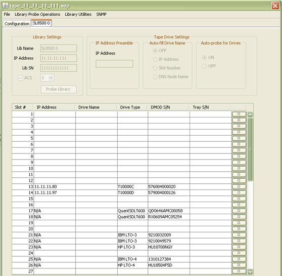
The configuration page for the configuration you selected appears. As shown in Figure 8-6, this window includes a Configuration tab along with separate tabs for each library.
Do one of the following:
Click the Configuration tab to display the configuration page. You can click the Delete library button to delete a library.
Click a library tab to display the library page, listing all drives included in the library. You can click the "X" (delete) button next to a drive to delete it.
When you are finished with your edits, click the File menu and select Save to save the configuration. All changes are saved on the server side, as well as locally.
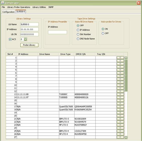
Use this option to edit the domain configuration file (domain.vop), located on the server. This file defines which devices are monitored by the server. Only the services on the server use this file. The client uses a copy of this file called a client configuration.
From the MDVOP Server menu, select Edit Domain Configuration File on Server.
The domain.vop configuration page appears. As shown in Figure 8-7, this page includes a Configuration tab along with separate tabs for each library and VSM.
Do one of the following:
Click the Configuration tab to display the configuration page. You can use this page to add or delete a library. Click the appropriate button.
Click a library tab to display the library page, listing all drives included in the library. You can do the following:.
Edit the library name.
Edit the IP address.
Edit the serial number.
Edit the ACS setting.
Delete a drive. Click the "X" (delete) button next to a drive to delete it.
Click the SNMP option to display the SNMP Configuration screen. Use this screen to enable SNMP for the selected library. This is required for ASR support, to allow communication from the device to the VOP server.
Select Enable SNMP for this library and click OK. The server will begin listening for these libraries.
Click Advanced Settings for troubleshooting options.
Click a VSM tab to display the VSM page, used to discover the VSM.
Enter a VSM name and IP address and click Discover. Once the VSM is discovered, the VSM Information fields are automatically populated
When you are finished with your edits, click the File menu and select Save to save the configuration.
Restart server services.
Use this option to delete a client configuration file on the server.
From the MDVOP Server menu, select Delete Client Configuration File on Server.
A File Chooser dialog appears, listing all client configuration files.
Select the configuration file you want to delete and click OK.
The configuration is deleted.
From the MD-VOP Dashboard, click the File menu and select Default Settings to access the Default Settings screen. Use this screen to change the default MD-VOP display settings.
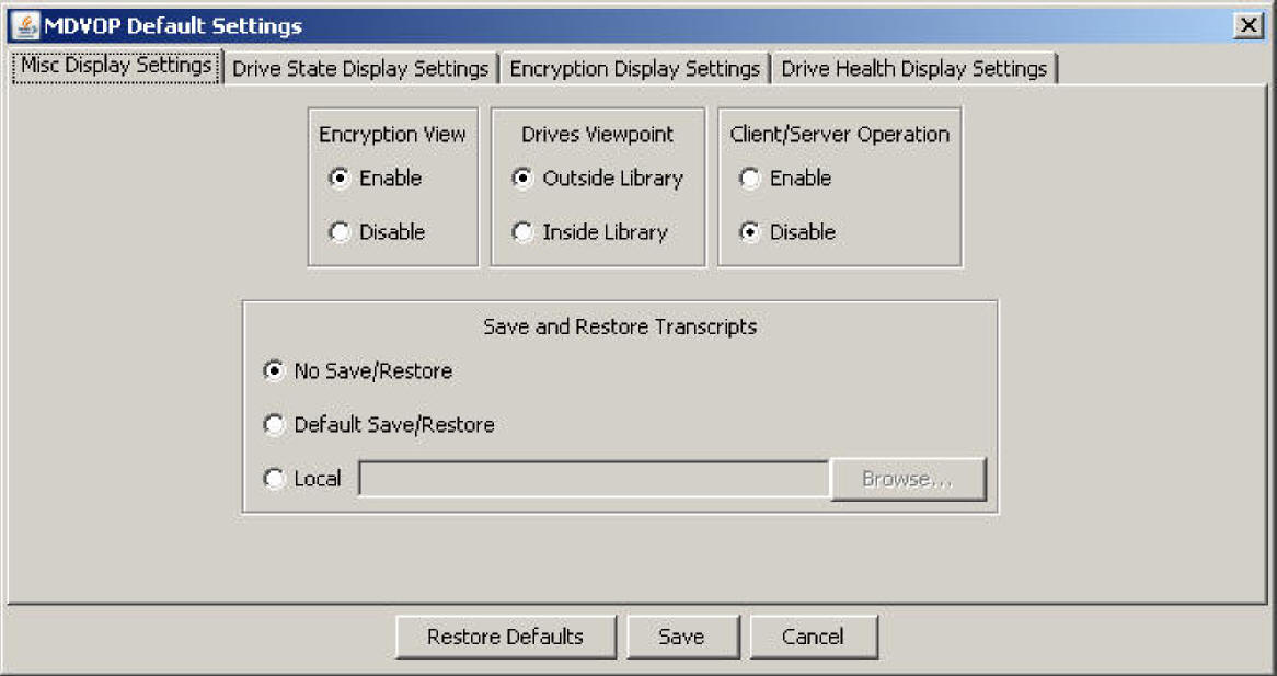
Figure 8-8 shows the MD-VOP Default Settings screen:
As shown in Figure 8-8, this screen includes the following tabs:
Use these tabs to customize your MD-VOP display options. Click a tab to make it active.
Additionally, this screen includes the following buttons:
Restore Defaults
Restores default settings.
Save
Saves current settings.
Cancel
Cancels the operation.
|
Note: These buttons apply to all tabs. |
Click this tab to view or edit general display settings.
As shown in Figure 8-8. This tab includes the following settings:
Encryption View
Click radio buttons to enable or disable the Encryption tab and Encryption menu items in the MD-VOP main interface.
Drives Viewpoint
Click radio buttons to specify whether the library view displays tape drives as if viewing from the front (inside) or back (outside) of the library.
Save and Restore Transcripts
Click one of the following radio buttons to specify transcript settings:
No Save/Restore
Do not save transcripts. This is the default.
Default Save/Restore
Save transcripts in user directory /.mdvop/transcript.
Local
Specify a new location where transcripts are saved.
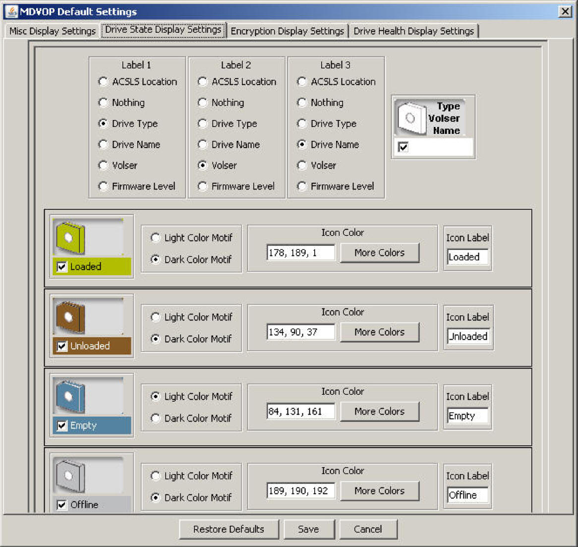
Click this tab to view or edit drive state display settings.
As shown in Figure 8-9, the Drive State Display Settings tab includes the following:
In MD-VOP, each tape drive icon includes three label fields that can display different drive attributes.
For each label (1-3), click one of the following radio buttons to define the attribute to be displayed on the icon:
ACSLS Location
Display the location in ACSLS
Nothing
Display nothing.
Drive Type
Display the drive type.
Drive Name
Display the drive name assigned on the Configuration screen.
Volser
Display the volume serial number if a standard label tape cartridge is loaded.
Firmware Level
Displays the firmware in the tape drive.
Additionally, this tab allows you to change the color setting and icon label for each drive state icon:
Drive state display
For each drive state, click the check box in the icon to show or hide the default display for that drive state.
Color motif
Click the radio buttons to select a light or dark color motif.
Icon color
Enter an RGB value in the dialog box, or click more colors to choose from a palette.
Icon label
Enter label text in the dialog box. This text is displayed beneath the icon in the Library Panel legend.
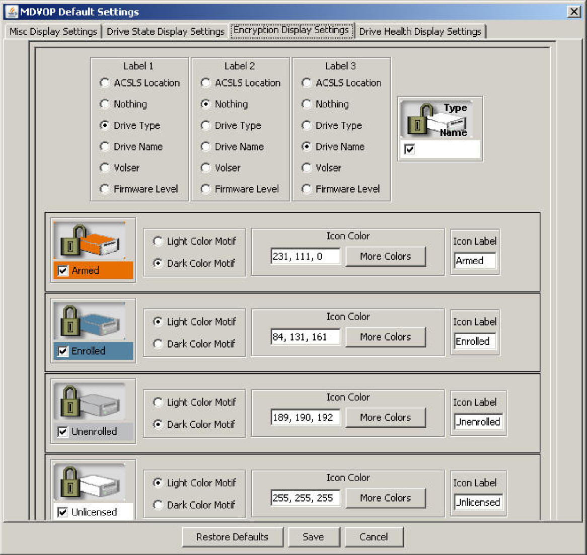
Click this tab to view or edit encryption display settings.
This tab shares the same options as the Drive State tab. See "Drive State Display Settings".
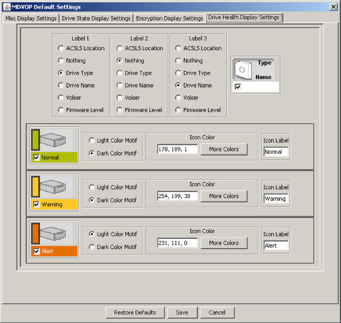
Click this tab to view or edit encryption display settings.
This tab shares the same options as the Drive State tab. See "Drive State Display Settings".
|
 Copyright © 2014, Oracle and/or its affiliates. All rights reserved. Legal Notices |
|