| Oracle Virtual Operator Panel User's Guide Release 2.1 E48640-01 |
|


 Previous |
 Next |
This chapter describes how to use the MD-VOP interface.
Designed for ease of use, the MD-VOP Graphical User Interface (GUI) allows you to do the following:
Navigate through multiple account configurations, including libraries and tape drives.
Monitor, configure, and diagnose Oracle StorageTek tape drives.
View the current state of all tape drives in order to monitor problems as they occur.
Perform mass functions for multiple tape drives, including firmware updates, obtaining logs and dumps, and encryption.
Create My Oracle Service (MOS) issues using the Auto Service Request (ASR) feature.
Connect a VOP client to the VOP server.
Configure the VOP server to enable automated alerts for selective products.
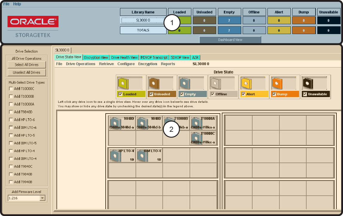
Figure 7-1 shows the MD-VOP main interface:
Legend:
1. Dashboard
2. Library Panel
As shown in Figure 7-1, The MD-VOP interface is divided into two sections:
The Dashboard displays the general state of all tape drives in your configuration.
The Library Panel displays information for tape drives in a selected library.
Both sections include menus you can use to perform various functions on selected tape drives.
The Dashboard displays the general state of all tape drives in your configuration. It displays the number of tape drives in each drive state, for both a selected library and the entire MD-VOP configuration.
|
Note: A tape drive can be in multiple states at a given time. |
The dashboard includes menus you can use to create, launch, and save configurations, and perform other configuration tasks.
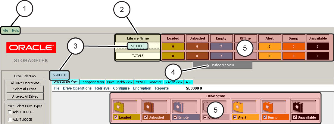
Figure 7-2 shows the MD-VOP dashboard:
Legend:
1. Menus
2. Title
3. Library Name
4. View button
5. Drive State Counts
As shown in Figure 7-2, the Dashboard includes the following:
Menus
Use menus to create, update, or launch an MD-VOP configuration. See Chapter 8, "Using MD-VOP Dashboard Menus" for more information.
Title
The configuration name as defined on the MD-VOP Configuration screen.
Library Name
The library name that was created when the configuration was built. When you click a library name in the dashboard, the corresponding library tab is actively displayed in the library panel.
View Button
Click this button to toggle between the Dashboard view and Full view. In the Dashboard view, the Library Panel is hidden.
Drive State Counts
Displays the number of tape drives in each of the following drive states:
Loaded
Unloaded
Empty
Offline
Alert
Dump
Unavailable
Separate counts are displayed for the selected library, and for all tape drives in the MD-VOP configuration.
|
Note: A tape drive may be in multiple states at a given time. |
See "Drive States" for a description of these drive states.
The Library Panel displays information for tape drives in a selected library. It includes menus you can use to control, update, and view selected tape drives within the library.
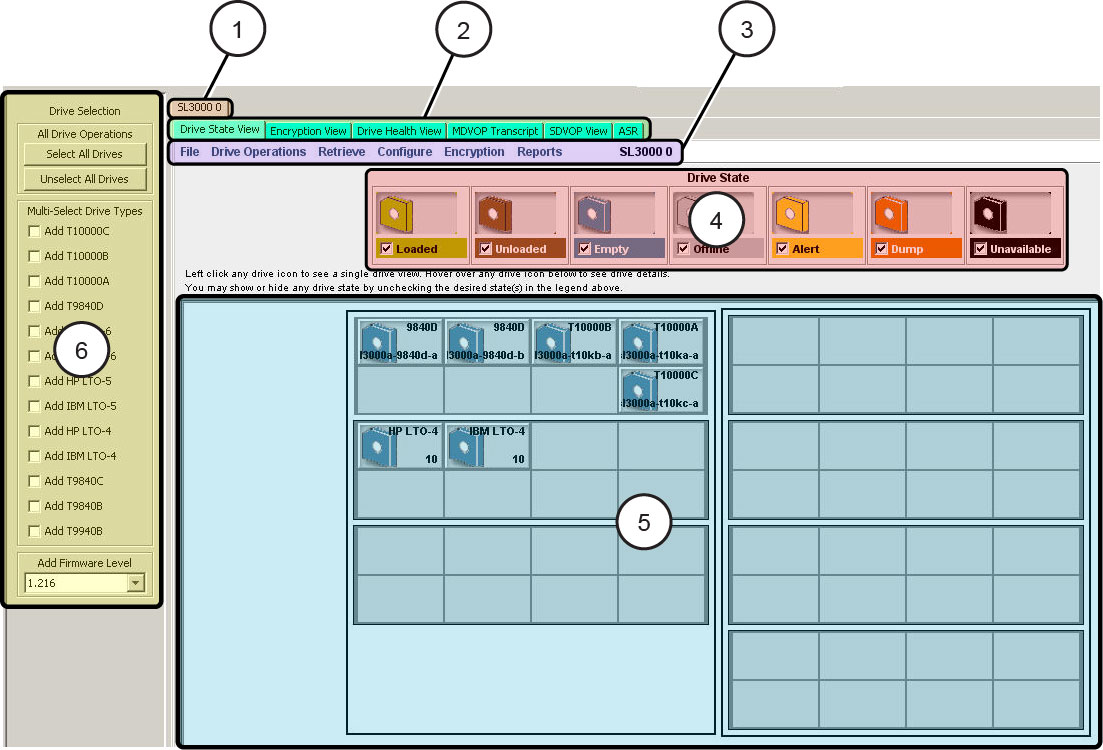
Figure 7-3 shows the MD-VOP Library Panel:
Legend:
1. Library tabs
2. Drive View tabs
3. Menus
4. Legend
5. Drive Details
6. Drive Selection Panel
As shown in Figure 7-3, the Library Panel includes the following:
Library Tabs
These tabs display library names. A separate tab is created for each library in your configuration.
When you click a library tab, it becomes active, and the Library Panel displays tape drive information specific to that library.
Drive View Tabs
These tabs display different types of tape drive information for the tape drives in the selected library.
When you click a tab, it becomes active, and the legend and Drive Details section display accordingly. See "Drive States" for information about each drive state.
Menus
Use menu commands to manipulate or obtain data for one or more selected tape drives. See Chapter 9, "Using MD-VOP Library Panel Menus" for more information.
|
Note: If the SDVOP View tab is selected, these menus change to provide commands specific to the selected tape drive. |
Legend
The legend provides a visual key for the information displayed in the Drive Details section of the Library Panel. The legend is based on the Drive View tab that is active.
Drive Details
The Drive Details section displays an icon for each tape drive in the selected library. These icons are color coded according to the legend.
You can perform the following functions:
Click an individual tape drive icon to display the Single Drive Virtual Operator Panel (SDVOP) View for that tape drive. See "SDVOP View" for information.
Ctrl-click a tape drive icon to select or unselect the tape drive. Once you select a tape drive, you can issue Library Panel menu commands for that drive.
Right-click a tape drive icon to display functions that can be performed on that tape drive.
These are the same functions provided in the Library Panel's Drive Operations menu. See "Drive Operations Menu" for a description of these functions.
Mouse-over a tape drive icon to display the following information for that drive:
Drive state
ONLINE or OFFLINE.
Cartridge
LOADED or EJECTED.
Dump
AVAILABLE or NOT AVAILABLE.
Drive Name
The tape drive name as defined in the MD-VOP Configuration screen.
Volser
The volume serial number of a tape, if present and detected in the tape drive.
Serial Number
The internal serial number of the tape drive.
Firmware Level
The firmware currently loaded on the tape drive.
Port A WWN
The World Wide Name for port A.
Port B WWN
The World Wide Name for port B.
IP Address
The IP address defined for the tape drive.
Host Name
The host name, if detected from DNS.
Library Slot Location
The physical slot location in the library.
Library Internal Location
The physical location in the library as defined internally to the library (SL8500 and SL3000 only).
ACSLS/HLI Address
The location that would appear in the ACS (SL8500 and SL3000 only).
Tray SN
The serial number entered on the MD-VOP Configuration screen, used for support.
Licensed
true or false, to indicate whether the tape drive is licensed for encryption.
Encryption Type
The type of encryption used on this tape drive.
Encryption State
Enrolled or Unenrolled, to indicate whether the tape drive can obtain keys from OKM.
Agent ID
The OKM agent id.
KMS IP
The OKM IP address.
Drive Selection Panel
Use the Drive Selection Panel to select multiple tape drives based on different criteria. This panel applies only to the library that is currently selected.
You can perform the following functions:
Click the Select All Drives button to select all tape drives in the library.
Click the Unselect All Drives button to unselect all tape drives in the library.
Click the Multi-Select Drive Types check boxes to select specific drive types.
Click the Add Firmware Level drop-down menu to select a specific level of tape drive firmware.
|
Note: This can help you identify tape drives that are not at the appropriate firmware level. |
The MD-VOP Library Panel includes the following drive view tabs, used to display different types of information for tape drives in a selected library:
|
Note: By default, the Encryption view is not displayed, unless you indicated to include it when you installed MD-VOP. You can activate this view using the MD-VOP Default Settings screen. See "Changing MD-VOP Default Settings" for more information. |
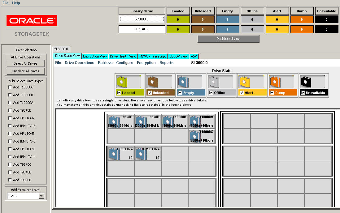
From the MD-VOP Library Panel, select the Drive State View tab to display the current state of the tape drives in the selected library. You may encounter a minimal delay when this view is selected.
This view is only supported for the T9840D, T10000 series, and LTO 4/5 tape drives. All other drives will display a white icon as an indicator of connection, for which other logs can be obtained.
Figure 7-4 shows an example of the Drive State view:
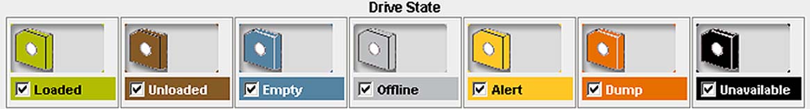
Figure 7-5 shows the legend displayed in the Drive State View:
You can use the legend to filter the tape drives that are displayed in the Library Panel. Click the check box for a particular drive state to include or exclude applicable drives in the Library Panel.
By default, the legend includes the following drive states:
|
Note: You can customize icon labels and colors. See "Changing MD-VOP Default Settings" for more information. |
Loaded
A tape cartridge is loaded and is ready to be used by the tape drive. This status is green by default.
Unloaded
A tape cartridge is unloaded. The tape cartridge resides in the tape drive, but is not actually threaded through the tape drive. This status is brown by default.
Empty
There is no tape cartridge in the tape drive. This status is blue by default.
Offline
The tape drive is not communicating with the system. This state is used for maintenance to the tape drive. In this state, commands from the host (backup server) are not processed. This status is grey by default.
Alert
The tape drive is in need of cleaning due to periodic or error detection limits. This status is yellow by default.
Dump
A dump can occur for a problem that falls outside of the limits in the firmware on the tape drive. This is an SNO (should not occur) in a memory dump from the tape drive. Send the dump to Support for analysis. This status is orange by default.
Unavailable
A tape drive is not communicating with MD-VOP. This status is black by default.
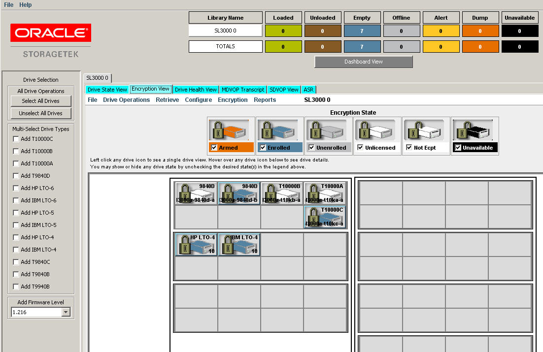
From the MD-VOP Library Panel, click the Encryption View tab to display the current encryption state of the tape drives in the selected library. You may encounter a minimal delay when this view is selected.
|
Note: By default, the Encryption view is not displayed, unless you indicated to include it when you installed MD-VOP. You can activate this view using the MD-VOP Default Settings screen. See "Changing MD-VOP Default Settings" for more information. |
Only T9840D, T10000 series, and encrypting LTO tape drives support encryption through an Oracle Key Manager (OKM) system.
Figure 7-6 shows an example of the Encryption view:
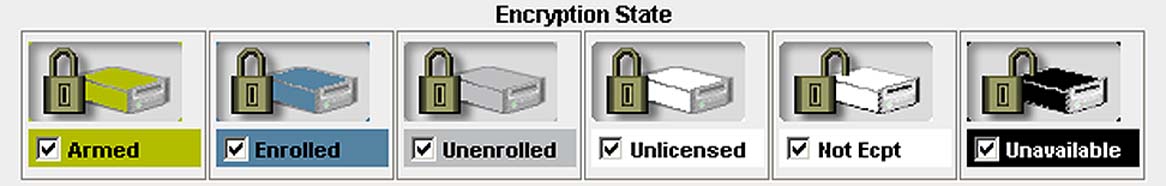
Figure 7-7 shows the legend displayed in the Encryption View:
You can use the legend to filter the tape drives that are displayed in the Library Panel. Click the check box for a particular drive state to include or exclude applicable tape drives in the Library Panel.
By default, the legend includes the following encryption states:
|
Note: You can customize icon labels and colors. See "Changing MD-VOP Default Settings" for more information. |
Armed
The tape drive has acquired an encryption key from OKM. The tape drive can write encrypted data. This status is green by default.
Enrolled
The tape drive is enrolled with OKM but does not have an encryption key from OKM. This status is blue by default.
Unenrolled
The tape drive has been reset and is no longer enrolled with OKM. The tape drive cannot write encrypted data. This status is gray by default.
Unlicensed
The tape drive is capable of encryption, but the license key for the tape drive has not been sent to the tape drive. This status is white by default.
Not ecpt
The tape drive is not capable of encryption. This status is white by default.
Unavailable
The tape drive is not communicating with MD-VOP. This status is black by default.
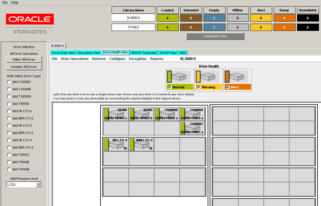
From the MD-VOP Library Panel, click the Drive Health View tab to display the current health status of the tape drives within the selected library. You may encounter a minimal delay when this view is selected.
|
Note: At MD-VOP startup, the ”good” state color is indicated by default. This remains until you issue a Perform Health Check command from the Library Panel Drive Operations menu. See "Drive Operations Menu" for more information. |
Figure 7-8 shows an example of the Drive Health view:
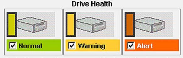
Figure 7-9 shows the legend displayed in the Drive Health view:
You can use the legend to filter the tape drives that are displayed in the Library Panel. click the check box for a particular drive state to include or exclude applicable tape drives in the Library Panel.
By default, the legend includes the following drive health states:
|
Note: You can customize icon labels and colors. See "Changing MD-VOP Default Settings" for more information. |
Normal
No events are found on the tape drive. This status is green by default.
Warning
The tape drive has a concern that requires review. This status is yellow by default.
Alert
The tape drive requires attention. This status is also triggered when the tape drive is unavailable for connection. This status is red by default.
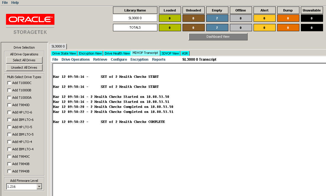
From the MD-VOP Library Panel, click the MD-VOP Transcript tab to display all global commands sent or received from the tape drives in the selected library.
|
Note: You may encounter a minimal delay when this view is selected. |
MD-VOP transcripts are stored in the transcripts subdirectory within the MD-VOP application folder. Figure 7-10 shows an example of the MD-VOP Transcript view:
Click a tape drive icon in the Library Panel to access the SDVOP (single-drive) View for that tape drive. The SDVOP View tab becomes active.
If you click a T9840D or T10000 tape drive, the T10000 9840D SDVOP interface is displayed in the MD-VOP Library Panel. See Chapter 10, "Using T10000 9840D VOP" for information about using T10000 9840 VOP.
If you click an LTO tape drive, the LTO VOP interface is displayed in the MD-VOP Library Panel. See Chapter 11, "Using LTO VOP" for information about using LTO VOP.
If you click a T9840B, T9840C, T9940A, or T9940B tape drive, the 9XXX VOP interface is displayed in the MD-VOP Library Panel. See Chapter 12, "Using 9XXX VOP" for information about using 9XXX VOP.
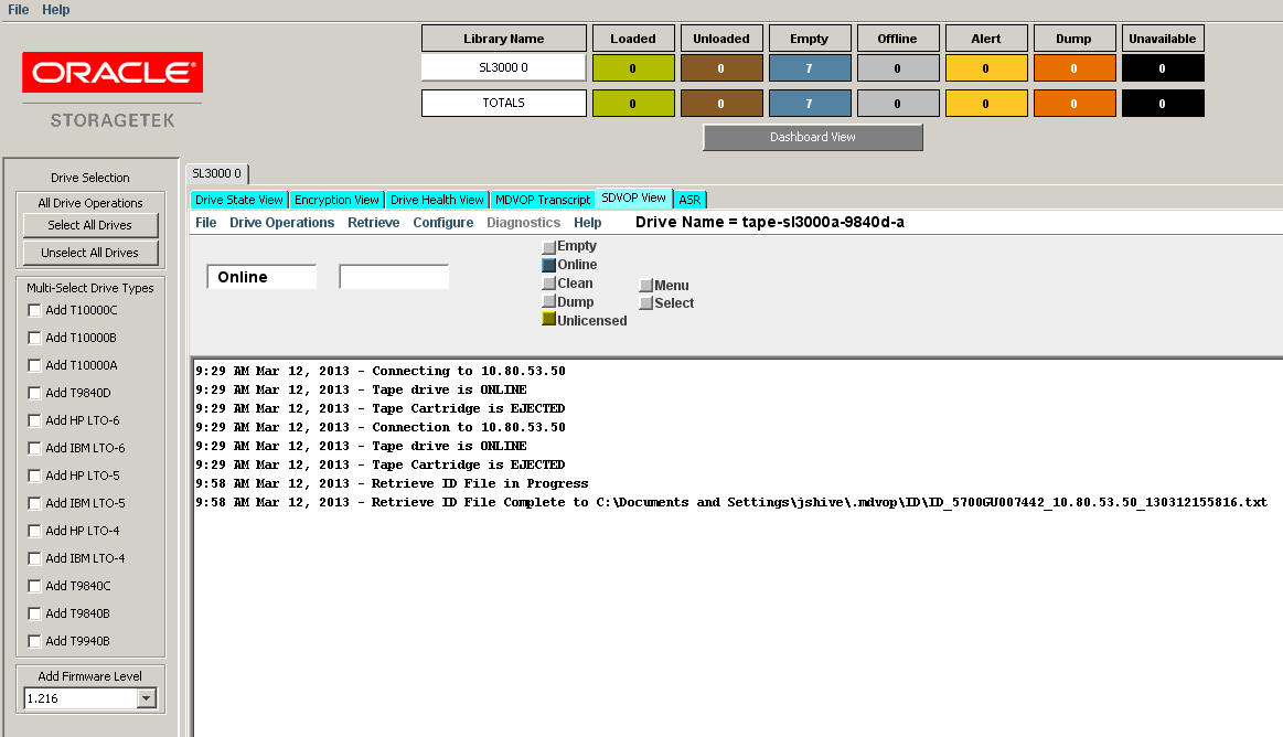
Figure 7-11 shows an example of the SDVOP view for a T10000 tape drive:
As shown in Figure 7-11, the SDVOP View is active, and the T10000 9840D VOP interface is displayed in the MD-VOP Library Panel.
From the MD-VOP Library Panel, click the ASR tab to display the ASR view.
|
Note: You may encounter a minimal delay when this view is selected. |
Auto Service Request (ASR) is a feature of Oracle Premier Support for Systems and Oracle Limited Warranty that is designed to automatically request Oracle service when specific hardware faults occur.
ASR is designed to resolve problems more quickly by eliminating the need to initiate contact with Oracle services for hardware failures, reducing both the number of phone calls needed and overall phone time required. ASR also simplifies support operations by utilizing electronic diagnostic data. ASR is easy to install and deploy is completely controlled by you to ensure security.
For more information about ASR, refer to the ASR publications available at the following URL:
Under the client/standalone VOP:
Register the application. See "ASR Register".
Configure one or more devices to VOP and enter serial numbers where appropriate.
Activate the assets. See "ASR Activate".
Access My Oracle Support (MOS) and confirm that the assets are activated.
For more information, visit the following URL:
http://www.oracle.com/technetwork/systems/asr/documentation/index.html
Optionally, send a test message or simulate an event.
To enable the automatic ASR feature included in the VOP server:
For libraries, click the SNMP button on the Domain Configuration page. See "Edit Domain Configuration File on Server".
For VSM, click the Domain Configuration page. This automatically configures the VSM and server. See "Edit Domain Configuration File on Server".
For T10000 tape drives:
Access the MDVOP single drive view for the drive and place the drive offline. See "SDVOP View".
Access the data from the drive and select the SNMP tab.
Enter the IP address for the server and select Save. The drive reboots.
For a 9xxx tape drive, place a file on the system.
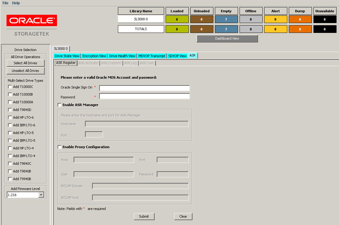
Figure 7-12 shows an example of the MD-VOP ASR view:
As shown in Figure 7-12, the ASR view includes the following tabs:
By default, the ASR Activate page is selected when you click the ASR tab.
Before you can create a service request, you must first register with MOS (using the ASR Register tab) and activate your devices (using ASR Activate tab).
To use the ASR feature, you must first register with My Oracle Support (MOS) and optionally, the ASR Manager.
If you are connecting to ASR Manager, you must perform registration in ASR Manager before using the ASR Register page in MD-VOP.
The ASR backend infrastructure at Oracle collects all telemetry data forwarded to it from the ASR Manager. The fault-rule technology on these backend systems ascertains the reality of the fault telemetry, and forwards recognized faults to Oracle's Service Request system. From there, the following actions occur:
A Service Request, also called a case, is created and assigned to an Oracle Support Engineer. At the same time, an e-mail notification of the Service Request is sent to your support contact on record associated with the system reporting a fault.
The Service Request is handled in accordance with the asset's Support or Warranty contract.
To register:
In the Enter valid Oracle MOS account field, enter your My Oracle Support (MOS) username and password.
Enter ASR Manager internet settings. The ASR Manager is a system that centrally accepts hardware telemetry data sent from a group of ASR Assets. The ASR Manager filters the incoming data and forwards potential fault telemetry to Oracle ASR backend systems.
If you are accessing the ASR Manager directly, click the ASR Manager check box and then enter the ASR Manager Hostname and Port for the server where ASR Manager resides.
If you are accessing the internet through a proxy, click the Enable Proxy Configuration check box and provide the following:
Proxy server host name
Proxy port number
Proxy user name
Proxy password
NTLM Domain Name (if applicable)
NTLM Host Name (if applicable)
|
Note: If you access the internet through a proxy, check with your network administrator to collect information needed to configure the ASR Manager system. |
Click the Submit button to register with the supplied information, or click the Clear button to cancel the operation.
Click this tab to display the ASR Activate page. Use this page to activate one or more tape drives. In order to create an ASR for a particular tape drive, you must first activate the tape drive. By default, libraries are automatically added to the activate list.
To activate a tape drive, select it from the Available Devices window and drag and drop it in the Selected/Activated Devices window.
Devices are listed with the following information:
drive type
internal serial number
tray serial number
entitled status
|
Note: An asterisk indicates a device that has already been activated. |
After you activate one or more tape drives, the Account Manager must enable these ASR Assets in My Oracle Support. Otherwise, any alerts you attempt to send will be dropped. Refer to the Oracle Auto Service Request Installation and Operations Guide for instructions. A valid service contract is required.
Click this tab to display the ASR Creation page. Use this page to create a MOS Service Request, or Case, for one or more tape drives.
|
Note: Before you can create a service request, you must first register with MOS (using the ASR Register tab) and activate your devices (using the ASR Activate tab). |
To create a Service Request:
Click the drop-down menu and select an activated tape drive for which to create a MOS Service Request.
Select additional devices for the Service Request. Drag and drop devices from the Available Devices window to the Selected drives window.
Enter any additional information to be included in the Service Request.
Click the Create ASR button to create the Service Request in MOS, or click the Clear button to cancel the operation.
Once the Service Request is created in MOS, logs are automatically collected, transmitted to the Oracle ASR backend system, and attached to the Service Request.
Click this tab to test end-to-end communications between a tape drive and the Oracle ASR backend system.
|
Note: Before you can test communications, you must first register with MOS (ASR Register tab) and activate your devices (ASR Activate tab). |
To test communications:
Click the drop-down menu and select an activated tape drive.
Click the Test button.
When the test completes, the user registered under MOS receives a confirmation e-mail indicating whether the test was successful. If the test fails, the e-mail includes possible causes.
|
 Copyright © 2014, Oracle and/or its affiliates. All rights reserved. Legal Notices |
|