4 Workflow
A Data Miner workflow is a mechanism to define data mining operations such as model build, test, and apply. These operations are defined in nodes, which comprise the workflow. You can create multiple workflows in a single project. This chapter provides the following information:
4.1 About Workflows
A workflow must contain one or more sources of data, such as a table or a model. For example, to build a Naive Bayes model, you must first identify the input with a Data Source node. Then you create a Classification Node to build and test the model.
Using a workflow, you can:
-
Build, analyze, and test data mining process
-
Identify and examine data sources
-
Build and apply models
-
Create predictive queries
This section contains of following topics:
4.1.1 Workflow Sequence
A workflow is built and run in the following sequence:
-
Create a blank workflow.
-
Add nodes to the workflow.
-
Connect the nodes in a workflow.
-
Run the nodes.
-
Examine the results.
-
Repeat the steps as required.
4.1.2 Workflow Terminology
A workflow is a directed graph consisting of nodes that are connected to one another. There are specific terms used to indicate the nodes in relation to the workflow.
For example, consider a workflow composed of two nodes, N1 and N2. Assume that N1 is connected to N2:
-
Parent node and child node: The node N1 is the parent node of N2, and the node N2 is a child of N1. A parent node provides information that the child node needs when it runs. You must build a model before you apply to new data.
-
Descendants and ancestors: The node N2 is called the descendant of N1 if there is a workflow connection starting from N1 that eventually connects to N2. N1 is called the ancestor of N2. N1 is always closer to the root node than N2.
-
Root nodes: The nodes that have no parent nodes are called root nodes. All workflows have at least one root node. A parent node can have multiple root nodes.
Note:
A parent node is closer to a root node than its child node. -
Siblings: If a node has several child nodes, then the child nodes are referred to as siblings.
-
Upstream: Parent nodes are called upstream of child nodes.
4.1.3 Workflow Thumbnail
The thumbnail view of the workflow provides an overall view of the workflow. Thumbnails are most useful for large workflows.
To open the Thumbnail viewer, go to View and click Thumbnail. Alternately, press Ctrl+Shift+T to open the Thumbnail viewer.
In a Thumbnail view, you can:
-
Navigate to a specific node in the workflow
-
Change the zoom level of the workflow
-
Change the node that is currently viewed in the workflow
Description of the illustration thumbnail.gif
The Thumbnail view includes a rectangle. Click inside the viewer to move the rectangle around, thereby changing the focus of the display in the workflow editor. You can also resize the rectangle for a finer level of control.
When viewing models in the Thumbnail view, if the model generates trees, then the Thumbnail view automatically opens to provide an overall view to display the shape of the tree. The Thumbnail view also shows your location in the overall model view.
4.1.4 Components
The Components pane lists the components that you can add to workflows. To add a component to a workflow, drag and drop the component from the Components pane to the workflow.
The Components pane opens automatically when you load a workflow. If the Components pane is not visible, then go to View and click Components.
The Components pane includes the following:
4.1.4.1 My Components
My Components has two tabs:
-
Favorites: To add a component to the Favorites list, right-click the component and select Add to Favorites.
-
Recently Used: Lists recently used components.
4.1.4.2 Workflow Editor
The Workflow Editor contains nodes that are categorized into sections. You can create and connect the following nodes in a workflow:
4.1.4.3 All Pages
All Pages lists all available components in one list.
4.1.5 Workflow Properties
The Workflow Properties tab enables you to add or change comments associated with the selected workflow.
See Also:
"Properties" for an overview of the Properties functionality.4.1.6 Properties
Properties enables you to view and change information about the entire workflow or a node in a workflow.
Note:
In the earlier releases of Oracle Data Miner, the Properties tab was known as the Property Inspector.To view the properties of a node, right-click the node and select Go to Properties.
If you select either the workflow or one of its node, the respective properties are displayed in the Properties pane. For example, if you select a Data Source node, the Data Source node properties are displayed in the Properties pane.
You can perform multiple tasks for a node and a workflow from:
-
Properties context menu:
-
Properties pane:
4.2 Working with Workflows
You can perform the following tasks with a workflow. However, you must ensure that the Workflow Prerequisites are met.
4.2.1 Workflow Prerequisites
Before you can perform any task with a workflow, ensure that the following workflow prerequisites are met:
-
Create and establish a connection to the database.
-
Create a Project under which the workflow is created.
See Also:
4.2.2 Creating a Workflow
Before you create a workflow, ensure that you meet the workflow prerequisite conditions.
To create a blank workflow:
-
In the Data Miner tab, expand Connections in the left pane.
If the Data Miner tab is not open, then click Tools and select Data Miner.
-
Select the project under which you want to create the workflow.
-
Right-click the project and select New Workflow from the context menu. The Create Workflow dialog box opens.
-
In the Name field, enter a unique name for the workflow.
-
Click OK. This creates a blank workflow.
4.2.3 Deleting a Workflow
To delete a workflow:
-
In the Data Miner tab, expand Projects and select the workflow that you want to delete.
-
Right-click and click Delete.
4.2.4 Renaming a Workflow
To change the name of a workflow or project:
-
Right-click the name of the workflow or project in the Data Miner tab and select Rename.
-
The Rename Workflow dialog box or Rename Project dialog box opens. Enter the new name in the Rename To field.
For a project, the new name must satisfy the project name restrictions. For a workflow the new name must satisfy the workflow name restrictions.
-
Click OK.
4.2.5 Loading a Workflow
After creating a workflow, you can perform the following tasks:
-
Load a workflow: In the Data Miner tab, expand the project and double-click the workflow name. The workflow opens in a new tab.
-
Close a workflow: Close the tab in which the workflow is loaded and displayed.
-
Save a workflow: Go to File and click Save. If a workflow has any changes, they are saved when you exit.
4.2.6 Managing a Workflow
After you create a workflow, the workflow is listed under Projects in the Data Miner tab.
To perform any one of the following tasks, right-click the workflow under Projects and select an option from the context menu:
-
New Workflow: To create a new workflow in the current project.
-
Delete: To delete the workflow from the project.
-
Rename: To rename the workflow.
-
Export: To export a workflow.
-
Import: To import a workflow.
4.2.6.1 Exporting a Workflow Using the GUI
To export a workflow:
-
In the Data Miner tab, expand Connection and click the project under which the workflow is created.
-
Right-click the workflow that you want to export and click Export. The Save dialog box opens.
-
In the Save dialog box, navigate to the location where you want to export the workflow and click Save. The workflow is saved as an XML file.
Note:
The default directory to save the workflow is the system default directory for saving documents. You can change this directory.
4.2.6.2 Importing a Workflow Using the GUI
You can import workflows into a project. Before you import a workflow, ensure that the import requirements of a workflow are met.
To import a workflow:
-
In the Data Miner tab, right-click the project where you want to import the workflow and click Import Workflow. The Open dialog box opens.
-
In the Open dialog box, navigate to the location where the workflow XML file is.
-
Click Open. The system verifies that the specified file contains a workflow and determines the version number of the workflow. The Import Workflow dialog box opens. You can select and import only one workflow at a time.
-
In the Import Workflow dialog box, specify a name for the new workflow and select any one of the following options to handle naming conflicts:
-
Rename Model and Output Table name if necessary
-
Keep Existing Model and Output Table name even if conflict exists
-
See Also:
"Import Requirements of a Workflow"4.2.6.2.1 Import Workflow
The Import Workflow dialog box enables you to specify the name of the workflow that is imported and how to handle naming conflicts. The default workflow name is the file name of the workflow. It may be necessary to:
-
Change the name slightly to avoid conflicts.
-
Edit the name so that it is a valid workflow name. The name of the new workflow must be unique in the new connection.
You must also select how to handle naming conflicts in names of workflow nodes and output tables. The default is Rename Model and Output Table names if necessary.
You can select Keep Existing Model and Output table names even if conflict exists. If you select this option, you must resolve any conflicts yourself.
To start the import, click OK.
4.2.6.3 Import Requirements of a Workflow
The import requirements of a workflow are:
-
All the tables and views used as data sources in the exported workflow must be in the new account.
-
The tables or views must have the same name in the new account as they did in the old account.
-
It may be necessary to redefine the Data Source node.
-
If the workflow includes Model nodes, then the account where the workflow is imported must contain all models that are used. The Model node may have to be redefined in the same way that Data Source nodes are.
-
You must have permission to run the workflow.
-
The workflow must satisfy the compatibility requirements.
See Also:
4.2.6.4 Data Table Names
The account from which the workflow is exported is encoded in the exported workflow.
Example:
Assume that a workflow is exported from the account DMUSER and contains the Data Source node with data MINING_DATA_BUILD.
If you import the schema into a different account, that is, an account that is not DMUSER, and try to run the workflow, then the Data Source node fails because the workflow looks for DMUSER.MINING_DATA_BUILD_V.
To resolve this issue:
-
Right-click the Data Source node
MINING_DATA_BUILD_Vand select Define Data Wizard.A message appears indicating that
DMUSER.MINING_DATA_BUILD_Vdoes not exist in the available tables or views. -
Click OK and select
MINING_DATA_BUILD_Vin the current account. This resolves the issue.
4.2.6.5 Workflow Compatibility
The compatibility requirements for importing and exporting workflows are:
-
Workflows exported using a version of Oracle Data Miner earlier than Oracle Database 11g Release 2 (11.2.0.1.2) cannot always be imported into a later version of Oracle Data Miner.
-
Workflows exported from an earlier version of Oracle Data Miner may contain invalid XML. If a workflow XML file contains invalid XML, then the import is terminated.
To check the Oracle Data Miner version:
-
Go to Help and click Version.
-
Click the Extensions tab.
-
Select Data Miner.
4.2.6.6 Building and Modifying Workflows
The Workflow Editor is the tool to modify workflows. The Workflow Editor is supported by:
4.2.6.7 Missing Tables or Views
The schema that is imported into a workflow may not have all the tables or views used by the workflow. When Data Miner detects this problem, it generates the Table Selection Failure message indicating that the table is missing. You have the choice to select another table.
To select another table, click Yes. The Define Data Source Wizard opens. Use the wizard to select a table and attributes.
4.2.6.8 Managing Workflows using Workflow Controls
Several controls are available as icon in the top border of a workflow, just below the name of the workflow. You can perform the following tasks:
-
Zoom in and zoom out workflow nodes: Click the
 and
and  icon respectively.
 -
Control node size: Click the percent drop-down list and select the size. Default size is 100%.
-
View event log: Click the
 icon.
icon. -
Run selected nodes: Click the
 icon. When you select the node to be run, the triangle turns green.
 -
Cancel a running workflow: Click the
 icon.
icon.
4.2.6.9 Managing Workflows and Nodes in the Properties Pane
In the Properties pane, you can view and change information about the entire workflow or a node in a workflow. To view the properties for a node:
-
Right-click the node and select Go to Properties. The corresponding Properties pane opens. For example, if you select a Data Source Node, in the Properties pane, the details of the Data Source node is displayed.
-
Use the Search field to find items in Properties.
-
Click the
 icon to open the editor for the item that you are viewing.
 -
Use the options in the context menu to perform additional tasks.
4.2.6.10 Performing Tasks from Workflow Context Menu
To view a workflow, double-click the name of the workflow in the Data Miner tab. The workflow opens in a tab located between the Data Miner tab and the Components pane. If you open several workflows, each workflow opens in a different tab. Only one workflow is active at a time.
To display the workflow context menu, right-click a workflow tab. The following options are available in the context menu:
-
Close: Closes the selected tab.
-
Close All: Closes all workflow tabs.
-
Close Other: Closes all tabs except the current one.
-
Maximize: Maximizes the workflow. The Data Miner tab, Components pane, and other items are not visible. To return to previous size, click the selection again.
-
Minimize: Minimizes the Properties tab to a menu. To return to the previous size, right-click the Properties tab, and click Dock.
-
Split Vertically: Splits the active editor or viewer into two documents. The two documents are split vertically. Click the selection again to undo the split.
-
Split Horizontally: Splits the active editor or viewer into two documents. The two documents are split horizontally. Click the selection again to undo the split.
-
New Document Tab Group: Adds the currently active editor or viewer into its own tab group. Use Collapse Editor Tab Groups to undo this operation.
-
Collapse Document Tab Groups: Collapses all the editors or viewers into one tab group. Only displayed after New Editor Tab Group.
-
Float: Converts the Properties tab into a movable pane.
-
Dock: Sets the location for floating window. Alternately, you can press Alt+Shift+D.
-
Clone: Creates a new instance of Properties.
-
Freeze Content: Freezes the content. To unfreeze Properties, click again on this selection.
4.2.7 Running a Workflow
The View Event Log enables you to view the progress of running of a workflow. You can also view the time taken for workflow creation.
Oracle Data Miner uses Oracle Scheduler to schedule running of workflows. For an overview of Oracle Scheduler, see the Oracle Database Administrator's Guide
Model builds can be very resource-intensive. The MAX_NUM_THREADS parameter in the Oracle Data Miner server controls the number of parallel builds. MAX_NUM_THREADS specifies the maximum number of model builds across all workflows running in the server.
Default Value=10. Therefore, by default, 10 models can occur concurrently across all workflows. There is the MAX_NUM_THREADS parameter in the repository table ODMRSYS. ODMR$REPOSITORY_PROPERTIES, where you can specify the value.
If you increase the value of MAX_NUM_THREADS, do it gradually. Workflows can appear to be running even though the network connection is lost.
To control the parallel model build behavior, the following parameters are used:
-
THREAD_WAIT_TIME. The default is 5. WhenMAX_NUM_THREADSis reached, further Build process will be put on queue until parallel model build count <MAX_NUM_THREADS.This setting (in seconds) determines how often to check for parallel model build count. -
MAX_THREAD_WAIT. The default is NULL. The timeout (in seconds) for Build process that has been put on queue. If NULL, no timeout will occur.
4.2.7.1 Network Connection Interruption
If a network connection to the Data Miner server is interrupted while running a workflow, the Workflow Editor may indicate that the workflow is still running indefinitely. On the other hand, the Workflow Jobs window may indicate that the connection is down.
Data Miner issues a message indicating that the connection was lost. If the connection is not recovered in a reasonable period, close and open the Workflow Editor again.
Note:
Use the Workflow Jobs window to monitor connections.4.2.7.2 Locking and Unlocking Workflows
A workflow is locked under the following conditions:
-
When a node is running, the workflow is locked, and none of its nodes can be edited. Existing results may be viewed while the workflow is running. You can also go to a different workflow and edit or run it.
-
When a user opens a workflow, the workflow is locked so that other users cannot modify it.
-
When a workflow is running, an animation in the tool bar (circular arrow loop) shows that the workflow is running.
-
When you open a locked workflow, Locked is displayed in the tool bar and a running indicator if the workflow is running:

-
If no one else has the workflow locked, and you are given the lock, then lock icon is removed from the tool bar.
-
Unlocking a locked workflow: If a workflow seems to complete, but is still locked, click Locked to unlock the workflow.
-
Refreshing Workflow: Once a locked workflow has stopped running, you can refresh the workflow by clicking the
 icon. You can also try to obtain the lock yourself by clicking on the lock.
4.2.8 Deploying Workflows
Data Miner 4.1 enables you to generate a script from a workflow that recreates all the objects generated by that workflow. In earlier releases of Data Miner, you could only generate a script for Transformation nodes.
A script that recreates all objects generated by that workflow, also enables you to replicate the behavior of the entire workflow. Such scripts provide a basis for application integration or a lightweight deployment of the workflow, that does not require Data Miner repository installation and workflows in the target and production system.
Data Miner 4.1 provides the following two types of deployment:
4.2.8.1 Deploying Workflows using Data Query Scripts
Any node that generates data has the Save SQL option in its context menu.
The Save SQL option generates a SQL script. The generated SQL can be created using the SQL*Plus script or as a standard SQL script. The advantage of the script format is the ability to override table and model references with parameters.
The Save SQL option enables you to select the kind of script to generate, and the location to save the script.
See Also:
Save SQL4.2.8.2 Deploying Workflows using Object Generation Scripts
The Object Generation Script generates scripts that create objects. The scripts that generate objects are:
4.2.8.3 Running Workflow Scripts
You can run the generated scripts in the following ways:
-
As Oracle Enterprise Manager Jobs, either as SQL Script or an operating system command.
-
As Oracle Scheduler Jobs:
-
External Jobs that calls the SQL Script
-
Environment: Using Oracle Enterprise Manager for runtime management or using PL/SQL
-
-
Run the scripts using SQL*PLus or SQL Worksheet. To run a script, ensure that Oracle Data Miner repository is installed.
4.2.9 Workflow Script Requirements
Workflow script requirements include the following specific requirements:
4.2.9.1 Script File Character Set Requirements
Scripts can contain characters based on character sets that will not be handled well unless the script file is generated using UTF8 character set.
Note:
Ensure that all script files are generated using UTF8 character set.4.2.9.2 Script Variable Definitions
The scripts have variable definitions that provide object names for the public objects created by the scripts. The Master Script is responsible for calling all underlying scripts in order. So, the variable definitions must be defined in the Master Script.
The variable Object Types enables you to change the name of the object names that are input to the scripts, such as tables or views, and models. By default, these names are the original table or view, and model names.
All generated scripts should be put under the same directory.
4.2.9.3 Scripts Generated
In this kind of deployment, several general scripts are generated:
-
Master Script: Starts all the required scripts in the appropriate order. The script performs the following:
-
Validates if the version of the script is compatible with the version of the Data Miner repository that is installed.
-
Creates a workflow master table that contains entries for all the underlying objects created by the workflow script.
-
Contains generated documentation covering key usage information necessary to understand operation of scripts.
-
-
Cleanup Script: Drops all objects created by the workflow script. The Cleanup Script drops the following objects:
-
Hidden objects, such as the table generated for Explore Data.
-
Public objects, such as Model Names created by Build Nodes.
-
Tables created by a Create Table Node.
-
-
Workflow Diagram Image: Creates an image (.png file) of the workflow at the time of script generation. The entire workflow is displayed.
The other scripts that are generated depend on the nodes in the chain. Table 4-1 lists the nodes and their corresponding script functionality.
Table 4-1 Nodes and Script Functionality
| Node | Script Functionality |
|---|---|
|
Creates a view reflecting the output of the node. |
|
Filter Column node |
Creates a view reflecting the output of the Filter Column node such as other Transform type nodes. If the |
|
Build Text node |
For each text transformation, the following objects are created:
Creates a view reflecting the output of the Build Text node. This is essentially the same output as an Apply Text node |
|
Classification Build node |
A model is created for each model build specification. A master test result table is generated to store the list of test result tables generated per model. GLM Model Row Diagnostics Table is created if row diagnostics is turned on. Each Model Test has one table generated for each of the following test results: Performance, Performance Matrix, ROC (for binary classification only). Each Model Test has one table for each of the following tests per target value (up to 100 maximum target values): List and Profit. |
|
Regression Build node |
A model is created for each model build specification. GLM Model Row Diagnostics Table is created if row diagnostics is turned on. A master test result table is generated to store the list of test result tables generated per model. Each Model Test will have one table generated for each of the following test results: Performance and Residual. |
|
A model is created for each model build specification. |
|
Test Node (Classification) |
A master test result table is generated to store the list of test result tables generated per model. GLM Model Row Diagnostics Table is created if row diagnostics is turned on. Each Model Test has one table generated for each of these test results: Performance, Performance Matrix, ROC (for binary classification only). Each Model Test has one table for each of Lift and Profit per target value up to 100 maximum target values. |
|
Test Node (Regression) |
GLM Model Row Diagnostics Table is created if row diagnostics is turned on. A master test result table is generated to store the list of test result tables generated per model. Each Model Test has one table generated for each of Performance and Residual. |
|
No scripts are generated. These nodes are just reference nodes to metadata. |
4.2.9.4 Running Scripts using SQL*Plus or SQL Worksheet
If you run generated scripts using either SQL*Plus or SQL Worksheet and require input from users, then use the following command before the generated SQL:
set define off
You can either run this new line separately before running the generated SQL. You can also generate the new line along with the generated SQL.
4.2.10 Oracle Enterprise Manager Jobs
Oracle Enterprise Manager (OEM) allows Database Administrators to define Jobs through the OEM application. The Job is run through OEM instead of Oracle Scheduler. The Job can be run manually from OEM. The running of the job can be monitored. The result is either a success or a reported failure.
-
The Job definitions can directly open the generated scripts files.
-
The Job definition should define the master script invocation as a script file using a full file path.
-
The Job can be run on a schedule or on demand.
-
All script that run within the master script must have fully qualified path names.
For information about Enterprise Manager, see the Oracle Enterprise Manager documentation set, Oracle Database 2 Day DBA, or any of the Oracle Database 2 Day + books for the database to which you are connected.
4.2.11 Runtime Requirements
The generated scripts require access to Data Miner repository objects. The Data Miner repository must be installed on the system where the scripts are run. The script checks the repository version and ensures that the repository is the same version or greater than the version of the source system.
4.3 About Nodes
A workflow consists of one or more nodes that are connected by a link. Nodes define the data mining operations in a workflow. The node categories, listed in Table 4-2, are available in the Components pane.
4.3.1 Node Name and Node Comments
Every node must have a name and may have a comment.
Name assignment is fully validated to assure uniqueness.
Oracle Data Miner generates a default node name. When a new node of particular type is created, its default name is based on the node type, such as Class Build for a Classification node. If a node with that name already exists, then the name is appended with 1 to make it unique. So if Class Build exists, then the node is named Class Build 1. If Class Build 1 exists, then 2 is appended so that the third Classification node is named Class Build 2, and so on. Each node type is handled independently. For example, Filter Columns node have its own sequence, different from the sequence of Classification nodes.
You can change the default name to any name that satisfies the following requirements:
-
Node names must be unique within the workflow.
-
Node names must not contain any / (slash) characters.
-
Node names must be at least one character long. They cannot be 31 or more characters long.
To change a node name, either change it in the Details tab of Properties or select the name in the workflow and type the new name.
Comments for the node are optional. If you provide any comments, it must be not more than 4000 characters long.
4.3.2 Node Types
Table 4-2 lists the different categories of nodes:
| Type | Description |
|---|---|
|
They specify models to build or models to add to a workflow. |
|
|
They evaluate and apply models. |
|
|
They specify data for mining operation, data transformation or to save data to a table. |
|
|
They perform one or more transformation on the table or tables identified in a Data node. |
|
|
They create predictive results without the need to build models. The predictive queries automatically generate refined predictions based on data partitions. |
|
|
They prepare data sources that contain one or more text columns so that the data can be used in Build and Apply models. |
|
|
They provide a way to link or connect nodes. |
4.3.3 Node States
A node is always associated with a state which indicates its status. Table 4-3 lists the states of a node.
| Node States | Description | Graphical Indicator |
|---|---|---|
|
|
Indicates that the node has not been completely defined and is not ready for execution. Most nodes must be connected to be valid. That is, they must have the input defined. A Data node does not need to be connected to be valid. |
|
|
|
Indicates that the node attempted to run but encountered an error. For nodes that perform several tasks such as build several models, any single failure sets the status of the node to You must correct all problems to clear the Any change clears the |
|
|
|
Indicates that the node is properly defined and is ready for execution. Nodes in |
No graphical indicator |
|
|
Indicates that the node execution is successfully completed. |
|
|
|
Indicates that the node execution is complete but not with the expected result. |
|
4.4 Working with Nodes
You can perform the following tasks with any nodes:
4.4.1 Add Nodes or Create Nodes
You create nodes or add nodes to the workflow. For the node to be ready to run, you may have to specify information such as a table or view for a Data Source node or the target for a Classification node. To specify information, you Edit Nodes. You must connect nodes for the workflow to run. For example, you specify input for a Build node by connecting a Data node to a Build node.
To add nodes to a workflow:
-
Load the workflow.
-
In the Components pane, go to the Workflow Editor and expand the section for node. You can create and connect the following types of nodes in the workflow:
4.4.2 Edit Nodes
You can edit a node by:
-
Using the Editor dialog box.
-
Using Properties.
4.4.2.1 Editing Nodes through Editor Dialog Box
To display the Editor dialog box for a node:
-
Double-click the node or right-click the node and select Edit.
-
The Editor dialog box opens. Make the edits to the node as applicable, and click OK.
For some nodes, such as Data Source node, an Editor dialog box is automatically displayed either when the node is dropped on the workflow or when an input node is connected to a node.
4.4.2.2 Editing Nodes through Properties
The Properties pane of a node is the pane that opens when a node in a workflow is selected. You can dock this pane.
To edit a node through Properties pane:
-
Click the node that you want to edit. The Properties pane for the node is displayed in the lower right pane.
-
Click the
icon to edit the node. For all other edits, click the respective sections in the Properties pane.All nodes have one common section named Details in the Properties pane. This section contains the node name and comment. The other section of Properties depend on the type of node.
-
The corresponding Edit dialog box opens. Make the edits to the node as applicable, and click OK.
4.4.3 Copy Nodes
You can copy one or mode nodes and paste them into the same workflow or into a different workflow. Copy and paste does not carry with it any mining model or results that belong to the original nodes. Since model names must be unique, unique names are assigned to models, using original name as a starting point.
For example, when a copied Build node is pasted into a workflow, the paste operation creates a new Build node with settings identical to those of the original node. However, models or test results do not exist until the node runs.
See Also:
"Copy"4.4.4 Validate Parents
See "Validate Parents" for more information.
4.4.5 Run Nodes
You perform the tasks specified in the workflow by running one or more nodes. If a node depends on outputs of one or more parent nodes, the parent node runs automatically only if the outputs required by the running node are missing. You can also run one or more nodes by selecting the nodes and then clicking in the toolbar of the workflow.
Note:
Nodes cannot be run always. If any ancestor node is in theInvalid state and its outputs are missing, the child nodes that depend on it cannot run.Each node in a workflow has a state that indicates its status, as described in Node States.
You can run a node by clicking the following options in the context menu:
4.4.6 Refresh Nodes
Nodes such as Data Source node, Update Table node, and Model node rely on database resources for their definition. It may be necessary to refresh a node definition if the database resources change.
To refresh a node:
-
Click the node that you want to refresh.
-
In the right pane, go to Properties, and click the applicable section:
-
Data: For Data Source node
-
Model: For a Model node
-
Columns: For an Update Table node
-
-
Click the
icon. Data Miner connects to the database and validates the attributes or models. The status of the attribute or model is set to either:-
Valid:Indicated by the node without any mark on its top right corner. -
Invalid:Indicated by the mark or
  mark on the top right corner of the node.
-
Other possible validation error scenarios include:
-
Source table not present: Error message states that the source table or attribute is missing. You have the option to:
-
Select another table or replace a missing attribute.
-
Leave the node in its prior state by clicking Cancel.
-
-
Model is invalid: Click the Model refresh button on the Properties Model tool bar to make the node valid. For Model nodes, the node becomes
Invalidif a model is found to be invalid. The Model node cannot be run until the node is madeValid. -
Model is missing: If the Model node is run and the server determines that the model is missing, the node is set to
Error.You can rerun the Model after the missing Model is replaced.
4.4.7 Link Nodes
A workflow is a directional graph. That is, it consists of nodes that are connected in order. Each link connects a source node to a target node. To create a workflow, you connect or link nodes. When you connect two nodes, you indicate a relationship between the nodes. For example, to specify the data for a model build, link a Data Source node to a Model Build node.
You can link nodes using the following options:
-
Connect option in content menu
4.4.7.1 Link Nodes in Components Pane
To connect two nodes using the Linking Nodes option:
-
In the Components pane, expand the Linking Nodes section.
-
Click Link. Move the cursor to the source node and click. From the source node, drag the link that appears to the target node, and click again.
-
If the link is valid, then clicking the target node creates the link.
-
If the link is invalid, then the line does not terminate. To end the link process without completing a link, either press ESC or click in the Components pane.
-
4.4.7.2 Node Connection Dialog Box
To link two nodes using the Node Connection dialog box:
-
In the Components pane, expand the Linking Nodes section.
-
Click the Link icon and press ENTER. This opens the Select Source And Destination For A New Link dialog box.
-
Select the source node in the Source List and the target node in the Destination List.
The Source List lists all the nodes in the workflow. The Destination List lists the allowed target nodes for the selected node.
-
Click OK.
4.4.7.3 Connect Option in Diagram Menu
To use the Connect option in Diagram menu:
-
Select the source node in the workflow.
-
In Data Miner menu bar, click Diagram and select Connect.
-
Move the cursor from the source node to the target node and click again.
-
If the link is valid, then clicking the target node creates the link.
-
If the link is invalid, then the line does not terminate. To end the link process without completing a link, press ESC.
-
4.4.8 Node Position
You can change the position of workflow nodes in these ways:
-
Drag: To drag a node, click the node. Without releasing the mouse button, drag the node to the desired location. Links to the node are automatically repositioned.
-
Adjust with arrow keys: To adjust the position by small increments, select the node. Then press and hold Shift + CONTROL keys. Use the arrow keys to move the node.
4.4.9 Performing Tasks from the Node Context Menu
The options in the context menu depend on the type of the node. Right-click a node to display the context list for the node. The context menu includes the following:
-
View Data. Applicable for Data nodes. See "Data Source Node Viewer" for more information.
-
Parallel Query. See "About Parallel Processing" for more information.
-
Show Runtime Errors. Displayed only if there is an error.
-
Show Validation Errors. Displayed only if there is a validation error.
4.4.9.1 Connect
The Connect option enables you to link nodes without using the options in Components pane.
To connect nodes:
-
Right-click a node and click Connect. Alternately, go to Diagram and click Connect.
-
Use the cursor to draw a line from this node to the target node.
-
Click to establish the connection. Note the following:
-
You can create only valid connections.
-
You can create only one connection between any two nodes.
-
You can remove a connection by pressing the ESC key.
-
See Also:
"Connect"4.4.9.2 Edit
Nodes have default algorithms and settings. When you edit a node, the default algorithms and settings are modified. You can edit a node in any one of the following ways:
4.4.9.3 Validate Parents
Data Miner validates all parent nodes of the current node. To validate parent nodes of a node, right-click the node and select Validate Parents.
You can validate parent nodes when the node is in Ready, Complete and Error state. All parent nodes must be in completed state.
4.4.9.4 Run
The Data Miner server runs workflows asynchronously. The client does not have to be connected. The tasks specified in the workflow are performed by running one or more nodes in the workflow:
-
To run one node: Right-click the node and select Run.
-
To run multiple nodes simultaneously: Select the nodes by holding down the Ctrl key and click each individual node. Then right-click any selected node and select Run.
If a node depends on outputs of one or more parent nodes, the parent node runs automatically only if the outputs required by the running node are missing.
4.4.9.5 Force Run
The Force Run option reruns one or more nodes that are complete. Force Run deletes any existing models before building them once again.
To select more than one node, click the nodes while holding down the Ctrl key.
You can Force Run a node at any location in a workflow. Depending on the location of the node in the workflow, you have the following choices for running the node using Force Run:
-
Selected Node
-
Selected Node and Children (available if the node has child nodes)
-
Child Node Only (available if the node one or more child nodes)
-
Selected Node and Parents (available if the node has parent nodes)
4.4.9.6 Deploy
You can deploy a node or workflow by creating SQL scripts that perform the tasks specified in the workflow.The scripts generated by Deploy are saved to a directory.
Note:
You must run a node before deploying it.You can generate a script that replicates the behavior of the entire workflow. Such a script can serve as the basis for application integration or as a light-weight deployment than the alternative of installing the Data Miner repository and workflows in the target and production system.
To deploy a workflow or part of a workflow:
-
Right-click a node and select Deploy.
-
Select any one of the deployment options:
-
Selected node and dependent nodes
-
Selected node, dependent nodes, and child nodes
-
Selected node and connected nodes
-
-
After selecting the deployment option, the Generate SQL Script wizard opens. In the wizard, enter details for the following:
The SQL that is saved consists of SQL generated by the current node and all the parent nodes that are data providers. The lineage ends when it encounters nodes that represent persisted items such as tables or models.
4.4.9.6.1 Target Database
Select the version of Oracle Database where the scripts will run from the Target Database Version drop down list and click Next. The default version is 11.2.0.1.0.
4.4.9.6.2 Script Directory
Select the directory where the scripts are stored. You can browse for the directory and create a directory for the scripts. Click Finish.
See Also:
"Select Script Directory"4.4.9.6.3 Select Script Directory
Click Browse. You can either browse to an existing directory or click ![]() icon to create a new directory for the scripts.
icon to create a new directory for the scripts.
-
If you create a new directory, click OK.
-
Click Select to select the directory.
4.4.9.7 Cut
Removes the selected object, which could be a node or connection.
You can also delete objects by selecting them and pressing DELETE on your keyboard.
4.4.9.8 Copy
You can copy one or more nodes and paste them into the same workflow or a different workflow. To copy and paste nodes:
-
Select the nodes to copy. To select several nodes, hold down the Ctrl key when you click the nodes.
The selected node is highlighted. In this example
Classificationis selected. The other node is not selected.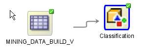
-
Right-click and select Copy from the context menu. Alternately, you can press Ctrl+C to copy the selected nodes.
Note:
Copying and pasting nodes do not carry any mining models or results from the original node.4.4.9.9 Paste
The Paste option pastes the copied object in the workflow. To paste an object, right-click the workflow and click Paste. Alternately, you can press Ctrl+V.
Note:
Node names and model names are changed to avoid naming collisions. To preserve names, use Extended Paste.See Also:
"Copy"4.4.9.10 Extended Paste
The Extended Paste option enables you to preserve node and model names. The default behavior for Paste is to change node names and model names to avoid naming collisions.
To go to the Extended Paste option, right-click the workflow and click Extended Paste. Alternately, you can press Control+Shift+V.
Note:
If model names are not unique, models may be overwritten when they are rebuilt.See Also:
"Copy"4.4.9.11 Generate Apply Chain
Generate Apply Chain creates a new node that contains the specification of a node that performs a transformation. If you have several transformations performed in sequence, for example, Sample followed by a Custom transform, then you must select Generate Apply Chain for each transformation in the sequence.You must connect the individual nodes and connect them to an appropriate data source.
Generate Apply Chain helps you create a sequence of transformations that you can use to ensure that new data is prepared in the same way as existing data. For example, to ensure that Apply data is prepared in the same way as Build data, use this option.
The Generate Apply Chain option is not valid for all nodes. For example, it does not copy the specification of a Build node.
4.4.9.12 Select All
This option enables you to select all the nodes in the workflow. The selected nodes and links are highlighted in a dark blue border.
4.4.9.13 Toolbar Actions
This option enables you to select actions in the toolbar from the context menu. Current actions are Zoom In and Zoom Out.
4.4.9.14 Show Event Log
This option opens the View an Event Log dialog box. The Event Log displays information about events in the current connection. It displays errors, warnings, and information messages.
4.4.9.15 Show Runtime Errors
This option is displayed only when running of the node fails at runtime. The Event Log opens with a list of errors. Select the error to see the exact message and details.
See Also:
"View an Event Log"4.4.9.16 Show Validation Errors
This option is displayed only when there are validation errors. For example, if an Association node is not connected to a Data Source node, select Show Validation Errors to view the validation error No build data input node connected.
You can also view validation errors by moving the mouse over the node. The errors are displayed in a tool tip.
4.4.9.17 Save SQL
The Save SQL option generates a SQL script for the selected node:
-
Right-click the node and click Save SQL.
-
Select any one of the options to save the generated SQL script:
-
SQL to Clipboard
-
SQL to File
-
SQL Script to Clipboard
-
SQL Script to File
When you save to a file, the system provides a default location. You can browse to change this location. You can also create a folder for scripts.
The saved SQL includes SQL generated by the current node and all of its parent nodes that are data providers. The SQL lineage ends when it encounters a node that represents persisted objects, such as tables or models.
The generated script does not generate all behavior of the node. The script does not create any objects. For example, if you select Save SQL for a Create Table node, it does not generate a script to create the table. Instead, it generates a script to query the created table.
-
4.4.9.18 Go to Properties
The Go to Properties option opens the Properties pane for the selected node.
4.4.9.19 Navigate
This option is enabled if there are links to other nodes.
Navigate displays the collection of links available from this node. Picking one of the links selects the link and the selected link is highlighted. The link itself has context menu options as well so you can right click and continue with the Navigate option. You can also use the arrow keys to progress to the next node.
4.4.9.20 View Data
After a Data node is run, the Data Source Node Viewer opens.
4.4.9.21 View Models
Select a model from the list to open the model viewer for that model. A model must be built successfully before it can be viewed.
4.4.9.22 View Test Results
For Classification and Regression models only, select a model and view test results for the model.
4.4.9.23 Compare Test Results
For Classification and Regression models, this option displays the test results for all successfully built models to allow you to pick the model that best solves the problem.
4.5 About Parallel Processing
Oracle Data Miner uses the specifications in a workflow to create SQL queries. These queries are passed and run in the Oracle Database.
In Parallel Query or Parallel Processing, multiple processes work simultaneously to run a single SQL statement. By dividing the work among multiple processes, the Oracle Database can run the statement more quickly. For example, suppose four processes handle four different quarters in a year instead of one process handling all four quarters by itself.
The benefits of Parallel Processing:
-
Reduces response time for data-intensive operations on large databases such as data warehouses.
-
Enhances performance of symmetric multiprocessing (SMP) as statement processing are split up among multiple systems. Certain types of OLTP and hybrid systems also benefit from parallel processing.
In Oracle RAC systems, the service placement of a specific service controls parallel processing. Specifically, parallel processes run on the nodes on which the service is configured. By default, Oracle Database runs parallel processes only on an instance that offers the service used to connect to the database. This does not affect other parallel operations such as parallel recovery or the processing of GV$ queries.
Parallel processing must be configured by a Database Administrator (DBA). For more information on parallel processing in Oracle Database, see:
-
Oracle Database Data Warehousing Guide or Oracle Database VLDB and Partitioning Guide for more information about parallel processing
-
Oracle Real Application Clusters Administration and Deployment Guide for considerations about parallel processing in Oracle RAC environments
4.5.1 Parallel Processing Use Cases
This section lists some common use cases for parallel processing.
4.5.1.1 Building Models in Parallel
Premise of the use case:
-
If the input source for a model is a table defined with parallel and no intervening workflow nodes generate a table that changes this state, then models are built in parallel without any changes to the workflow settings.
-
If the input source is not already defined in parallel, you can still build the model in parallel:
-
For Classification and Regression models: Turn on Parallel Processing for the workflow. The setting for Classification and Regression will be to Split input into Tables with the Parallel option.
-
For all models: Turn on Parallel Processing for the workflow. Insert a Create Table node before the Build node. Use the created table as input to the models.
-
4.5.1.2 Making Transformation Run Faster, using Parallel Processing and Other Methods
You can make transformations run faster by using Parallel Processing and other techniques by:
-
Turning on Parallel Processing for the workflow: All nodes that have a form of sample input could have some benefit. If the sample size is small, then the Oracle Database may not generate parallel queries. But a complex query could still trigger parallel processing.
-
Adding a Create Table node: You can add a Create Table node after expensive transformations to reduce repetitive querying costs.
-
Adding an index to Create Table node: You can add an index to a Create Table node to improve downstream join performance.
4.5.1.3 Running Graph Node in Parallel
You can run Graph nodes in parallel. Even if no other nodes are parallel, performance may improve.
To run Graph node in parallel:
-
Set parallel processing for the entire workflow.
-
Turn off parallel processing for all nodes except for the Graph nodes.
-
Run the Graph nodes. Graph node sample data is now generated in parallel. If the Graph node sample is small or the query is simple, the query may not be made parallel.
4.5.1.4 Running a Node in Parallel to Test Performance
You can run parallel processing on a node just once to see if parallel processing results in improved performance. To run parallel processing:
-
Set parallel processing for the entire workflow.
-
Run the workflow. Note the performance.
-
Now, turn off parallel processing for the workflow.
4.5.2 Oracle Data Mining Support for Parallel Processing
Model scoring is done in parallel for all algorithms and data in Oracle Database 12.1.
All algorithms do not support parallel build. For Oracle Database 12.1, the following algorithms support parallel build:
-
Decision Trees
-
Naive Bayes
-
Minimum Description Length
-
Expectation Maximization
All other algorithms support serial build only.
4.6 Setting Parallel Processing for a Node or Workflow
By default, parallel processing is set to OFF for any node type. Even if parallel processing is set to ON with a preference, the user can override the section for a specific workflow or node.
To set parallel processing for a node or workflow:
-
Right-click the node and select Parallel Query from the context menu. The Edit Selected Node Settings dialog box opens.
-
Click OK.
4.6.1 Edit Selected Node Settings
The Edit Selected Node Settings dialog box lists all the nodes that comprise the workflow. Here, you can:
-
Set parallel processing:
-
For selected nodes: Click the check box in the Parallel column against the nodes for which you want to run parallel query.
-
For all nodes: Click All to select parallel processing for all nodes in the workflow.
-
For none: Click None to deselect all nodes and turn off parallel processing.
-
-
Specify degree of parallelism: Select the node and click
.If you specify parallel processing for at least one node, this indication appears in the workflow title bar:

Parallel Query is either On for Selected nodes, On (for All nodes), or Off. You can click the Parallel Query box to open the Edit Selected Node Settings dialog box.
-
Edit preferences for parallel processing: Click
 to edit the preferences for parallel processing.
4.6.2 Edit Node Parallel Settings
The default degree of parallelism is System Determined. To specify a value:
-
In the Edit Node Parallel Setting dialog box, click the option Parallel Query On to turn on parallel processing for the selected node.
-
Click the option Degree Value and select a higher value. The default value is
1. -
Click OK. The settings are displayed in the Parallel and Degree of Parallel columns for the node.
4.6.3 Editing Parallel Processing Preferences
To edit parallel query preferences:
-
In the Edit Selected Node Settings dialog box, select the node and click
. -
Select any one of the following options:
-
Edit Node Default Settings: To edit the node settings. The Preferences dialog box opens, listing all the nodes. You can select and edit nodes here.
-
Change Settings to Default: To revert the node settings to default.
-
-
Click OK.