About OS Configuration Profiles

OS Configuration profiles define the operating system, network configuration details, host name, and server pool configuration.

The OS Configuration profile enables you to specify and assign the following network resources:

  • Controller

  • Interface

  • Address Allocation Method

  • Network

  • IP address

A server pool is a group of one or more virtualization hosts with the same processor architecture that have access to the same virtual and physical networks, and storage resources. Server pools provide load balancing, high availability capabilities, and sharing of some resources for all members of the pool. Once created, you can edit the server pool settings.

You can create server pools for Oracle VM Server (for SPARC and x86) and for Oracle Solaris Zones. When you want the server to be added to a server pool, you can configure the OS Configuration profile to assign the newly provisioned server to a compatible server pool or you can create a new server pool based on the attributes of the newly provisioned server and assign default server pool settings.

Two advanced network interface options are available for Oracle Solaris and Oracle VM Server for SPARC systems:

  • Link Aggregation: Provides high availability and higher throughput by aggregating multiple interfaces at the MAC layer.

  • IP Multipathing (IPMP): Provides features such as higher availability at the IP layer.

You can implement both methods on the same network because they work at different layers of the network stack.

Defining Link Aggregation in an OS Configuration Profile

Link aggregation groups two or more NICs. All members of the link aggregation provide network access at the same time and are treated as a single network interface. The link aggregation appears in the list of available NICs in the UI as an individual interface.

Link aggregation is a networking option when you create an Oracle Solaris or Oracle VM Server for SPARC OS Configuration profile. You define the link aggregation load balancing policy and a MAC address policy.

  1. Expand Plan Management in the Navigation pane.
  2. Select OS Configuration in the Profiles and Policies tree. A list of existing OS Configuration profiles appears in the center pane.
  3. Click Create Profile in the Actions or center pane.
  4. Name the profile and enter a profile description. Select Solaris as the Subtype and OSP SPARC or OSP x86 as the Target Type. Click Next.
  5. The default setting is to automatically manage the OS with Oracle Enterprise Manager Ops Center and Deploy the Agent Controller. This option provides the most robust management capabilities. If you do not want to enable SAN storage connectivity, deselect Enable Multiplexed I/O (MPxIO). Click Next.
  6. Select Use Link Aggregation for the Networking Services, then click Next.
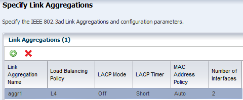
  7. Select a link aggregation name, define the Load Balancing Policy, LACP Mode, MAC Address Policy and the number of link aggregations you want. Click Next.
    • Load Balancing Policy determines the outgoing link:

      • L2: Hashes the MAC (L2) header of each packet

      • L3: Hashes the IP (L3) header of each packet

      • L4: Hashes the TCP, UDP, or other ULP (L4) header of each packet

    • LACP

      Configure the LACP for the switch and aggregation when your link aggregation topology has a switch connection that supports LACP.

    • MAC Address Policy

      • Auto: Use MAC address of any network interfaces in the Link Aggregation.

      • Fixed: Use MAC address of a specific network interface. Select the network interface to use in the next step.

    Figure 7-12 Specify Link Aggregations

    Description of Figure 7-12 follows
    Description of "Figure 7-12 Specify Link Aggregations"
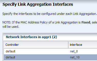
  8. Specify the interface for each link aggregation. The number of interfaces is determined by the number that you defined in step 7. A list of all possible interfaces appears in the wizard. Work with your network administrator to know the interfaces that are available and which interfaces to configure.

    Figure 7-13 Specify Link Aggregation Interfaces

    Description of Figure 7-13 follows
    Description of "Figure 7-13 Specify Link Aggregation Interfaces"
  9. Review the summary of the parameters selected, then click Finish to create the OS Configuration profile for link aggregation.

Defining IPMP in an OS Configuration Profile

IP multipathing (IPMP) groups provide network failover for your Oracle Solaris operating system, Oracle VM Server for SPARC system, and guests.

You can configure one or more physical interfaces into an IPMP group. After configuring the IPMP group, the system monitors the interfaces in the IPMP group for failure. If an interface in the group fails or is removed for maintenance, IPMP migrates, or fails over, the failed interface's IP addresses. The failover feature of IPMP preserves connectivity and prevents disruption of any existing connections. The network access changes from the failed interface to the standby interface in the IPMP group and the data address of the failed interface migrates to the standby interface. See IP Multipathing Groups and Creating IPMP Groups for more information about IPMP groups.
  1. Expand Plan Management in the Navigation pane.
  2. Select OS Configuration in the Profiles and Policies tree. A list of existing OS Configuration profiles appears in the center pane.
  3. Click Create Profile in the Actions or center pane.
  4. Name the profile and enter a profile description. Select Solaris as the Subtype and OSP SPARC or OSP x86 as the Target Type. Click Next.
  5. The default setting is to automatically manage the OS with Oracle Enterprise Manager Ops Center and Deploy the Agent Controller. This option provides the most robust management capabilities. If you do not want to enable SAN storage connectivity, deselect Enable Multiplexed I/O (MPxIO). Click Next.
  6. Select Use IPMP for the Networking Services, then click Next.
  7. Use the default IPMP group name, or click the field and enter a name. Select the Failure Detection Policy, and enter the number of interfaces you want. Click Next.

    Probe based failure detection probes the target systems to determine the condition of the interface. Each target system must be attached to the same IP link as the members of the IPMP group.

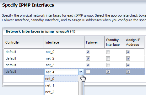
  8. Specify the network interfaces. Select an interface from the list. For each interface, select either the Failover or Standby Interface check box. If you use Link and Probe based failure detection, you do not need to provide test IP addresses. The number of interfaces is determined by the number that you defined in step 7.

    Note:

    A list of all possible interfaces appears in the wizard. Work with your network administrator to know the interfaces that are available and which interfaces to configure.

    Figure 7-15 Specify IPMP Interfaces

    Description of Figure 7-15 follows
    Description of "Figure 7-15 Specify IPMP Interfaces"
  9. Review the summary of the parameters selected, then click Finish to create the OS Configuration profile for IPMP groups.