4 Servicing CRUs That Require Server Node Power Off
These sections describe how to service customer-replaceable units (CRUs) for the Oracle Database Appliance that require you to power off the server node. All of these CRUs are located on the server nodes.
Note:
The servicing of hot-plug components such as the HDDs, SDDs, power supplies, and fans is described in Chapter 3, Servicing CRUs That Do Not Require Server Power Off.Servicing Oracle Database Appliance X6-2 Series CRUs
This section describes how to service customer-replaceable units (CRUs) for Oracle Database Appliance X6-2 series. If you have Oracle Database Appliance X3-2, Oracle Database Appliance X4-2, or Oracle Database Appliance X5-2, go to Servicing Oracle Database Appliance X3-2/X4-2/X5-2 CRUs. If you have Oracle Database Appliance (original version), go to Servicing Oracle Database Appliance (Original Version) CRUs.
This section describes how to service customer-replaceable units (CRUs) that require you to power off the server.
Note:
The links in the following table take you to instructions outside of the Oracle Database Appliance library to the Oracle Server X6-2 documentation library. Use your browser's Back button to return to the Oracle Database Appliance library.| Oracle Database Appliance X6-2S | Oracle Database Appliance X6-2M |
|---|---|
Servicing Oracle Database Appliance X3-2/X4-2/X5-2 CRUs
This section describes how to service customer-replaceable units (CRUs) for Oracle Database Appliance X3-2, Oracle Database Appliance X4-2, or Oracle Database Appliance X5-2. If you have Oracle Database Appliance X6-2 series, go to Servicing Oracle Database Appliance X6-2 Series CRUs. If you have Oracle Database Appliance (original version), go to Servicing Oracle Database Appliance (Original Version) CRUs.
This section describes how to service customer-replaceable units (CRUs) that require you to power off the server.
Note:
All of the CRUs on the storage shelf and the storage expansion shelf can be replaced while the power is on. See Oracle Database Appliance Storage Shelf Hot-Pluggable Components for storage shelf component replacement procedures.Note:
The links in the following table take you to instructions outside of the Oracle Database Appliance library to the Sun Server X3-2, Sun Server X4-2, and Oracle Server X5-2 documentation libraries. Use your browser's Back button to return to the Oracle Database Appliance library.| Oracle Database Appliance X3-2 | Oracle Database Appliance X4-2 | Oracle Database Appliance X5-2 |
|---|---|---|
|
An optional DVD drive for this system is considered a FRU. See Servicing Oracle Database Appliance X3-2/X4-2/X5-2 FRUs.
|
||
|
This system does not include an internal USB flash drive. |
Servicing the Internal USB Flash Drives (CRU)
Note - A factory installed flash drive is reserved for future use. |
Servicing the Internal USB Flash Drives (CRU)
Note - A factory installed flash drive is reserved for future use. |
Servicing Oracle Database Appliance (Original Version) CRUs
This section describes how to service customer-replaceable units (CRUs) for Oracle Database Appliance (original version). If you have Oracle Database Appliance X6-2 series, go to Servicing Oracle Database Appliance X6-2 Series CRUs. If you have Oracle Database Appliance X3-2, Oracle Database Appliance X4-2, or Oracle Database Appliance X5-2, go to Servicing Oracle Database Appliance X3-2/X4-2/X5-2 CRUs.
This section includes information on how to service the following Oracle Database Appliance (original version) CRUs:
Server Node CRU Component Locations
Each server node (also called a system controller) in Oracle Database Appliance (original version) includes the following replaceable components.
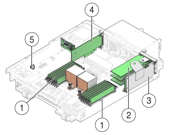
| Callout | Description |
|---|---|
|
1 |
DDR3 Memory DIMMs (12) |
|
2 |
PCIe Cards Mounted on PCIe Riser |
|
3 |
PCIe Riser |
|
4 |
Internal HBA PCIe Card |
|
5 |
Battery |
Servicing Memory Modules (DIMMs) (CRU)
Each server node in Oracle Database Appliance (original version) is provisioned with twelve 1333 MHz or 1600 MHz DDR3, 8GB dual rank DIMMs, for a total of 96GB.
The server node supports a maximum memory speed of 1333 MHz, even if 1600 MHz DIMMs are installed.
Before replacing a DIMM see the following:
DIMM and CPU physical layout.
For details, see DIMM and CPU Physical Layout.
Instructions for removing a faulty DIMM.
For details, see Remove Faulty DIMMs.
Instructions for installing a DIMM.
For details, see Install DIMMs.
Memory Error Correction and Parity
For details, see Error Correction and Parity Protection.
Caution:
These procedures require you to handle components that are sensitive to static discharge. This sensitivity can cause the component to fail. To avoid damage, ensure that you follow antistatic practices as described in Performing Electrostatic Discharge and Antistatic Prevention Measures.
DIMM and CPU Physical Layout
Each processor in Oracle Database Appliance (original version) has six DIMM slots numbered D0 through D5. D0 is the closest to the processor and D5 is the farthest.
Each slot should contain a 1333 MHz or 1600 MHz DDR3, 8GB dual rank DIMM. No other configurations are supported.
The server node supports a maximum memory speed of 1333 MHz, even if it is configured with 1600 MHz DIMMs.
If the system contains a mixture of 1333 MHz and 1600 MHz DIMMs, then P0 and P1 should be configured the same, so that both sides are symmetrical. For example, if you install only two 1600 MHz DIMMs, they should go into P0, D0 and P1, D0.
The following picture shows the physical layout of the DIMMs and CPUs. When viewing the server node from the front, CPU0 (P0) is on the right.
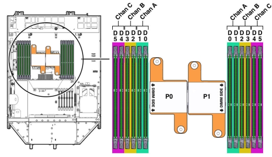
Each processor socket supports three independent memory channels labeled channel A, B, and C, where channel A is closest to the processor socket. Each channel supports two DIMM slots, is controlled by an independent memory controller, and operates independent of the other channels.
Remove Faulty DIMMs
Note:
The DDR3 memory modules (DIMMs) are customer-replaceable units (CRUs) and do not require an Oracle-qualified service person for replacement.- Prepare the server node for service.
- Attach an antistatic wrist strap.
See Performing Electrostatic Discharge and Antistatic Prevention Measures.
- Remove the server node from the system.
Power is removed from the server node when you remove it from the system. See Removing Server Nodes From the System Chassis.
- Remove the server node top cover.
- Attach an antistatic wrist strap.
- Identify the faulty DIMM(s).
- To identify the location of a faulty DIMMs, press the Fault Remind
button on the motherboard.
Note:
When the Fault Remind button is pressed, the Fault Remind Power Good LED lights green to indicate that there is sufficient voltage present in the fault remind circuit to light the fault LEDs. If this LED fails to light when you press the Fault Remind button, the capacitor powering the fault remind circuit has lost its charge. This can happen if the Fault Remind button is pressed for a long time with fault LEDs lit or if the server node has been out of the chassis for more then 15 minutes.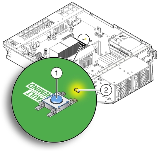
Callout Description 1
Fault Remind Button
2
Fault Remind Power Good LED (green)
- Note the location of faulty DIMMs.
The amber DIMM fault LEDs light if the adjacent DIMM is faulty.
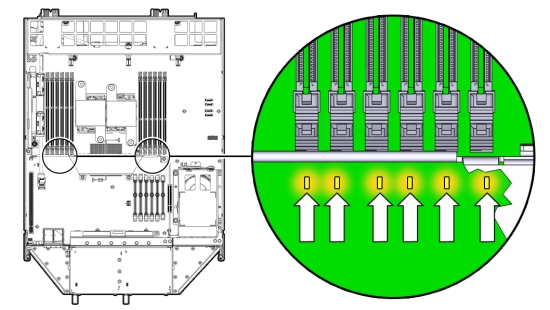
- If the DIMM fault LED is off, the DIMM is operating properly.
- If the DIMM fault Required LED is on (amber), the DIMM is faulty and should be replaced.
- To identify the location of a faulty DIMMs, press the Fault Remind
button on the motherboard.
- To remove the faulty DIMM(s), do the following:
- Rotate both DIMM slot ejectors outward as far as they go.
The ejectors push the DIMM partially up.
- Carefully lift the DIMM straight up to remove it from the socket.
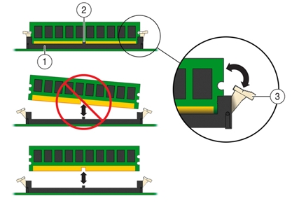
Callout Description 1
DIMM connector slot
2
DIMM connector key
3
DIMM ejector lever
- Rotate both DIMM slot ejectors outward as far as they go.
- Replace each faulty DIMM with either another DIMM of the same
rank size.
For DIMM replacement instructions, see Install DIMMs.
Caution:
Do not operate the system with an empty DIMM slot. If you remove a DIMM, you must replace it before starting the server.
Install DIMMs
- Unpack the replacement DIMMs and place them on an antistatic mat.
- Ensure that the replacement DIMMs match the system requirements.
The system supports only 1333 MHz or 1600 MHz DDR3, 8GB, dual rank DIMMs obtained from Oracle.
For the best performance, if you combine 1333 MHz and 1600 MHz DIMMs in a single system, they should be configured so that P0 and P1 have the same mixture, in the same DIMM slots. For example, in a 1333 MHz system, if you replace P0, D0 with a 1600 MHz DIMM, you should also replace P1, D0 with a 1600 MHz DIMM.
The server node supports a maximum memory speed of 1333 MHz, even if 1600 MHz DIMMs are installed.
- Ensure that the ejector tabs are in the open position.
- Align the replacement DIMM with the connector.
Align the notch in the DIMM with the key in the connector. The notch ensures that the DIMM is oriented correctly.
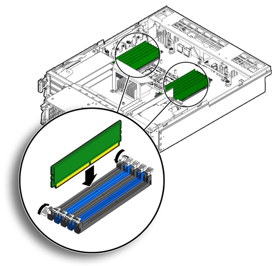
- Push the DIMM into the connector until the ejector tabs lock the
DIMM in place.
If the DIMM does not easily seat into the connector, verify that the notch in the DIMM is aligned with the key in the connector as shown above. If the notch is not aligned, damage to the DIMM might occur.
- Repeat Step 3 through Step 5 until all replacement DIMMs are installed.
- Return the server node to operation.
- Install the server node top cover.
- Install the server node into the system.
- Power on the server node.
See Powering On Oracle Database Appliance (Original Version).
- Clear the DIMM faults.
- Log in to the server node Oracle ILOM CLI as root.
- To view server node faults, type the following command:
-> show /SP/faultmgmt
Oracle ILOM lists all known faults. For example:
SP/faultmgmt
Targets:
0 (/SYS/MB/P0/D2)
Properties:
Commands:
cd
show
- To clear the DIMM fault, type the following command:
-> set /SYS/MB/Px/Dn clear_fault_action=true
For example, to clear a fault on the DIMM in location D2 on CPU0:
-> set /SYS/MB/P0/D2 clear_fault_action=true
Are you sure you want to clear /SYS/MB/P0 (y/n)? y
Set 'clear_fault_action' to 'true'
Error Correction and Parity Protection
The server node's processor provides parity protection on its internal cache memories, and error-correcting code (ECC) protection of the data. The server node detects and posts the following errors to the Oracle ILOM event log:
Correctable and uncorrectable memory ECC errors
Uncorrectable CPU internal errors
Advanced ECC corrects up to 4 bits in error on nibble boundaries, as long as they are all in the same DRAM. If a DRAM fails, the DIMM continues to function.
To clear a fault once the faulty DIMM has been replaced, type the following in the Oracle ILOM CLI:
-> set clear_fault_action=true
For more information on clearing DIMM faults, see the Oracle Integrated Lights Out Manager (Oracle ILOM) 3.0 Documentation Collection: http://www.oracle.com/goto/ILOM/docs.
Servicing PCIe Risers (CRU)
PCIe cards in Oracle Database Appliance (original version) are installed on a vertical riser. You must remove the riser to remove and replace a PCIe card. Also, you must remove the PCIe riser when replacing the motherboard.
This section includes:
Caution:
These procedures require that you handle components that are sensitive to static discharge. This sensitivity can cause the component to fail. To avoid damage, ensure that you follow antistatic practices as described inPerforming Electrostatic Discharge and Antistatic Prevention Measures.Remove PCIe Riser From Server Nodes
- Prepare the server node for service.
- Attach an antistatic wrist strap.
See Performing Electrostatic Discharge and Antistatic Prevention Measures.
- Remove the server node from the system.
Power is removed from the server node when you remove it from the system. See Removing Server Nodes From the System Chassis.
- Remove the server node top cover.
- Attach an antistatic wrist strap.
- If you are servicing a PCIe card, locate its position on the riser.
- Disconnect any data cables connected to the cards on the PCIe riser being removed.
To disconnect a cable from a PCIe card, press the latch, push in toward the connector, and then pull out to remove the cable.
Note the location of all cables for reinstallation later.
- Ensure that the latch adjacent to the location where PCIe riser is installed is in the open
(down) position [1].
If the latch is in the closed position, it prevents you from removing the PCIe riser.
- Loosen the three green captive Phillips screws that secure the PCIe riser to the server node
[1].
Access these screws from the rear of the server node.
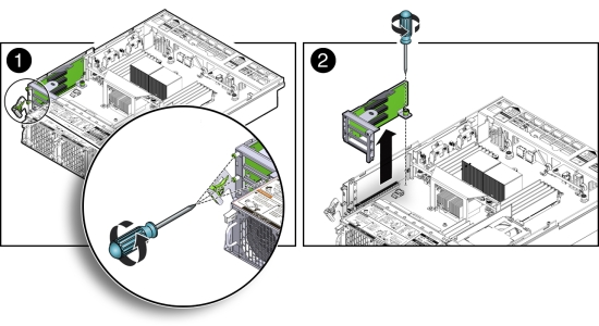
- Loosen the green captive Phillips screw that secures the PCIe riser to the motherboard [2].
- To lift the PCIe riser out of the server node, grasp the front-most side plastic tab with one hand and the rear of the riser with the other hand, and lift it straight up and out of the server node [2].
- Place the PCIe riser and any cards attached to it on an antistatic mat.
Install PCIe Riser in Server Nodes
- Before installing the PCIe riser, ensure that the latch adjacent to the location where PCIe riser is to be installed is in the open (down) position [2].
- Install the PCIe riser.
- Ensure that any PCIe cards installed in the PCIe riser are properly seated, and that the
card's locking bracket is flush with the recess in the riser and is engaging the locking tab.
For instructions for installing a PCIe card into a PCIe riser, see Install PCIe Card in PCIe Riser.
- Lower the PCIe riser and any cards attached to it, into the server node [1].
- Push the PCIe riser down until its connector is seated into the connector on the motherboard.
- Tighten the green captive Phillips screw that secures the riser to the motherboard [1].
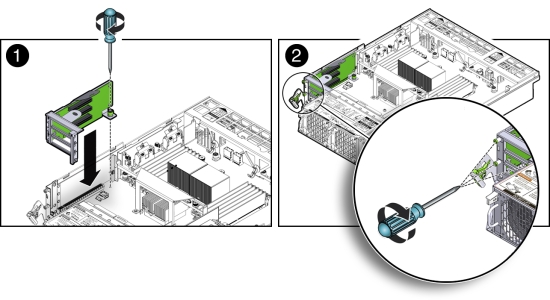
- Tighten the three green captive Phillips screws that secure the PCIe riser to the chassis
[2].
Access these screws from the rear of the server node.
- Ensure that any PCIe cards installed in the PCIe riser are properly seated, and that the
card's locking bracket is flush with the recess in the riser and is engaging the locking tab.
- Return the server node to operation.
- Install the server node top cover.
- Install the server node into the system.
- Reconnect any data cables to the PCIe card connectors on the system rear panel.
- Power on the server node.
See Powering On Oracle Database Appliance (Original Version).
- Clear PCIe riser faults.
- Log in to the Oracle ILOM CLI as root.
- Type:
-> show /SP/faultmgmt
Oracle ILOM lists all known faults. For example:
SP/faultmgmt
Targets:
0 (/SYS/MB/RISER)
Properties:
Commands:
cd
show
- To clear PCIe riser faults, use the set command. For example:
-> set /SYS/MB/RISER clear_fault_action=true
Are you sure you want to clear /SYS/MB/RISER (y/n)? y
Set 'clear_fault_action' to 'true'
Servicing PCIe Cards (CRU)
This section describes servicing PCIe cards in Oracle Database Appliance (original version).
PCIe Card Configuration
The Oracle Database Appliance (original version) PCIe expansion system includes one standalone low-profile slot on the motherboard and a PCIe riser with three slots. These are provisioned as follows:
Motherboard slot – A low-profile, dual-port SAS-2 HBA used internally
PCIe slot 2 – Dual-port SAS-2 HBA used internally
PCIe slot 1 – Quad-port 1-Gb Ethernet NIC
PCIe slot 0 – Dual-port 10-Gb Ethernet NIC
Caution:
If you replace a PCIe card, ensure the replacement is identical to the card you are replacing.Remove PCIe Card From PCIe Riser
- Prepare the server node for service.
- Attach an antistatic wrist strap.
See Performing Electrostatic Discharge and Antistatic Prevention Measures.
- Remove the server node from the system.
Power is removed from the server node when you remove it from the system. See Removing Server Nodes From the System Chassis.
- Remove the server node top cover.
- Attach an antistatic wrist strap.
- Locate the PCIe card in the PCIe riser that you want to remove.
See the "Oracle Database Appliance (Original Version) Back Panel" section of the Oracle Database Owner's Guide for the location of the PCIe slots.
- If necessary, make a note of where the PCIe cards are installed.
- Disconnect all data cables from the PCIe card.
To disconnect a cable from the PCIe card, press the latch, push in toward the connector, and then pull out to remove the cable.
Note the location of all cables for reinstallation later.
- Remove the PCIe riser.
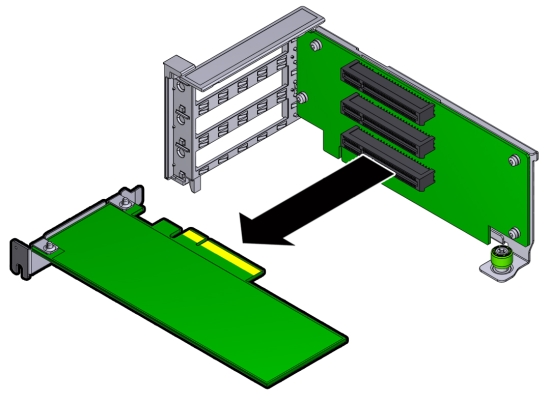
- Remove the PCIe card from the riser.
- Carefully disconnect the PCIe card from the riser connector and
remove it from the riser board connector.
- Place the PCIe card on an antistatic mat.
- Carefully disconnect the PCIe card from the riser connector and
remove it from the riser board connector.
Install PCIe Card in PCIe Riser
- Unpack the replacement PCIe card and place it on an antistatic mat.
- Locate the proper PCIe slot for the card you are replacing.
- Remove the PCIe riser.
- Insert the PCIe card into the correct slot on the riser.
- Press the PCIe card until the locking bracket on the PCIe card is flush with the recessed area on the PCIe riser.
- Slide the locking bracket down until it engages the PCIe riser
locking tab.
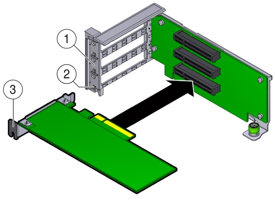
Callout Description 1
Recessed area on the PCIe riser
2
PCIe riser locking tab
3
PCIe card locking bracket
- Install the PCIe riser.
- Reconnect any cables to the PCIe card that you unplugged during the removal procedure.
- Return the server node to operation.
- Install the server node top cover.
- Install the server node into the system.
- Reconnect any data cables to the PCIe card connectors on the system rear panel.
- Power on the server node.
See Powering On Oracle Database Appliance (Original Version).
- Clear the PCIe card fault.
- Log in to the server node as root using the Oracle ILOM CLI.
- To view server node faults, type the following command to list
all known faults on the system:
-> show /SP/faultmgmt
Oracle ILOM lists all known faults, for example:
SP/faultmgmt
Targets:
0 (/SYS/MB/RISER/PCIE2)
Properties:
Commands:
cd
show
- To clear PCIe riser faults, use the set command.
For example:
-> set /SYS/MB/RISER clear_fault_action=true
Are you sure you want to clear /SYS/MB/RISER (y/n)? y
Set 'clear_fault_action' to 'true'
- To clear a PCIe card fault, use the set command. For example,
to clear a fault on PCIe 2:
-> set /SYS/MB/RISER/PCIE2 clear_fault_action=true
Are you sure you want to clear /SYS/MB/RISER/PCIE2 (y/n)? y
Set 'clear_fault_action' to 'true'
Remove Primary HBA PCIe Card From Motherboard
- Prepare the server node for service.
- Attach an antistatic wrist strap.
See Performing Electrostatic Discharge and Antistatic Prevention Measures.
- Remove the server node from the system.
Power is removed from the server node when you remove it from the system. See Removing Server Nodes From the System Chassis.
- Remove the server node top cover.
- Attach an antistatic wrist strap.
- Remove the primary PCIe card.
- Locate the internal PCIe card [1].
The internal PCIe card is located next to the rear-mounted disk drives.
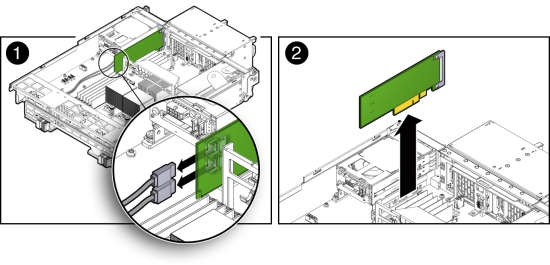
- Disconnect the data cables from the PCIe card [1].
There are two data cables that connect the PCIe card to the server node connector that connects to disk drive backplane.
Note the location of all cables for reinstallation later.
To disconnect the cables from the internal PCIe card, press the latch, push in toward the connector, and then pull out to remove the cable.
- Grasp the PCIe card and lift it up and out of the server node [2].
- Place the PCIe card on an antistatic mat.
- Locate the internal PCIe card [1].
Install Primary HBA PCIe Card in Motherboard
- Unpack the replacement PCIe card and place it on an antistatic mat.
- Install the internal PCIe card.
- Locate the connector for the internal PCIe card [1].
The internal PCIe connector is located next to the rear-mounted disk drives.
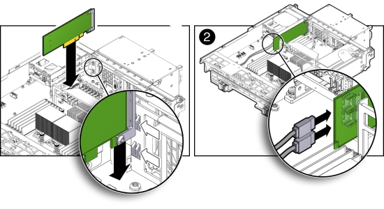
- Align the notch on the PCIe card with the key on the motherboard connector [1].
- Align the rear of the PCIe card with the support bracket located on the rear of the server node [1].
- Press down on the PCIe to seat it into the connector [1].
Caution:
If the notch and key are not aligned, damage to the PCIe card might occur.Note:
To install the primary HBA into the HBA slot on the motherboard, a special PCI metal bracket is required. The standard low-profile metal bracket or full-height metal bracket must be removed from the PCIe card and replaced with the unique metal bracket that is provided with the system. - Reconnect the cables to the PCIe card that you disconnected during the removal procedure [2].
- Locate the connector for the internal PCIe card [1].
- Return the server node to operation.
- Install the server node top cover.
- Install the server node into the system.
- Power on the server node.
See Powering On Oracle Database Appliance (Original Version).
- Clear the primary HBA card fault.
- Log in to the server node as root using the Oracle ILOM CLI.
- To view server node faults, type the following command to list
all known faults on the server node:
-> show /SP/faultmgmt
Oracle ILOM lists all known faults, for example:
SP/faultmgmt
Targets:
0 (/SYS/MB/HBA)
Properties:
Commands:
cd
show
- To clear the internal PCIe card fault, use the set command.
For example:
-> set /SYS/MB/HBA clear_fault_action=true
Are you sure you want to clear /SYS/MB/HBA (y/n)? y
Set 'clear_fault_action' to 'true'
Servicing the Server Node Battery (CRU)
The Oracle Database Appliance (original version) battery maintains the date and time for the Oracle ILOM service processor when the server node is removed from the system and, therefore, is powered off. If the server node fails to maintain the proper time when powered off, replace the battery.
Caution:
These procedures require that you handle components that are sensitive to static discharge. This sensitivity can cause the component to fail. To avoid damage, ensure that you follow antistatic practices as described in Performing Electrostatic Discharge and Antistatic Prevention Measures.Remove Battery
- Prepare the server node for service.
- Attach an antistatic wrist strap.
See Performing Electrostatic Discharge and Antistatic Prevention Measures.
- Remove the server node from the system.
Power is removed from the server node when you remove it from the system. See Removing Server Nodes From the System Chassis.
- Remove the server node top cover.
- Attach an antistatic wrist strap.
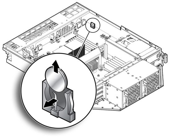
- Remove the battery.
- Place you finger between the battery and the server node side wall and push the battery away from the side wall.
- Twist the battery (either clockwise or counter-clockwise) and
lift it out.
Install Battery
- Unpack the replacement battery.
- Press the new battery into the battery holder with the positive side (+) facing the server node side wall.
- If the service processor is configured to synchronize with a network time server using the Network Time Protocol (NTP), the Oracle ILOM clock is reset as soon as the server node is powered on and connected to the network. Otherwise, proceed to the next step.
- If the service processor is not configured to use NTP, you must reset the Oracle ILOM clock
using the Oracle ILOM CLI or the web interface.
For instructions, see the Oracle Integrated Lights Out Manager (Oracle ILOM) 3.0 Documentation Collection.
- Return the server node to operation.
- Install the server node top cover.
- Install the server node into the system.
- Power on the server node.
See Powering On Oracle Database Appliance (Original Version).