| Oracle® Application Server High Availability Guide 10g Release 3 (10.1.3.1.0) Part Number B28941-03 |
|
|
View PDF |
| Oracle® Application Server High Availability Guide 10g Release 3 (10.1.3.1.0) Part Number B28941-03 |
|
|
View PDF |
This chapter covers high availability solutions for Oracle SOA Suite. Oracle SOA Suite is a set of components that you use for deploying and managing service-oriented architecture systems.
This chapter describes high availability for the following Oracle SOA Suite components:
Installing Oracle SOA Suite components in high availability topologies is a two-step process:
Install the Oracle HTTP Server and OC4J components using the main Oracle Application Server installation CD-ROM.
You do not install Oracle SOA Suite from the main Oracle Application Server CD-ROM.
Be sure you select the Advanced installation option. You cannot use the Basic installation option because this installs the Oracle SOA Suite components. It does not allow you to select which components you want to install. The Basic installation option should be used only to create non-high availability topologies.
Install the Oracle SOA Suite components that you need from the component CD-ROMs. You install the components on top of OC4J.
You use the component CD-ROMs (for example, the Oracle BPEL Process Manager CD-ROM or the Oracle Enterprise Service Bus CD-ROM) to install the components that you need. This enables you to install only the desired components. This is particularly important in the case of Oracle Enterprise Service Bus because in high availability topologies for Oracle Enterprise Service Bus, you have to install the ESB Repository Server and ESB Runtime Server in different Oracle homes.
This section describes high availability for Oracle BPEL Process Manager. It contains the following sections:
Section 5.2.2, "Oracle BPEL Process Manager in an Active-Active Topology"
Section 5.2.3, "Oracle BPEL Process Manager in an Active-Passive Topology"
BPEL (Business Process Execution Language) is an XML-based language that enables you to assemble discrete services into an end-to-end process flow. Oracle BPEL Process Manager provides a framework for designing, deploying, and managing BPEL business processes.
Oracle BPEL Process Manager is a J2EE application that you can run on different application servers. It is a stateless application, but it uses a database as its "dehydration store" to store process state information.
For details on Oracle BPEL Process Manager, see the Oracle BPEL Process Manager Administrator's Guide and the Oracle BPEL Process Manager Developer's Guide.
The Oracle BPEL Process Manager architecture is also stateless, which makes it simple to make highly available. Figure 5-1 shows Oracle BPEL Process Manager in an active-active topology, with a Real Application Clusters database as the dehydration store.
Figure 5-1 Oracle BPEL Process Manager in an Active-Active Topology
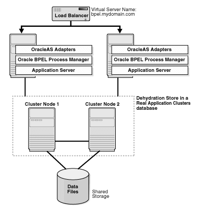
The active-active topology has the following characteristics:
All the components are active (that is, they can all handle requests).
The Oracle Application Server instances are fronted by a load balancer. This can be a software load balancer such as OracleAS Web Cache, but for production purposes, a hardware load balancer such as F5 BIG-IP is recommended. The load balancer distributes requests to one of the active nodes. If the node is unavailable, it sends the request to the next available node.
All the BPEL servers use the same database as their dehydration store.
All the BPEL engines use the load balancer as the server URL and callback address for the generated SOAP URLs. Specifically, use the Oracle BPEL Process Manager Console to set the soapServerUrl and soapCallbackUrl properties to be the URL of the load balancer.
Change any JNDI lookups (for example, to retrieve services) to use a list of JNDI providers returned by OPMN. For example, instead of specifying JNDI providers like this:
jndiProviderURL = "ormi://localhost/Service"
you should use this:
jndiProviderURL = "opmn:ormi://host1:port1:oc4j/Service,
 opmn:ormi://host2:port2:oc4j/Service"
This enables high availability at the JVM level. If you are running multiple JVM processes for a single OC4J instance, OPMN can route requests to independent JNDI objects based on the number of JVMs available.
|
Note: For complete steps for installing and configuring Oracle BPEL Process Manager in an active-active topology, see the "Oracle BPEL Process Manager Clustering" chapter in the Oracle BPEL Process Manager Administrator's Guide. |
BPEL Processes Deployment
To deploy BPEL processes in an active-active topology:
Ensure that all the servers in the cluster have the same domains (as above, this can be done manually or through a script).
To complete the high availability picture, you should run the dehydration store on a highly available database, such as a Real Application Clusters database. With a Real Application Clusters database, then all the components are highly available.
If you are using a Real Application Clusters database for the dehydration store, you need to make the following changes to your configuration:
Modify the OC4J data-sources.xml file so that the connect information to the Real Application Clusters database has the following format:
jdbc:oracle:thin:@(DESCRIPTION=
   (ADDRESS_LIST=(LOAD_BALANCE=on)
      (ADDRESS=(PROTOCOL=tcp)(HOST=hostname1)(PORT=1521))
      (ADDRESS=(PROTOCOL=tcp)(HOST=hostname2)(PORT=1521))
   )
   (CONNECT_DATA=(SERVICE_NAME=orcl))
)
hostname1 and hostname2 specify the names of the nodes running the Real Application Clusters database.
orcl specifies the service name of the database.
Note that both the address and the load balancer options are within the ADDRESS_LIST element.
You can also enable fast connection failover on the Real Application Clusters database. For configuration steps, see section 3.2, "Configuring Fast Connection Failover for the RAC Database on APPHOST1 and APPHOST2", in the Oracle Application Server Enterprise Deployment Guide.
If you are running an active-active topology where the machines are in different subnets, you need to make some changes to the ORACLE_HOME\bpel\system\config\jgroups-protocol.xml file before you can run your topology:
Stop Oracle BPEL Process Manager.
Comment out the first <config> section in the jgroups-protocol.xml file. See (2) in Example 5-1.
Uncomment the second <config> section in the jgroups-protocol.xml file. See (3) in Example 5-1.
Replace hostA and hostB with the actual filenames in the active-active topology. See (4) in Example 5-1.
Restart Oracle BPEL Process Manager.
Example 5-1 Sample jgroups-protocol.xml File
<!-- ************ JGroups Protocol Stack Configuration ************** -->
<!-- generated by XmlConfigurator on Mon Apr 26 11:15:41 PDT 2004 -->
<!-- input file: default.old.xml -->

<!-- (2) Comment out this <config> section. -->
<config>
    <UDP mcast_send_buf_size="32000"
        mcast_port="45788"
        ucast_recv_buf_size="64000"
        mcast_addr="228.8.15.24"
        bind_to_all_interfaces="true"
        loopback="true"
        mcast_recv_buf_size="64000"
        max_bundle_size="48000"
        max_bundle_timeout="30"
        use_incoming_packet_handler="false"
        use_outgoing_packet_handler="false"
        ucast_send_buf_size="32000"
        ip_ttl="32"
        enable_bundling="false"/>
    <PING timeout="2000"
        num_initial_members="3"/>
    <MERGE2 max_interval="10000"
        min_interval="5000"/>
    <FD timeout="2000"
        max_tries="3"
        shun="true"/>
    <VERIFY_SUSPECT timeout="1500"/>
    <pbcast.NAKACK max_xmit_size="8192"
        use_mcast_xmit="false"
        gc_lag="50"
        retransmit_timeout="600,1200,2400,4800"/>
    <UNICAST timeout="1200,2400,3600"/>

    <!--
    - desired_avg_gossip: periodically sends STABLE messages around. 0 disables
              this
    - max_bytes: max number of bytes received from anyone until a STABLE message
              is sent. Use either this or
              desired_avg_gossip, but not both ! 0 disables it.
    - stability_delay: range (number of milliseconds) that we wait until sending a
              STABILITY message.
      This prevents STABILITY multicast storms. If max_bytes is used, this should
              be set to a low value (> 0 though !).
    -->
    <pbcast.STABLE stability_delay="1000"
        desired_avg_gossip="20000"
        max_bytes="0"/>
    <FRAG frag_size="8192"
        down_thread="false"
        up_thread="false"/>
    <VIEW_SYNC avg_send_interval="60000" down_thread="false" up_thread="false" />
    <pbcast.GMS print_local_addr="true"
        join_timeout="3000"
        join_retry_timeout="2000"
        shun="true"/>
</config>
<!-- (2) end of <config> section to comment out -->

<!-- For cluster across subnet, please use the following tcp config and
   - change the initial_hosts instead of the above, the initial_hosts that are
        going to be participating in the cluster.
    -->
<!-- (3) Uncomment this <config> section
<config>
    <TCP start_port="7900" loopback="true" send_buf_size="32000"
             recv_buf_size="64000"/>
<!-- (4) Replace "hostA" and "hostB" with hostnames in your topology.
-->
    <TCPPING timeout="3000" initial_hosts="hostA[7900],hostB[7900]" port_range="3"
             num_initial_members="3"/>
    <FD timeout="2000" max_tries="4"/>
    <VERIFY_SUSPECT timeout="1500" down_thread="false" up_thread="false"/>
    <pbcast.NAKACK gc_lag="100" retransmit_timeout="600,1200,2400,4800"/>
    <pbcast.STABLE stability_delay="1000" desired_avg_gossip="20000"
             down_thread="false" max_bytes="0" up_thread="false"/>
    <VIEW_SYNC avg_send_interval="60000" down_thread="false" up_thread="false" />
    <pbcast.GMS print_local_addr="true" join_timeout="5000"
             join_retry_timeout="2000" shun="true"/>
</config>
--> <!-- (3) end of config section to comment out -->
Oracle BPEL Process Manager can also run in an OracleAS Cold Failover Cluster, or active-passive, topology. An active-passive topology consists of two nodes in a hardware cluster, a shared storage, and a virtual hostname and IP. You install the files on the shared storage so that either node in the hardware cluster can access them. Clients use the virtual hostname to access the active in the hardware cluster. If the active node becomes unavailable, a failover event occurs, and the passive node takes over and runs the processes.
You can use Oracle BPEL Process Manager with Oracle Application Server adapters to integrate your Oracle BPEL Process Manager processes with external resources. These adapters are based on J2EE Connector Architecture (J2CA).
This section describes how to run Oracle BPEL Process Manager with adapters in a highly available manner. This section contains the following subsections:
Oracle Application Server J2CA-based adapters integrate Oracle Application Server with various external resources, as shown in Table 5-1:
Table 5-1 Types of Adapters
| Adapter Type | Examples |
|---|---|
|
Technology |
Technology adapters integrate Oracle Application Server with transport protocols, data stores, and messaging middleware. Examples of technology adapters include: FTP, Files, Database, JMS, and Advanced Queuing. |
|
Packaged application |
Packaged application adapters integrate Oracle Application Server with applications such as Siebel and SAP. |
|
Legacy and mainframe |
Legacy and mainframe adapters integrate Oracle Application Server with applications such as CICS and VSAM. |
For detailed information on adapters, see Oracle Application Server Adapter Concepts.
Concurrency support means that multiple adapter services can access the same resource at the same time without causing any data corruption. You can think of concurrency support as transactional support. For example, multiple adapter services for the database adapter can access the same table in the database at the same time.
Adapters can be divided into those that support concurrency and those that do not:
Adapters that do not support concurrency include the file and FTP adapters. This is because the external resource, which is the file system, does not support concurrent access.
All other adapters support concurrency.
The concurrency/no-concurrency support affects high availability options for the adapters, as shown in Table 5-2.
Table 5-2 High Availability Options for Adapters
| Adapter Type | High Availability Options |
|---|---|
|
Supports concurrency |
|
|
Does not support concurrency (file and FTP adapters) |
|
Note that for all high availability options, it is assumed that you have installed the adapters on all nodes. However, in some of the high availability options, you run Oracle BPEL Process Manager on only one node.
This topology can be used only for adapters that support concurrency.
Figure 5-1 shows this active-active topology. In this topology, you have one or more nodes fronted by a load balancer. On each node, you deploy and run Oracle BPEL Process Manager and business processes. This is the desired model from a high availability point of view, because you have all the components available on all nodes.
If you deploy an adapter that does not support concurrency on an active-active topology, then you risk corrupting the data on the external data source (for example, reading and writing the same file at the same time).
This modified version of an active-active topology is similar to the full active-active topology except for these differences:
You still deploy and run Oracle BPEL Process Manager and business processes on all nodes, but on all nodes except the first node, you disable the Activation Agent for partner links that use adapters that do not support concurrency.
Only the adapter service on the first node gets "receive" requests.
This topology can be used for these adapters:
adapters that do not support concurrency
adapters that support concurrency. Although you can run this type of adapter in a full active-active topology, you choose not to do so because you want to coordinate resources (such as managing and ensuring the proper sequence of messages), and the only way of doing this is to have only one adapter service running at any given time.
Figure 5-2 shows this modified active-active topology.
Figure 5-2 Modified Active-Active Topology
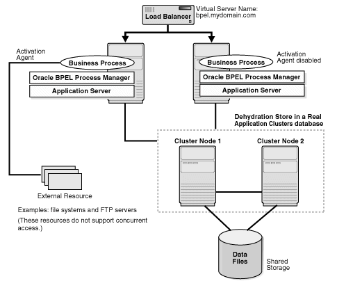
If the node with the Activation Agent fails, then you have to perform these steps:
Disable the Activation Agent on the failed node, so that when the node becomes active again, it will not run the Activation Agent (because another node is already running the Activation Agent).
Enable the Activation Agent on another node.
To Disable an Activation Agent
To disable an Activation Agent, you comment out its activationAgent element in the bpel.xml file. In the following example, the comment lines surround the activation agent that you want to disable.
<activationAgents>
   <!-- start comment
   <activationAgent
                className="oracle.tip.adapter.fw.agent.jca.JCAActivationAgent"
                partnerLink="InboundPL">
      <property name="InputFileDir">C:/ora_home/integration/bpm/samples/tutorials/
                             121.FileAdapter/ComplexStructure/InputDir/</property>
      <property name="portType">Read_ptt</property>
   </activationAgent>
   end comment -->
</activationAgents>
This topology can be used for all adapters. The active-passive topology is also called OracleAS Cold Failover Cluster topology.
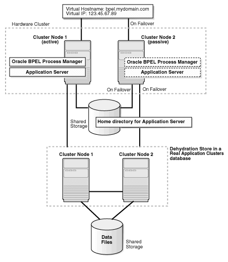
In an active-passive topology (Figure 5-3), you have two nodes in a hardware cluster. One of the nodes is the active node, and the other node is the passive node. There is also a shared storage; you install the Oracle home directories on this shared storage. The shared storage is mounted only on the active node.
The active node in the hardware cluster is associated with a virtual hostname and IP. Clients use the virtual hostname to access the active node in the cluster.
During runtime, the active node runs the processes. The virtual hostname points to the active node. If the active node becomes unavailable, then a failover event occurs. The passive node becomes the new active node and runs the processes.
You install and manage Oracle BPEL Process Manager as you would for a single-node deployment, except for these differences:
You install the Oracle home directories on the shared storage.
Clients access the active node using the virtual hostname. They do not need to know which node is actually running Oracle BPEL Process Manager.
Figure 5-3 Oracle BPEL Process Manager with Adapters in an OracleAS Cold Failover Cluster Topology
This section describes high availability for Oracle Enterprise Service Bus. It contains the following sections:
Section 5.3.2, "Oracle Enterprise Service Bus in an Active-Active Topology"
Section 5.3.3, "Oracle Enterprise Service Bus with Oracle Application Server Adapters"
Oracle Enterprise Service Bus is the foundation for services using SOA and event-driven architecture (EDA). With Oracle Enterprise Service Bus, you can move data among multiple endpoints, both within and outside of an enterprise. Oracle Enterprise Service Bus uses open standards to connect, transform, and route business documents (such as XML messages) among disparate applications. It enables monitoring and management of business data, with minimal impact on existing applications.
Oracle Enterprise Service Bus consists of two main pieces that you have to make highly available:
ESB Runtime Server - runs the ESB services that you have registered.
ESB Repository Server - communicates with the database that contains the ORAESB schema.
Oracle Enterprise Service Bus also includes a Web-based console that you can use for management tasks.
For more information on Oracle Enterprise Service Bus, see these guides:
To run Oracle Enterprise Service Bus in a highly available environment, you can run it in an active-active topology, as shown in Figure 5-4. As with active-active topologies, all the nodes in the topology are active, and you need a load balancer to distribute requests to the active nodes.
Figure 5-4 Oracle Enterprise Service Bus in an Active-Active Topology
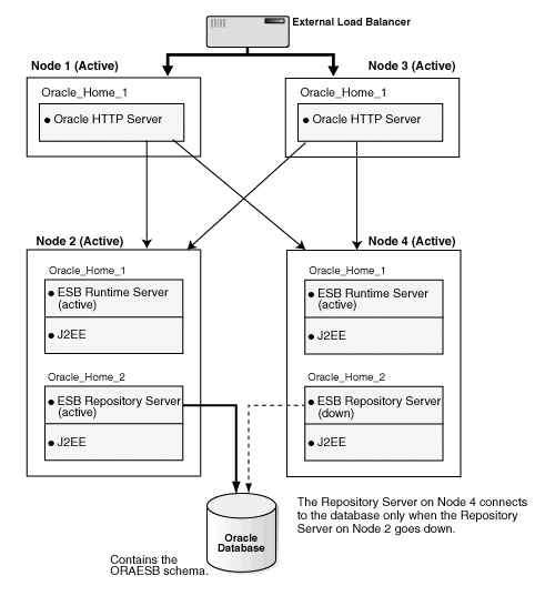
The figure shows four nodes in the active-active topology, but you can have more, if you want, but make sure you understand the following notes:
|
Note 1: In an ESB active-active topology, ensure that only one ESB Repository Server is running at any given time. Other ESB Repository Servers must not be running.To do this:
For details on how to perform the steps listed above, see chapter 3, "Installing and Configuring the mySOACompany Web and Application Tiers", in the Oracle Application Server Enterprise Deployment Guide. All the ESB Runtime Server instances are active, and the Oracle HTTP Server is free to send requests to any of these Runtime Servers. Requests for the ESB Runtime Server use the " |
|
Note 3: In the active-active topology, you cannot run adapters that do not support concurrency (that is, the file and ftp adapters). This is because the external resource, which is the file system in the case of these adapters, does not support concurrent access.See Section 5.2.4.2, "Concurrency Support" for details. |
Installation and Configuration Steps
For detailed steps on building this topology, see chapter 3, "Installing and Configuring the mySOACompany Web and Application Tiers", of the Oracle Application Server Enterprise Deployment Guide. This chapter describes the installation steps and also the post-installation (configuration) steps.
|
Note: After configuring Oracle Enterprise Service Bus Systems with the virtual hostname and port number, you have to restart the ESB Runtime Servers on all the nodes for the updated configuration to take effect. |
One of the post-installation steps (described in chapter 3, "Installing and Configuring the mySOACompany Web and Application Tiers", of the Oracle Application Server Enterprise Deployment Guide) is to rename the ESB cluster for the ESB Runtime Servers. The reason for this is to ensure that the ESB cluster includes ESB Runtime Server instances only. The ESB cluster must not include the ESB Repository Server instance.
To verify this, view the ORACLE_HOME\integration\esb\config\esb_config.ini file in a text editor. Do this for all the Oracle homes where you are running the ESB Runtime Servers and the ESB Repository Server.
Check that all the ESB Runtime Server instances use the same ESB cluster name, and the ESB Repository Server instance uses a different ESB cluster name. The cluster name is specified in the cluster_name parameter in the file. For example:
# Cluster name
cluster_name=ESBcluster1
One of the post-installation steps (described in chapter 3, "Installing and Configuring the mySOACompany Web and Application Tiers", of the Oracle Application Server Enterprise Deployment Guide) is to register the virtual hostname and virtual port (that is, the hostname and port configured on the load balancer) with the ORAESB schema. You can verify these values by running the following command:
ant export-params
       -DDB_URL=jdbc:oracle:thin:@//dbhost:1521/ORCL
       -DDB_USER=oraesb -DDB_PASSWORD=oraesbpassword
dbhost - specifies the machine running the database that contains the ORAESB schema.
1521 - specifies the port at which the database listener is listening.
ORCL - specifies the database service name.
oraesbpassword - specifies the password for the ORAESB schema.
If the values are not correct, rerun the step to register the values.
To create a highly available environment, you need to install the ORAESB schema in a Real Application Clusters database. When you install Oracle Enterprise Service Bus, be sure to enter all the nodes in the Real Application Clusters database when prompted.
You can cluster the OC4J instances in OC4J clusters, but it is not necessary to do so.
You can also use the J2CA-based Oracle Application Server Adapters with Oracle Enterprise Service Bus. High availability topologies for these adapters are described in Section 5.2.4, "Oracle BPEL Process Manager with Adapters".
This section describes running Oracle Business Activity Monitoring in a highly available environment. It contains the following subsections:
Section 5.4.4, "Microsoft Cluster Server (MSCS) Configuration"
Section 5.4.6, "Enterprise Link and Plan Monitor Configuration"
Oracle Business Activity Monitoring collects real-time information from a variety of sources, and filters, transforms, and analyzes the information for its impact on operational metrics and key performance indicators. It can display this data in interactive, real-time dashboards and send out alerts.
To run Oracle Business Activity Monitoring in a highly available environment, you need to make highly available all its components:
Active Data Cache processes data from business sources such as transactional feeds, data warehouses, and other enterprise data sources. Enterprise Link connects Active Data Cache with the data sources.
To make Active Data Cache highly available, you install it on nodes in a hardware cluster. In addition, you configure Active Data Cache to store its data in a Real Application Clusters database.
Failover for Active Data Cache: If a node in a hardware cluster fails, the other node in the hardware cluster takes over. Cluster services monitor the health of Active Data Cache and the active node. If the active node fails or if the Active Data Cache service fails, the cluster services start up Active Data Cache on the other node in the cluster.
In addition to monitoring whether Active Data Cache is running or not, the cluster service also monitors Active Data Cache to make sure that it is not deadlocked.
Enterprise Link connects the Active Data Cache to business data sources. Before sending the data to Active Data Cache, it can process the data incrementally and it can also filter out unwanted data.
To make Enterprise Link highly available, you install it on two (or more) nodes. These nodes are active-active.
Failover for Enterprise Link: If a node running Enterprise Link fails, the remaining active nodes still continue running.
Plan Monitor monitors plans, which contain instructions for locating data sources, manipulating data, and loading data to the Active Data Cache. Plans contain steps called transforms that are linked together to create powerful data flows through Enterprise Link Design Studio. Plans and their status are stored in the Active Data Cache.
To make Plan Monitor highly available, you install it on two (or more) nodes. These nodes are active-active.
Failover for Plan Monitor: If a node running Plan Monitor fails, the remaining active nodes are able to monitor the plans that were being monitored by the failed node.
Web applications (which include the Report Server) apply a report definition to data from the Report Cache in order to transform the data to a format that can be displayed. Web applications work with Microsoft IIS.
To make Web applications highly available, you install it on two (or more) nodes fronted by a load balancer. The load balancer can forward requests to any node.
Failover for Web applications: If a node running Web applications fails, the load balancer stops forwarding requests to that node. The load balancer forwards the requests to the remaining active nodes.
Report Cache caches data from Active Data Cache.
To make Report Cache highly available, you install it on nodes in a hardware cluster. In addition, you configure it to store its data in a Real Application Clusters database.
Failover for Report Cache: If a node in a hardware cluster fails, the other node in the hardware cluster takes over. Cluster services monitor the health of Report Cache and the active node. If the active node fails or if the Report Cache service fails, the cluster services start up Report Cache on the other node in the cluster.
Note that during the failover time (the time that it takes Microsoft Cluster Server to start up the Report Cache on the standby node), Oracle BAM real-time dashboards and reports are not able to display real-time data. How long it takes to fail over depends on your system.
Event Engine monitors the data in Active Data Cache for conditions defined in rules. If a condition is met, it executes the actions associated with the condition. For example, an action might be to send an alert message.
To make Event Engine highly available, you install it on nodes in a hardware cluster. In addition, you configure it to store its data in a Real Application Clusters database.
Failover for Event Engine: If a node in a hardware cluster fails, the other node in the hardware cluster takes over. Cluster services monitor the health of Event Engine and the active node. If the active node fails or if the Event Engine service fails, the cluster services start up Event Engine on the other node in the cluster.
Figure 5-5 shows a highly available topology for Oracle Business Activity Monitoring.
Figure 5-5 High Availability Topology for Oracle Business Activity Monitoring
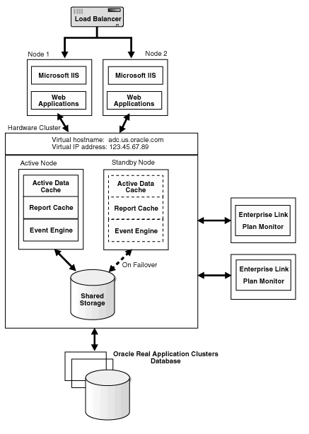
To run Oracle Business Activity Monitoring in a highly available environment, you need the following items:
A load balancer for the Web application nodes. The load balancer is configured with a virtual hostname and port for HTTP traffic. Clients access the Web applications using the virtual hostname/port.
Oracle Real Application Clusters database for Active Data Cache backend
A hardware cluster with two nodes for Active Data Cache
The hardware cluster must be running Microsoft Cluster Server (MSCS) and be configured with a virtual hostname and IP address. One of the nodes in the cluster is active, while the other node is passive. Only one node (the active node) handles requests at any given time. If the active node fails, a failover event takes place and the passive node becomes the active node.
The nodes in the cluster share a storage device. Only the active node can access the shared storage.
This section highlights the key points during installation of the Oracle Business Activity Monitoring components to create the topology shown in Figure 5-5. You can install the components in any order.
For complete details on the Oracle Business Activity Monitoring installer and requirements, see the Oracle Business Activity Monitoring Installation Guide.
This section contains the following subsections:
Section 5.4.3.1, "Active Data Cache, Event Engine, and Report Cache Installation"
Section 5.4.3.3, "Enterprise Link and Plan Monitor Installation"
You install Active Data Cache, Event Engine, and Report Cache on nodes in a hardware cluster. When installing these components, note the following:
Installation and Log Directory screen: specify a directory on the local storage of each node in the hardware cluster. You have to install it in the same directory on each node (for example, C:\OracleBAM as the installation directory and C:\OracleBAM\Logs as the log directory).
Select Components to Install and Configure screen: in addition to selecting the components, expand Active Data Cache and select ADC Clustering Support.
Configure Location of Oracle BAM Components screen: enter the following values:
For Active Data Cache Server, enter the virtual hostname associated with the hardware cluster.
For Report Cache Server, enter the virtual hostname associated with the hardware cluster.
For Event Engine Server, enter the virtual hostname associated with the hardware cluster.
For Web Applications, enter the virtual hostname configured on the load balancer.
Database Connect Information screen: enter the names of all the nodes in the Real Application Clusters database, for example:
nodeA.oracle.com:1521^nodeB.oracle.com:1521^nodeC.oracle.com:1521
Separate the names of the nodes with a ^ character.
You install the Web applications on nodes that are fronted by a load balancer. When installing Web applications, note the following:
Select Components to Install and Configure screen: select Web Applications.
Configure Location of Oracle BAM Components screen: follow the guidelines specified in Section 5.4.3.1, "Active Data Cache, Event Engine, and Report Cache Installation". You should enter the same values in this screen for all component installations in the topology.
When installing Enterprise Link, note the following:
Select Components to Install and Configure screen: select Enterprise Link, Plan Monitor, which is located under Enterprise Link, and Oracle Client. If you do not select Oracle Client, you will get an error.
Configure Location of Oracle BAM Components screen: follow the guidelines specified in Section 5.4.3.1, "Active Data Cache, Event Engine, and Report Cache Installation". You should enter the same values in this screen for all component installations in the topology.
Database Connect Information screen: follow the guidelines specified in Section 5.4.3.1, "Active Data Cache, Event Engine, and Report Cache Installation". You should enter the same values in this screen for all component installations in the topology.
After you have installed the Oracle Business Activity Monitoring components, perform these steps to configure MSCS:
On one of the nodes in the hardware cluster, run the following command (on one line):
cluster.exe restype "Oracle BAM Active Data Cache" /create
            /dll:"C:\OracleBAM\ADCClusterResourceType.dll"
C:\OracleBAM refers to the directory where you installed Oracle Business Activity Monitoring.
You have to run the command on only one of the nodes. It will take effect for every node in the cluster.
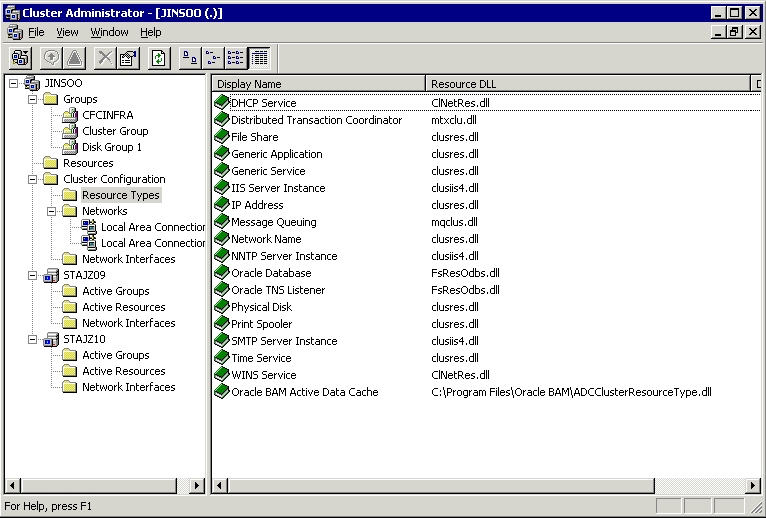
You should see the new resource type in Cluster Administrator.
Start up Cluster Administrator, which is located under Administrative Tools in the Windows Control Panel.
Expand Cluster Configuration and select Resource Types under it. You should see "Oracle BAM Active Data Cache" on the right side.
Figure 5-6 Cluster Administrator Showing "Oracle BAM Active Data Cache"
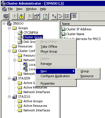
In Cluster Administrator, right-click your cluster group (usually this is the default, which is "Cluster Group"), and select New > Resource from the pop-up menu.
Figure 5-7 Right-click Cluster Group and Select New > Resources
In the New Resource dialog, enter the following values:
Name: enter any value, for example, OracleBAM.
Description: enter any value.
Resource Type: select Oracle BAM Active Data Cache.
Group: select your cluster group.
Click Next.
For possible owner nodes, select all nodes. Click Next.
Add the following dependencies: Cluster Name and Cluster IP Address. Click Finish.
Right-click the new resource and select Bring Online to start the Oracle BAM Active Data Cache.
In Cluster Administrator, right-click your cluster group (usually this is the default, which is "Cluster Group"), and select New > Resource from the pop-up menu.
In the New Resource dialog, enter the following values:
Name: enter any value, for example, BAMRC.
Description: enter any value.
Resource Type: select Generic Service.
Group: select your cluster group.
Figure 5-9 New Resource Dialog for Oracle BAM Report Cache
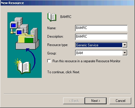
Click Next.
For possible owner nodes, select all nodes. Click Next.
Add the following dependencies: Cluster Name and Cluster IP Address. Click Next.
In the Generic Service Parameters dialog, enter the following values:
Service Name: enter Oracle BAM Report Cache
Start Parameters: BAM_HOME\OracleBAMReportCache.exe (for example, C:\OracleBAM\BAM\OracleBAMReportCache.exe).
Use Network Name for Computer Name: do not select.
Figure 5-10 Generic Service Parameters Dialog for Oracle BAM Report Cache
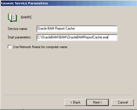
Click Finish, and right-click the new resource and select Bring Online to start the Oracle BAM Report Cache.
In Cluster Administrator, right-click your cluster group (usually this is the default, which is "Cluster Group"), and select New > Resource from the pop-up menu.
In the New Resource dialog, enter the following values:
Name: enter any value, for example, BAMEE.
Description: enter any value.
Resource Type: select Generic Service.
Group: select your cluster group.
Figure 5-11 New Resource Dialog for Oracle BAM Event Engine
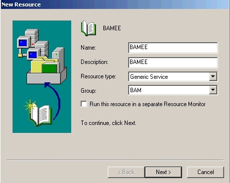
Click Next.
For possible owner nodes, select all nodes. Click Next.
Add the following dependencies: Cluster Name and Cluster IP Address. Click Next.
In the Generic Service Parameters dialog, enter the following values:
Service Name: enter Oracle BAM Event Engine
Start Parameters: BAM_HOME\OracleBAMEventEngine.exe (for example, C:\OracleBAM\BAM\OracleBAMEventEngine.exe).
Use Network Name for Computer Name: do not select.
Figure 5-12 Generic Service Parameters Dialog for Oracle BAM Event Engine
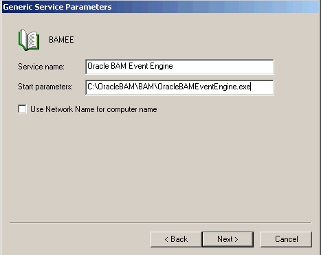
Click Finish, and right-click the new resource and select Bring Online to start the Oracle BAM Event Engine.
A Web garden consists of multiple worker processes. Perform these steps to set up a Web garden for the Web applications:
In IIS Manager, expand local computer and Application Pools.
If you do not see Application Pools, verify that the Run WWW Service in IIS 5.0 Isolation Mode option is not selected. This option is located under Web Sites > Properties > Service tab.
Right-click application pool and select Properties from the pop-up menu.
Select the Performance tab.
Under Web Garden, in the Maximum Number of Worker Processes field, enter the number of worker processes for the application pool. The number of worker processes must be greater than 1.
Click OK.
For information on Web gardens, see the following page: http://www.microsoft.com/technet/prodtechnol/WindowsServer2003/Library/IIS/659f2e2c-a58b-4770-833b-df96cabe569e.mspx?mfr=true
When you run multiple instances of Enterprise Link and Plan Monitor on multiple nodes in an active-active configuration, you have to use the Oracle Business Activity Monitoring Architect to assign specific plans to each instance of Enterprise Link and Plan Monitor.
See Section 3.7, "Installing Multiple Plan Monitors", in the Oracle Business Activity Monitoring Installation Guide for configuration steps.
For information on running Oracle Business Activity Monitoring Architect, see the Oracle Business Activity Monitoring Architect User's Guide.
Be aware of the following issues when running Oracle Business Activity Monitoring in a high availability topology:
Section 5.4.7.1, "Enterprise Link Throws Error When Cluster Node Fails"
Section 5.4.7.3, "Potential Data Loss When a Node in the Real Application Clusters Database Fails"
Section 5.4.7.4, "Plan Monitor Does Not Reconnect to Active Data Cache or Data Flow Service (DFS)"
Section 5.4.7.5, "Plan Monitor Does Not Reconnect Automatically to Enterprise Link"
Section 5.4.7.6, "ICommand Gives Error When Run on Standby Node in the Hardware Cluster"
Section 5.4.7.8, "Fast Connection Failover (FCF) Not Supported"
Problem
When a node in the hardware cluster running Active Data Cache fails, and a failover event completes successfully (that is, Active Data Cache is started on the other node), Enterprise Link is not processing the messages in the queue and log. However, it is still running the plan even after the failover event is complete.
You may also see the following error in Enterprise Link:
You are unable to connect to the Oracle BAM services. Contact your system
administrator if the error persists.
[ErrorSource="ActiveDataCache", ErrorID="ADCServerConnectionError"]
No connection could be made because the target machine actively refused it
[Error Source="mscolib"]
Solution
If you are getting the error in Enterprise Link, ensure that you are using Message Integrity feature (also called the Guaranteed Messaging feature) for your plan. Activating the Message Integrity feature will stop the error. See Section 5.4.8, "Message Integrity Setup" for steps on how to enable this feature.
To resume message processing, restart these components in the following order:
Active Data Cache
Data Flow Service
Plan Monitor. If the plan is not being monitored, re-execute the plan.
Problem
When a node in the hardware cluster running Active Data Cache fails, and a failover event completes successfully (that is, Active Data Cache is started on the other node), the Active Viewer displays an error ("You are unable to connect to the Oracle BAM Services") when you try to drill down on a chart or perform any other action. The Active Viewer was connected to the hardware cluster before the node failure and failover event occurred.
Solution
Re-open the report in Active Viewer to view it.
Problem
When a node in the Real Application Clusters database fails, you get the following error:
An error has occurred in the ADC storage system. ORA-01089: immediate
shutdown in progress – no operations are permitted
[ErrorSource="ActiveDataCache", ErrorID="ADCStorageException"]
The error can occur in different components, such as Enterprise Link, Plan Monitor, or Active Data Cache.
The node failure also stops any plans that were running at that time.
Solution
Currently there is no workaround. After the node failover, you should check the logs to be sure that all the data have been accounted for and that no data got lost.
Problem
When the Plan Monitor loses its connection to Active Data Cache or to the DFS (for example, if the network connection is lost), the Plan Monitor writes a message to the Event Log and suspends processing. The message looks like the following:
2006-03-10 10:46:32,808 [2472] ERROR - PlanMonitor Plan Monitoring
processing suspended. Service must be restarted.
[ErrorSource="PlanMonitor", ErrorID="PlanMonitor.BackgroundFatal"]
An error has occurred in the ADC storage system. ORA-03113:
end-of-file on communication channel
[ErrorSource="ActiveDataCache", ErrorID="ADCStorageException"]
Solution
You have to manually stop and restart the Plan Monitor.
Problem
If Plan Monitor loses its connection to Enterprise Link, it does not automatically reconnect.
Solution
Restart Plan Monitor.
Problem
When you run icommand.exe on the standby node in the hardware cluster, you get an error like the following:
> ICommand.exe cmd=import file=sla_adherence_stage.xml
Oracle BAM Command Utility
10g Release 3 (10.1.3.1.0) [Build 3 5 5777 0, ADC Version 1003.0]
Copyright (c) 2002, 2006 Oracle.
All rights reserved.
Error while processing command "import".
  [ErrorSource="ICommandEngine", ErrorID="ICommandEngine.Error"]
You are unable to connect to the Oracle BAM services. Contact your system
administrator if the error persists.
  [ErrorSource="ActiveDataCache", ErrorID="ADCServerConnectionError"]
Requested Service not found
  [ErrorSource="System.Runtime.Remoting"]
Solution
Run icommand.exe on the active node.
Problem
If a rule or condition specified for an alert is met during the time it takes Microsoft Cluster Server to fail over the services from the active node to the standby node, the alert may not get fired.
Solution
After the failover is complete, verify that all the alerts that should have been launched were launched. If not, you can launch the alerts manually.
In this release, Oracle Business Activity Monitoring does not support Fast Connection Failover.
Message integrity gives messages a chance to be reprocessed in the event of a failure. To set up a plan for message integrity, perform these steps:
Section 5.4.8.1, "Select "Run Forever" in the Oracle BAM Enterprise Message Receiver Dialog"
Section 5.4.8.2, "Set the Subplan to Iterate for each Record"
Section 5.4.8.3, "Include the Transform in a Global Transaction"
Section 5.4.8.4, "Include Message Tracker in Global Transaction"
About Message Integrity
Message integrity gives messages a chance to be reprocessed in the event of a failure, particularly the failure described in Section 5.4.7.1, "Enterprise Link Throws Error When Cluster Node Fails". You should understand the sequence of events so that you know when message reprocessing is possible.
Messages are read from a queue and logged into a message log data object. Each message has its own ID, which is used by the Message Tracker transform for each transaction made to the Active Data Cache.
If a failure occurs before the message is logged in the message log data object, the message is not removed from the queue. No reprocessing is necessary because the message has not been processed yet.
If a failure occurs after the message is logged in the message log data object and removed from the queue, but the plan fails to finish processing the message, the message has a chance to be reprocessed.
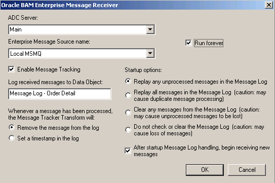
In the Oracle BAM Enterprise Message Receiver dialog (Figure 5-13), select these options:
Run Forever option. This option enables the plan to run continuously and feed live data continuously into a data object. The plan must also be monitored.
Enable Message Tracking option
Under startup options, either Replay any unprocessed messages in the Message Log or Replay all messages in the Message Log (caution: may cause duplicate message processing)
Figure 5-13 Select "Run Forever" and "Enable Message Tracking" in the Oracle BAM Enterprise Message Receiver Dialog
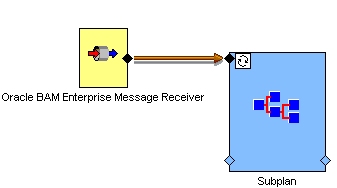
Create a subplan and set it to iterate for each record.
Figure 5-14 shows the connector from the message receiver to the top connector of the subplan.
Figure 5-14 Connector from Oracle BAM Enterprise Message Receiver to the Subplan
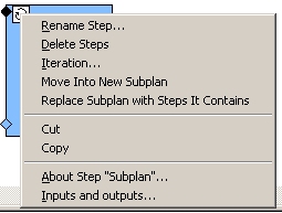
Right-click the iteration icon on the subplan and select Iteration from the pop-up menu (Figure 5-15).
Figure 5-15 Pop-up Menu for the Iteration Icon on the Subplan
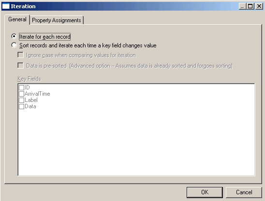
In the Iteration dialog, select Iterate for each record (Figure 5-16).
Figure 5-16 Select "Iterate for each Record" in the Iteration Dialog
Select the Include in Global Transaction option so that the plan handles each message or row inside the iterating subplan as a transaction (Figure 5-17).
Figure 5-17 Select "Include in Global Transaction" and Provide a Name

This option can be found in the following dialogs:
Oracle BAM Insert dialog
Oracle BAM Update dialog
Oracle BAM Delete dialog
Oracle BAM Lookup dialog
You need to give the global transaction a name. This name must be the same for all transforms within the subplan.
In the Oracle BAM Message Tracker dialog, also select the Include in Global Transaction option, and enter the same name that you used for the transforms (Figure 5-18).
Figure 5-18 Select "Include in Global Transaction" and Provide a Name
Figure 5-19 shows how the transforms would appear in an iterating subplan.
Figure 5-19 Transforms Within an Iterating Subplan
Oracle Service Registry is a UDDI (Universal Description, Discovery and Integration) registry of Web services. Clients can query Oracle Service Registry to determine the location of Web services. Clients can also register Web services with the registry.
For details on Oracle Service Registry, see the product documentation provided with the application.
Oracle Business Rules is not a runnable component, that is, it does not run as a process or service. Rather, it is a library that applications can use. If you have applications that use Oracle Business Rules, high availability for Oracle Business Rules depends on the high availability environment in which you have deployed your application. Oracle Business Rules can work in active-active or active-passive high availability environments.
For complete information on Oracle Business Rules, see the Oracle Business Rules User's Guide.
This section covers the following topics:
Section 5.6.3, "Real Application Clusters Database and Oracle Business Rules"
Section 5.6.4, "Rule Author in High Availability Environments"
You should use a WebDAV-based repository instead of a file repository in production environments. WebDAV repositories are more secure than file repositories. File repositories should be used only in development environments.
Before you can specify a WebDAV repository in Rule Author, you must have created the repository. (Rule Author does not create the repository.) The repository must be on the same file system as Oracle HTTP Server. Oracle HTTP Server supports WebDAV through the ORADAV (mod_oradav) module.
Then in Rule Author, when you enter the URL to the repository, you use the fully qualified physical host name (of the host running Oracle HTTP Server).
During runtime, you also need to specify a URL path to the repository. You enter a URL that all the nodes can use to access the repository.
Oracle Business Rules itself does not use the database. However, you could utilize the WebDAV support built into Oracle XML DB and configure a WebDAV repository in Oracle XML DB.
Rule Author is a browser-based tool that enables you to create and modify rules. It is a J2EE application, which can be deployed on multiple instances. Note the following points:
It is not safe for multiple users to edit the same dictionary at the same time.
Only one instance should be used to modify rules. This can be enforced by, for example, enabling sticky routing on the load balancer.
You access Rule Author using the physical hostname in the URL. A WebDAV repository resides on a single node and thus the physical hostname is required in the URL. This should not be a problem because you would typically use Rule Author from an internal machine to access the repository.
For high availability information for Oracle Web Services Manager, see the section "Configuring Oracle WSM in a Clustered Environment" in the Oracle Web Services Manager Deployment Guide.