| Oracle® Application Server Adapters for Files, FTP, Databases, and Enterprise Messaging User's Guide 10g Release 3 (10.1.3.1.0) Part Number B28994-02 |
|
|
View PDF |
| Oracle® Application Server Adapters for Files, FTP, Databases, and Enterprise Messaging User's Guide 10g Release 3 (10.1.3.1.0) Part Number B28994-02 |
|
|
View PDF |
This chapter describes how to use the Oracle Application Server Adapter for Advanced Queuing (AQ adapter), which enables a BPEL process or an ESB service to interact with a queue.
This chapter contains the following topics:
Section 3.3, "AQ Adapter Use Cases for Oracle BPEL Process Manager"
Section 3.4, "AQ Adapter Use Cases for Oracle Enterprise Service Bus"
Oracle Streams Advanced Queuing (AQ) provides a flexible mechanism for bidirectional, asynchronous communication between participating applications. Because advanced queues are an Oracle database feature, they are scalable and reliable. Backup and recovery (including any-point-in-time recovery), logging, transactional services, and system management are all inherent features of the database and, therefore, advanced queues. Multiple queues can also service a single application, partitioning messages in a variety of ways and providing another level of scalability through load balancing. See Oracle Streams Advanced Queuing User's Guide and Reference for more information.
This section comprises the following topics:
The AQ adapter is both a producer and consumer of AQ messages. The enqueue operation is exposed as a JCA outbound interaction. The dequeue operation is exposed as a JCA inbound interaction.
The AQ adapter supports both ADT (Oracle object type) and RAW queues as payloads. It also supports extracting a payload from one ADT member column. The AQ adapter does not support the AQ XML type.
The AQ adapter supports headers for enqueue and dequeue options. Headers are comprised of an AQ header and a payload header. The AQ header consists of the standard message properties that are present in every queue.
You access the AQ adapter from the Adapter Configuration Wizard, which you use to browse queues and expose the underlying metadata as a WSDL with JCA extensions.
For AQ adapter samples, go to
Oracle_Home\bpel\samples\tutorials\124.AQAdapter
The AQ adapter supports the following features of Oracle Streams AQ:
In the Adapter Configuration Wizard, you can specify a correlation identifier when defining an enqueue operation, which you use to retrieve specific messages.
In Oracle Streams AQ, more than one consumer can process and consume a single message. To use this feature, you must create multiconsumer queues and enqueue the messages into these queues. In this configuration, a single message can be consumed by more than one AQ consumer (dequeue operation), either through the default subscription list or with an override recipient list. Under this scenario, a message remains in the queue until it is consumed by all of its intended consumer agents. The AQ adapter enqueue header enables you to specify the override recipient list (string values separated by commas) that can retrieve messages from a queue. All consumers that are added as subscribers to a multiconsumer queue must have unique values for the Recipient parameter. This means that two subscribers cannot have the same values for the NAME, ADDRESS, and PROTOCOL attributes.
If you specify the priority of enqueued messages, then the messages are dequeued in priority order. If two messages have the same priority, the order in which they are dequeued is determined by the enqueue time. You can also create a first-in, first-out (FIFO) priority queue by specifying the enqueue time priority as the sort order of the messages. This priority is a property of the AQ adapter enqueue header. The enqueue time is set automatically by the underlying AQ application.
Here is an example of how to create the FIFO queue:
EXECUTE DBMS_AQADM.CREATE_QUEUE_TABLE( \
queue_table => 'OE_orders_pr_mqtab', \
sort_list =>'priority,enq_time', \
comment => 'Order Entry Priority \
MultiConsumer Orders queue table',\
multiple_consumers => TRUE, \
queue_payload_type => 'BOLADM.order_typ', \
compatible => '8.1', \
primary_instance => 2, \
secondary_instance => 1);
EXECUTE DBMS_AQADM.CREATE_QUEUE ( \
queue_name => 'OE_bookedorders_que', \
queue_table => 'OE_orders_pr_mqtab');
Time specification and scheduling
In Oracle Streams AQ, you can specify a delay interval and an expiration interval. The delay interval determines when an enqueued message is marked as available to the dequeuers after the message is enqueued. When a message is enqueued with a delay time set, the message is marked in a WAIT state. Messages in a WAIT state are masked from the default dequeue calls. The expiration time property is used to specify an expiration time and the message is automatically moved to an exception queue if the message is not consumed before its expiration. The delay interval, expiration time, and exception queue property are properties of the AQ adapter enqueue header.
Oracle Streams AQ provides the following dequeuing options:
Poll option
Notification option
The poll option involves processing the messages as they arrive and polling repeatedly for messages. The AQ adapter supports a polling mechanism for consuming AQ messages.
The AQ adapter supports the following features of Oracle Streams AQ:
Multiconsumer queue
The AQ adapter can retrieve messages from a multiconsumer queue.
Navigation of messages for dequeuing
Messages do not have to be dequeued in the same order in which they were enqueued. You can use a correlation identifier to specify dequeue order. The Adapter Configuration Wizard defines the correlation ID for the dequeue operation.
Retries with delays
The number of retries is a property of the AQ adapter dequeue header. If the number of retries exceeds the limit, the message is moved to an exception queue that you specify. The exception queue is a property of the AQ adapter enqueue header.
Rule-based subscription
Oracle Streams AQ provides content-based message filtering and subject-based message filtering. A rule defines one or more consumers interest in subscribing to messages that conform to that rule. For a subject-based rule, you specify a Boolean expression using syntax similar to the WHERE clause of a SQL query. This Boolean expression can include conditions on message properties (currently priority and correlation ID), user data properties (object payloads only), and functions (as specified in the WHERE clause of a SQL query).
AQ headers
Table 3-1 summarizes the AQ header properties for the enqueue and dequeue operations.
Table 3-1 AQ Header Message Properties
| Message Property | Datatype | Default If Not Specified | Description | Include in Message Header for Enqueue | Include in Message Header for Dequeue |
|---|---|---|---|---|---|
|
|
Integer |
1 |
Priority of the message. A smaller number indicates a higher priority. |
Yes |
Yes |
|
|
Integer |
0 |
The number of seconds after which the message is available for dequeuing |
Yes |
No |
|
|
Integer |
-1 (never expires) |
The number of seconds before the message expires. This parameter is an offset from the delay. |
Yes |
No |
|
|
String |
- |
User-assigned correlation ID |
Yes |
Yes |
|
|
String |
- |
The list of recipients for this message, separated by commas. This overrides |
Yes |
No |
|
|
String |
- |
The exception queue name |
Yes |
No |
|
|
String |
- |
The time at which the message was enqueued |
No |
Yes |
|
|
String |
- |
The hexadecimal representation of the message ID |
No |
Yes |
|
|
String |
- |
The hexadecimal representation of the original message ID |
No |
Yes |
|
|
Integer |
- |
The number of failed attempts at dequeuing the message |
No |
Yes |
See Oracle Application Server Adapter Concepts for information on AQ adapter architecture, adapter integration with Oracle BPEL Process Manager, and adapter deployments.
The AQ adapter supports the following RAW types:
BLOB
CHAR
CLOB
DATE
DECIMAL
DOUBLE PRECISON
FLOAT
INTEGER
NUMBER
REAL
SMALLINT
TIMESTAMP
VARCHAR2
In addition, the primitive types, varrays of objects, or primitives are also supported.
Note:
The AQ Adapter does not currently support the following data types for ADT columns:TIMESTAMP WITH LOCAL TIMEZONE and TIMESTAMP WITH TIMEZONE.If choosing a payload field instead of the whole ADT, choose only one of the following datatypes as the payload field:
CLOB, either XSD or opaque schema
VARCHAR2, either XSD or opaque schema
BLOB, opaque schema only
JDeveloper BPEL Designer provides the Native Format Builder Wizard to define XSD files of various formats, including for the AQ RAW payload. See Chapter 7, "Native Format Builder Wizard" for more information. For Native Format Builder examples, go to
Oracle_Home\bpel\samples\tutorials\124.AQAdapter\
RawQueuePayloadUsingNativeFormat
The payload schemas depend on the payload type. In the whole ADT case, the schema is completely generated by the Adapter Configuration Wizard. In the ADT with BLOB selected as the payload case, an opaque schema must be used, which is defined as:
<element name="opaqueElement" type="base64Binary" />
In all other cases, you can either provide a schema or use an opaque schema, as shown in Table 3-2.
Table 3-2 Payload Schema
| Payload Type | Supported Schema |
|---|---|
|
RAW |
User-provided schema or opaque schema |
|
Whole ADT |
Must use a schema generated by the Adapter Configuration Wizard, which is based on the queue structure |
|
ADT with |
User-provided schema or opaque schema |
|
ADT with |
User-provided schema or opaque schema |
|
ADT with |
Opaque schema |
If you do not have an XSD, but the payload data is formatted in some way (for example, in a comma-separated value (CSV) format), then the Native Format Builder Wizard can be used to generate an appropriate XSD. The Adapter Configuration Wizard is integrated with the Native Format Builder Wizard. In the Adapter Configuration Wizard - Messages window, click Define Schema for Native Format to access the Native Format Builder Wizard.
Adapter Framework is used for the bidirectional integration of the J2CA 1.5 resource adapters with BPEL Process Manager. Adapter Framework is based on standards and employs the Web service Invocation Framework (WSIF) technology for exposing the underlying J2CA interactions as Web services.
See Oracle Application Server Adapter Concepts for information on AQ adapter architecture, adapter integration with Oracle BPEL Process Manager, and adapter deployments.
Oracle Enterprise Service Bus Server supports the Oracle adapters and enables you to define inbound and outbound adapter services for each. An inbound adapter service receives data from an external data source and transforms it into an XML message. An outbound adapter service sends data to a target application by transforming an XML message into the native format of the given adapter.
Using Oracle Enterprise Service Bus Server you can send or receive messages from Oracle Advanced Queuing single or multiconsumer queues.
BPEL pre-dates ESB and most of this guide and the samples implicitly assume use with BPEL. However, the adapters work equally well with either BPEL or ESB. For any mention of BPEL here you may substitute ESB instead.
The following use cases include a general walkthrough of the Adapter Configuration Wizard, followed by examples of how you modify the general procedure in different situations. Each example shows relevant parts of the generated WSDL file.
This section comprises the following topics:
The following use cases include a configuring AQ adapter, followed by examples of how you modify the generic procedure in different situations. Each example shows relevant parts of the generated WSDL file.
In this example you will create an adapter service that enqueues messages to the CUSTOMER_IN_QUEUE queue, with a payload that is one field within the CUSTOMER_TYPE object (the customer's e-mail address), and with a user-defined schema.
This section describes the tasks required to configure AQ adapter using the Adapter Configuration Wizard in Oracle JDeveloper.
This section comprises the following:
The following prerequisites have to be met before you create the sample service:
Access SCOTT schema in some database.
Find data-sources.xml in
C:\product\10.1.3.1\OracleAS_1\bpel\system\appserver\oc4j\j2ee\home\config\data-sources.xml
Add the following code to data-sources.xml to define the data source for jdbc/aqSample. Note that URL should refer to the endpoint database that we use.
<connection-pool name="aqSample_CONNECTION_POOL">
 <connection-factory factory-class="oracle.jdbc.OracleDriver"
url="jdbc:oracle:thin:scott/tiger@stadd14:1521:db5617"/>
 </connection-pool>
 <managed-data-source name="AQSamplesDataSource"
 connection-pool-name="aqSample_CONNECTION_POOL" jndi-name="eis/AQ/MyConnection" />
The first configuration task is to create a new BPEL project. Use the following steps to create a new BPEL project:
Open Oracle JDeveloper
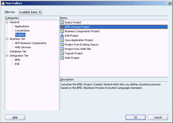
From the File menu, select New. The New Gallery dialog box is displayed.
Select All Technologies from the Filter By box. This displays a list of available categories.
Expand the General node, and then select Projects.
Select BPEL Process Project from the Items group, as shown in Figure 3-1.
Figure 3-1 Creating a New BPEL Process Project
Click OK. The BPEL Process Project dialog box is displayed.
In the BPEL Process Name field, enter a descriptive name. For example, CustomerDetails.
From the Template box, select Asynchronous BPEL Process.
The Input/Output Elements dialog box is displayed, as shown in .
Figure 3-2 The Input/Output Elements Dialog Box
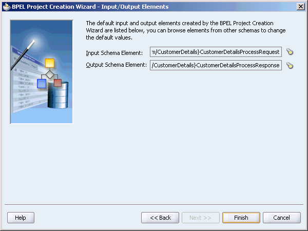
Retain the default values for the schemas, and then click Finish.
A new BPEL process, with the required source files including bpel.xml, CustomerDetails.bpel, and CustomerDetails.wsdl is created, as shown in Figure 3-3.
The next task is to add a partner link to the BPEL process. A partner link defines the link name, type, and the role of the BPEL process that interacts with the partner service.
Use the following steps to add a partner link:
Select BPEL Activities from the Component Palette, and then drag and drop PartnerLink into the border area of the process diagram. The Create Partner Link dialog box is displayed.
Click the Define Adapter Service icon (third icon) in WSDL Settings. The Adapter Configuration Wizard is displayed.
Click Next. The Adapter Type dialog box is displayed.
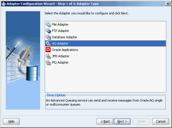
Select AQ Adapter, as shown in Figure 3-4, and then click Next.
Figure 3-4 Selecting OracleAS Adapter for Oracle Applications
The Service Name dialog box is displayed, as shown in Figure 3-5. Enter the following information:
In the Service Name field, enter a service name.
In the Description field, enter a description for the service. This is an optional field. Click Next.
The Service Connection dialog box is displayed. Enter the Java Naming and Directory Interface (JNDI) name in the Database Server JNDI Name field. The JNDI name acts as a placeholder for the connection used when your service is deployed to the BPEL server. This enables you to use different databases for development and later production.
See Also:
Oracle Application Server Adapter Concepts Guide for understanding JNDI conceptsFigure 3-6 shows how to create a new database connection.
Figure 3-6 Creating a New Database Connection
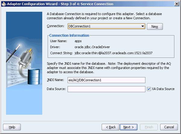
Click New to define a database connection. The Create Database Connection Wizard is displayed.
Note:
You must connect to the database where Oracle Applications is running.Enter the following information in the Type dialog box:
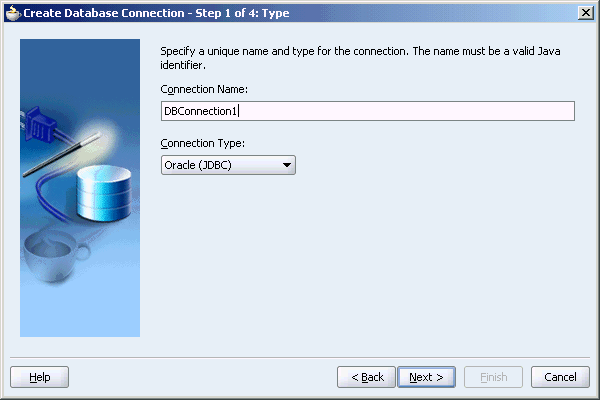
In the Connection Name field, specify a unique name for the database connection. In this example, type DBConnection1.
From the Connection Type box, select Oracle (JDBC).
Figure 3-7 shows the Type dialog box.
Figure 3-7 Specifying the Connection Name and Type of Connection
Click Next. The Authentication dialog box is displayed.
Enter information in the following fields:
In the UserName field, specify a unique name for the database connection. In this example, type scott.
In the Password field, specify a password for the database connection. In this example, type tiger.
Leave the Role field blank.
Select Deploy Password.
Click Next. The Connection dialog box is displayed.
Enter information in the following fields:
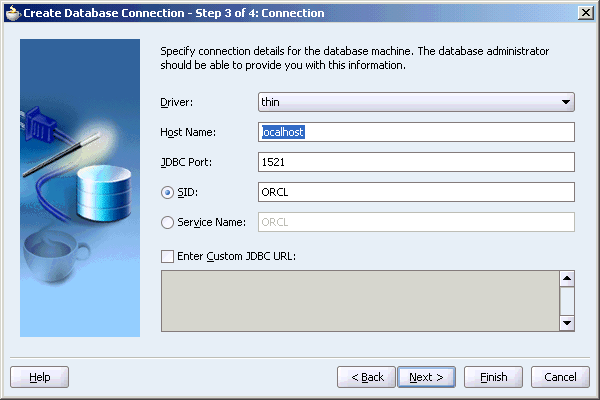
From the Driver list, select Thin.
In the Host Name field, retain the default value, localhost.
In the JDBC Port field, specify the port number for the database connection. In this example, type 1521.
In the SID field, specify a unique SID value for the database connection. In this example, type ORCL.
Figure 3-8 shows the Connection dialog box.
Figure 3-8 Specifying the New Database Connection Information
Click Next. The Test dialog box is displayed.
Click Test Connection to determine whether the specified information establishes a connection with the database.
Click Next. The Service Connection dialog box is displayed, providing a summary of the database connection.
Click Finish to complete the process of creating a new database connection.
Click Next in the Service Connection dialog box.
The Operation dialog box is displayed.
Select Enqueue, to send messages to a queue, or Dequeue, to receive messages from a queue. In this example, select Enqueue, as show in Figure 3-9, and then click Next.
The Queue Name dialog box is displayed, as shown in Figure 3-10.
Select a database schema from the drop-down list, or click Browse to browse for the schema. In this example, click Browse.
The Select Queue dialog box is displayed.
Select the required queue, and then click Ok. In this example, click Customer_In_Queue.
Once you have selected the database schema, click Next.
The Queue Parameters dialog box is displayed, as shown in Figure 3-11.
Figure 3-11 The Queue Parameters Dialog Box
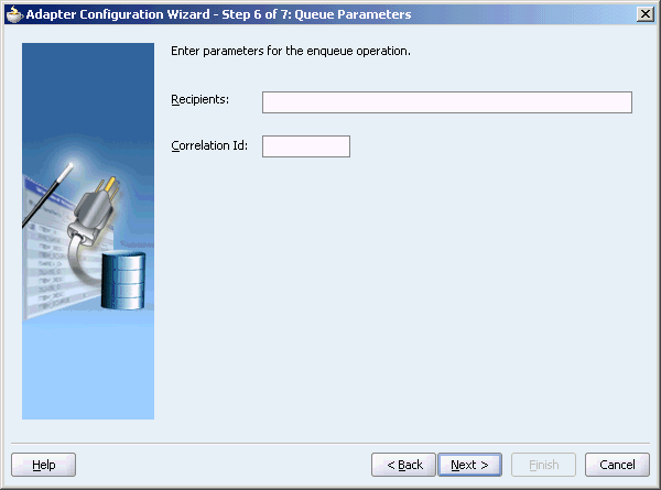
Enter values for the parameters, and then click Next.
Recipients: Enter the consumer name or names separated by commas that are the intended recipients for the messages enqueued by the adapter. The message remains in the queue until all recipients have dequeued the message. If the Recipients field is left empty, then all currently active consumers are recipients. This field can be overridden on a per message basis by setting the RecipientList field described in Table 3-1 in the outbound header.
Correlation ID: Enter an optional correlation ID from 1 to 30 characters in length. This is used to identify messages that can be retrieved at a later time by a dequeue activity using the same correlation ID.
The value to enter is agreed upon between the enqueuing sender and the dequeuing receiver for asynchronous conversations. The correlation ID maps to an AQ header. Correlation IDs in the inbound direction enable you to be selective about the message to dequeue. This field is optional. If you do not enter a value, all messages in the queue are processed.
If you enter a value for the Correlation ID in the outbound direction, all outbound messages have the correct ID set to the value entered. You can override this value on a per message basis in the correlation field of the outbound header.
The Object Payload dialog box is displayed, as shown in Figure 3-12.
Figure 3-12 The Object Payload Dialog Box
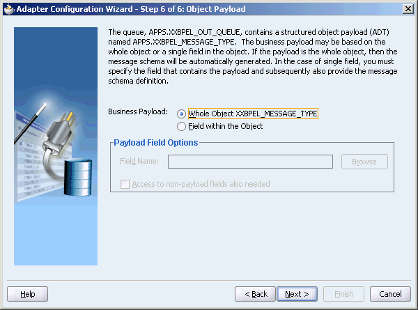
Select the business payload: either the entire object, or just one field within the object. In this example, select Field within the Object.
If you select Whole Object CUSTOMER_TYPE, click Next and go to Step 26. The message schema is automatically generated.
If you select Field within the Object, the business payload is contained in a single field in the object. Specify the correct field name, either by entering the name or by browsing for it using the Browse button. The field containing the payload you select must be a CLOB, BLOB, or VARCHAR2.
The Access to non-payload fields also needed check box is available as an option. Select this check box if you need to specify additional information in a header field that is separate from the object payload. This selection generates the additional header schema but does not automatically create the header variable. Header variable is an optional field used to pass the header to and from the partnerlink. This header variable is created in the adapter tab of corresponding receive or invoke activity. See section Header Variables in JDeveloper BPEL Designer for more information.
For example, your payload may be a JPG image. You may want to specify a person's name in the nonpayload field. This selection generates an additional header schema file (object_name.xsd, where object_name is the structured payload object used by the queue). Using this information is discussed in more detail in Rule-Based Subscription for Multiconsumer Queues.
Under Payload Field Options, enter a file name or click Browse. In this example, click Browse.
The Select Payload Field dialog box is displayed, as shown in Figure 3-13.
Figure 3-13 The Select Payload Field Dialog Box
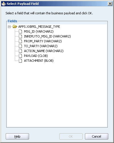
Select TO_PARTY from the list of payload fields, and then click OK.
Click Next.
The Messages dialog box is displayed, as shown in Figure 3-14.
The Message dialog box has the following options:
Native format translation is not required (Schema is Opaque): Select this option if you do not want to specify a schema. Selecting this option disables all the other fields under Message Schema.
Define Schema for Native Format: Click this to start the Native Format Builder wizard, which guides you through the process of defining the native format.
Schema Location: You can enter the path for the schema file URL or click Browse to browse for the path.
In this example, click Browse to browse for the schema file URL.
The Type Chooser dialog box is displayed, as shown in Figure 3-15.
Select BPELProcessProcessRequest from the list, and then click OK.
The Messages window reappears, with the Schema Location and Schema Element fields completed.
Click Next.
The Finish screen is displayed, as shown in Figure 3-16. This dialog box shows the path and name of the adapter file that the wizard creates.
In the Finish window, click Finish.
The Create Partner Link dialog box is displayed, with the fields filled up, as shown in Figure 3-17.
Figure 3-17 The Create Partner Link Dialog Box
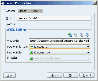
Click OK.
The adapter service generates a WSDL file to serve as the defined adapter interface. This section contains explanation about each code segment in the WSDL file created by the preceding example:
This part of the code segment defines the name of the adapter, and the locations of various necessary schemas and other definition files.
<definitions     name="CustomerDetails1"
     targetNamespace="http://xmlns.oracle.com/pcbpel/adapter/aq/CustomerDetails/"
     xmlns="http://schemas.xmlsoap.org/wsdl/"
     xmlns:tns="http://xmlns.oracle.com/pcbpel/adapter/aq/CustomerDetails/"
     xmlns:plt="http://schemas.xmlsoap.org/ws/2003/05/partner-link/"
     xmlns:jca="http://xmlns.oracle.com/pcbpel/wsdl/jca/"
     xmlns:imp1="http://xmlns.oracle.com/BPELProcess"
     xmlns:hdr="http://xmlns.oracle.com/pcbpel/adapter/aq/outbound/"
    >
The following code segment imports the necessary namespaces:
<import namespace="http://xmlns.oracle.com/pcbpel/adapter/aq/outbound/" location="aqAdapterOutboundHeader.wsdl"/>
    <import namespace="http://xmlns.oracle.com/BPELProcess" location="bpelprocess.wsdl"/>
The following code segment defines the message name and port type for the partner link:
<message name="BPELProcessProcessRequest_msg">
        <part name="BPELProcessProcessRequest" element="imp1:BPELProcessProcessRequest"/>
    </message>
    <portType name="Enqueue_ptt">
        <operation name="Enqueue">
            <input message="tns:BPELProcessProcessRequest_msg"/>
        </operation>
    </portType>
The following code segment defines the necessary bindings for the enqueue operation and the target queue, and identifies the message header:
<binding name="Enqueue_binding" type="tns:Enqueue_ptt">
    <jca:binding />
        <operation name="Enqueue">
      <jca:operation
          InteractionSpec="oracle.tip.adapter.aq.outbound.AQEnqueueInteractionSpec"
          QueueName="CUSTOMER_IN_QUEUE"
          ObjectFieldName="CONTACTS.EMAIL"
          OpaqueSchema="false" >
      </jca:operation>
      <input>
        <jca:header message="hdr:Header" part="Header"/>
      </input>
        </operation>
    </binding>
    <service name="AQ_Example">
        <port name="Enqueue_pt" binding="tns:Enqueue_binding">
This part defines the database connection, the connection factory (as defined in the oc4j-ra.xml file), and the name and role of the partnerLinkType and portType.
<!--Your runtime connection is declared in
J2EE_HOME/application-deployments/default/AqAdapter/oc4j-ra.xml
These mcf properties here are from your design time connection and
save you from having to edit that file and restart the application server
if eis/AQ/DBConnection1 is missing.
These mcf properties are safe to remove.-->
      <jca:address location="eis/AQ/DBConnection1"
UIConnectionName="DBConnection1"
          ManagedConnectionFactory="oracle.tip.adapter.aq.AQManagedConnectionFactory"

mcf.ConnectionString="jdbc:oracle:thin:@144.25.143.7:1521:shashipc"
          mcf.UserName="apps"           mcf.Password="53CB0F044A0D3DD2C063679F18F89870" />         </port>    </service>  <plt:partnerLinkType name="Enqueue_plt" >    <plt:role name="Enqueue_role" >      <plt:portType name="tns:Enqueue_ptt" />    </plt:role>  </plt:partnerLinkType></definitions>
The Adapter Configuration Wizard walkthrough shows how to enqueue one field in an object. To enqueue or dequeue the entire object as the payload, do the following:
Select Enqueue or Dequeue in Step 18.
Select Whole Object CUSTOMER_TYPE in Step 23, and skip to Step 29.
The Adapter Configuration Wizard walkthrough provided an enqueue operation example. For a dequeue operation, the resulting WSDL file differs by including dequeue information instead of enqueue information, and by lacking an ObjectFieldName in the jca:Operation section of the code. See the following code sample for a dequeue operation and compare it to the WSDL file from the general walkthrough to see these differences:
<portType name="Dequeue_ptt">
        <operation name="Dequeue">
            <input message="tns:CUSTOMER_TYPE_msg"/>
        </operation>
    </portType>
    <binding name="Dequeue_binding" type="tns:Dequeue_ptt">
    <pc:inbound_binding />
        <operation name="Dequeue">
      <jca:operation
          ActivationSpec="oracle.tip.adapter.aq.inbound.AQDequeueActivationSpec"
          QueueName="CUSTOMER_OUT_QUEUE
          OpaqueSchema="false" >
      </jca:operation>
      <input>
        <jca:header message="hdr:Header" part="Header"/>
      </input>
        </operation>
The walkthrough is an example of enqueuing one field or column within an object payload. To create an adapter that dequeues the one field in an object, the steps are the same, except that in Step 18, select Dequeue.
The following segment of the generated WSDL file specifies that one field, in this case CONTACTS.EMAIL, is dequeued.
<jca:operation
          ActivationSpec="oracle.tip.adapter.aq.inbound.AQDequeueActivationSpec"
          QueueName="CUSTOMER_IN_QUEUE"
          ObjectFieldName="CONTACTS.EMAIL"
          OpaqueSchema="true" >
      </jca:operation>
If you want to process large numbers of messages with the AQ adapter, ensure that you set the cacheWSIFOperation property to true in the bpel.xml file:
<BPELSuitcase>
 <BPELProcess id="HelloWorld" src="HelloWorld.bpel">
    <partnerLinkBindings>
       <partnerLinkBinding name="Dequeue">
          <property name="wsdlLocation">fileService.wsdl</property>
       </partnerLinkBinding>
       <partnerLinkBinding name="Enqueue">
          <property name="wsdlLocation">fileWriteService.wsdl</property>
          *<property name="cacheWSIFOperation">true</property>*
       </partnerLinkBinding>
    </partnerLinkBindings>
Set this property through the Property tab of the Create Partner Link or Edit Partner Link window for the partner link.
Perform the following steps to set up an adapter that dequeues messages with a certain correlation ID only.
The adapter dequeues messages enqueued with that same correlation ID only.
The resulting WSDL file contains the correlation ID:
<jca:operation
   ActivationSpec="oracle.tip.adapter.aq.inbound.AQDequeueActivationSpec"
   QueueName="CUSTOMER_OUT_QUEUE"
   Correlation="147"
   OpaqueSchema="false" >
</jca:operation>
Multisubscriber queues are accessible by multiple users, and sometimes those users are only concerned with certain types of messages within the queue. For example, you may have a multiuser queue for loan applications where loans below $100,000 can be approved by regular loan-approval staff, whereas loans over $100,000 must be approved by a supervisor. In this case, the BPEL process can use one adapter to enqueue loan applications for big loans for supervisors, and another adapter to enqueue loan applications for smaller loans for regular staff in the same multisubscriber queue.
Specify an adapter that enqueues to a multisubscriber queue, and include queue parameters in the Recipients field and the Correlation ID field.
In step 22, specify Bob in the Recipients field.
The following code is from a WSDL file generated by defining an AQ adapter that enqueues with a recipient list of Bob:
<jca:operation
         InteractionSpec="oracle.tip.adapter.aq.outbound.AQEnqueueInteractionSpec"
          QueueName="IP_IN_QUEUE"
          DatabaseSchema="SCOTT"
          ObjectFieldName="PAYLOAD"
          PayloadHeaderRequired="true"
          RecipientList="Bob"
          OpaqueSchema="true" >
      </jca:operation>
When dequeuing from a multisubscriber queue, the Queue Parameters window is displayed.
The Consumer field is where you specify the consumer name, or the name of the queue subscriber. This must match the Recipient entry on the enqueue process for the message to be dequeued. When subscribing to a multiconsumer queue, this field is required.
The following code is from a WSDL file generated by defining an AQ adapter with a consumer name:
<jca:operation
          ActivationSpec="oracle.tip.adapter.aq.inbound.AQDequeueActivationSpec"
          QueueName="IP_IN_QUEUE"
          DatabaseSchema="SCOTT"
          ObjectFieldName="PAYLOAD"
          PayloadHeaderRequired="true"
          Consumer="Bob"
          OpaqueSchema="true" >
      </jca:operation>
      <input>
        <jca:header message="tns:Header_msg" part="Header"/>
      </input>
        </operation>
The Message Selector Rule field enables you to enter rules for accepting messages. This is discussed in more detail in the following section.
Correlation Id is a number assigned to a message to identify it to specific dequeuers, as mentioned in Step 22. This differs from a subscription rule in that the queue stores messages with a correlation ID for later use when a subscriber using that correlation ID comes online.
When a dequeue is performed from a multisubscriber queue, it is sometimes necessary to screen the messages and accept only those that meet certain conditions. This condition may concern header information, as in selecting messages of only priority 1, or some aspect of the message payload, as in selecting only loan applications above $100,000.
The Message Selector Rule field appears in Step 22 if the selected queue is multisubscriber. Enter a subscription rule in the form of a Boolean expression using syntax similar to a SQL WHERE clause, such as priority = 1, or TAB.USER_DATA.amount > 1000. The adapter only dequeues messages for which this Boolean expression is true.
In Step 23, Access to non-payload fields also needed must be checked in order to access header information.
When this field is checked, the generated WSDL has additional code in the type section:
<complexType name="HeaderCType" >
       <sequence>
         <!-- static header -->
         <element name="QueueHeader" type="hdr:HeaderType" />
         <!-- payload header -->
         <element name="PayloadHeader" type="obj1:SERVICE_TYPE" />
       </sequence>
     </complexType>
     <element name="Header" type="tns:HeaderCType" />
<element name="Header" type="tns:HeaderCType" />and the message:
   <message name="Header_msg">
       <part name="Header" element="tns:Header"/>
   </message>
Note that PayloadHeader is the type for the whole ADT of the queue. The payload contains only the chosen payload field. If Access to non-payload fields also needed is checked, the PayloadHeader contains the whole ADT (including the payload field, which is also present in the header, but ignored by the adapter).
For working examples of rule-based subscription using header and payload information, go to
Oracle_Home\bpel\samples\tutorials\124.AQAdapter\
RuleBasedSubscription_Header

Oracle_Home\bpel\samples\tutorials\124.AQAdapter\
RuleBasedSubscription_Payload
This section comprises tips that you can use while working with AQ adapter. It includes the following sections:
While defining the connection pool for managed data source, set validate-connection property to true when you use oracle.jdbc.pool.OracleDataSource as connection factory inorder to have OC4J validate the connection before returning it to the adapters, as shown in the following example:
<connection-pool name="AQSAMPLE_POOL1" validate-connection='true'>
    <connection-factory factory-class="oracle.jdbc.pool.OracleDataSource"
      user="AQAMAN"
      password="AQAMAN"
      url="jdbc:oracle:thin:@bstern-sun.us.oracle.com:1521:iasdb" />
  </connection-pool>
  <managed-data-source name="AQSAMPLE_DS1"
            connection-pool-name="AQSAMPLE_POOL1"
        jndi-name="jdbc/aqSample1" tx-level="global"
        manage-local-transactions="false"
      login-timeout="0"/>
When defining an OJMS resource provider, set the following property to true -Doracle.jms.useNativeXA=true at the container level when using the thin driver.
This section comprises the following topics:
The entries included in AQ headers are described in "Dequeue and Enqueue Features". These header entries are available for composing subscription rules.
Header information can also be translated into BPEL variables using the Adapter tab when defining BPEL activities that send or receive messages. This tab enables you to create header variables for use with the adapters.
You create header variables in invoke, receive, reply, and pick - OnMessage branch activities. Information passing through header variables is protocol specific.
Note that header information for messages coming from the AQ adapter is different from header information for corresponding messages flowing into the AQ adapter. You must use headers if you need to get or set any of these protocol-specific properties. The following examples describe when you must use headers:
The AQ adapter enables you to get and set the priority of the message. For example, you want two different flows in your business process: one for high priority flows and one for low priority flows. This is possible if you use the inbound AQ header of the message flowing into the business process. In a similar fashion, you can set the priority of an outbound message through the outbound AQ headers.
In a file propagation scenario, files are being moved from one file system to another using the file adapter. In this case, it is imperative that you maintain file names across the two systems. Use file headers in both directions and set the file name in the outbound file header to use the file name in the inbound file header.
The following example describes how to create a special header variable in a receive activity in the outbound direction for the file adapter. You are not restricted to this direction or adapter type. You can also create this variable in either direction (inbound or outbound) with other adapter types that include headers (AQ, JMS, and FTP).
Click the flashlight icon to display the Variable Chooser window.
Select the second Variables folder, and then click Create to display the Create Variable window.
Enter a unique and recognizable name in the Name field (for this example, Variable_Header).
Select Message Type, and then click the flashlight icon to display the Type Chooser window.
Expand Message Types, then Project WSDL Files, then service_name.wsdl, and then Message Types, where service_name is the name you specified for the service name when you ran the Adapter Configuration Wizard.
A header message named OutboundHeader_msg (or a similar name that includes Header_msg as part of the name) is displayed.
If this name appears here, select it and go to Step 8.
If this name does not appear, perform the following additional steps.
Expand Imported WSDL, then fileAdapterOutboundHeader.wsdl (or a similar name for the direction and adapter type you are using), and then Message Types.
Select OutboundHeader_msg and go to Step 8.
Note:
The name that displays here for the AQ adapter may only be Header. Select this name. This indicates that the header is static, because you did not need to select the Access to non-payload fields check box when configuring the AQ adapter.Click OK to close the Type Chooser window, Create Variable window, and Variable Chooser window.
Complete the setup of the Receive activity.
Open the source view of the BPEL process file to view the header variable you created:
bpelx:headerVariable="Variable_Header"/>
Rejected messages (that is, messages with data errors) can be directed to a rejected messages queue, and can also be logged in a directory on the system for later review.
An example of a rejection handler can be found at
Oracle_Home\bpel\samples\tutorials\124.AQAdapter\
AQMessageRejectionHandler
The readme.txt file in this directory describes a procedure for testing the message rejection handler.
The Dequeue.wsdl file in this directory includes the following code:
<pc:inbound_binding />
        <operation name="Dequeue">
      <jca:operation
          ActivationSpec="oracle.tip.adapter.aq.inbound.AQDequeueActivationSpec"
          QueueName="REJECTION_TEST_IN"
          DatabaseSchema="SCOTT"
          OpaqueSchema="false" >
      </jca:operation>
      <input>
        <jca:header message="hdr:Header" part="Header"/>
      </input>
        </operation>
    </binding>
This part of the code directs the errored message to the REJECTION_TEST_IN queue.
Consider a scenario when an RAC environment has two databases, for example, one is infra1 and the other infra2, and BPEL is using both AQ and DB adapters. Here, the oc4j-ra.xml file uses a jdbc connect string that includes the infra1 db but not infra2. So, when infra1 goes down BPEL will not connect to the db even though infra2 is available.
You must make the following changes in the data-sources.xml file to configure BPEL AQ and DB adapters correctly in this environment:
jdbc:oracle:thin:@(DESCRIPTION=
       (ADDRESS_LIST=(LOAD_BALANCE=on)
          (ADDRESS=(PROTOCOL=tcp)(HOST=hostname1)(PORT=1521))
          (ADDRESS=(PROTOCOL=tcp)(HOST=hostname2)(PORT=1521))
       )
       (CONNECT_DATA=(SERVICE_NAME=orcl))
    )
In this sample, the business process receives a message from the AQAdapter, copies the payload to an outbound message and invokes the AQAdapter with the outbound message.The queues involved are ADT queues. In this scenario, where the user has chosen the use whole ADT as the payload, the AQAadpter wizard has generated the schema in SCOTT_CUSTOMER_TYPE.xsd, according to the queue structure. During runtime, a xml that matches the schema will be created by the adapter for each message.
This section comprises the following topics:
The following prerequisites have to be met before you create the sample service:
Access SCOTT schema in some database.
Find data-sources.xml in
C:\product\10.1.3.1\OracleAS_1\bpel\system\appserver\oc4j\j2ee\home\config\data-sources.xml
Add the following code to data-sources.xml to define the data source for jdbc/aqSample. Note that URL should refer to the endpoint database that we use.
<connection-pool name="aqSample_CONNECTION_POOL">
 <connection-factory factory-class="oracle.jdbc.OracleDriver"
url="jdbc:oracle:thin:scott/tiger@stadd14:1521:db5617"/>
 </connection-pool>
 <managed-data-source name="AQSamplesDataSource"
 connection-pool-name="aqSample_CONNECTION_POOL"  jndi-name="eis/AQ/MyConnection" />
The following are the steps to create a new ESB project:
Open Oracle JDeveloper.
From the File menu, select New.
The New Gallery dialog box is displayed.
Select All Technologies from the Filter By box. This displays a list of available categories.
Expand the General node, and then select Projects.
Select ESB Project from the Items group, as shown in Figure 3-18
Click OK.
The Create ESB Project dialog box is displayed.
In the Project Name field, enter a descriptive name. For example, AQADTForESB.
Click OK.
You have created a new ESB project, AQADTForESB.
The following are the steps to create an inbound AQ adapter service:
Select Adapter Services from the Component Palette, and then drag and drop Database Adapter into the AQADTForESB.esb project.
The Create AQ Adapter Service dialog box is displayed, as shown in Figure 3-19.
Figure 3-19 Creating an Inbound AQ Adapter Service
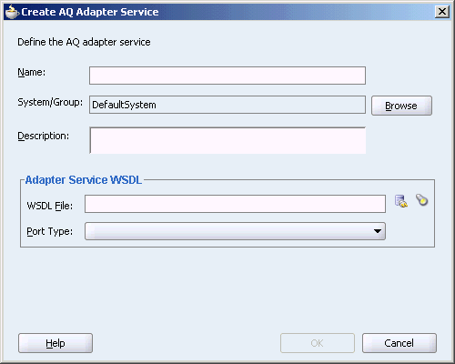
Specify the following information in AQ Adapter Service dialog box:
Name: Type a name for the service. In this example, type Inbound.
System/Group: Retain the default value.
Figure 3-20 shows the AQ Adapter Service dialog box with the Name and System/Group fields, filled up.
Figure 3-20 Defining the AQ Adapter Service
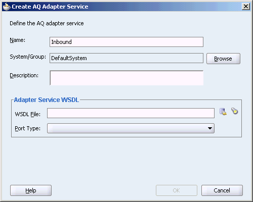
Under Adapter Service WSDL, click the Configure adapter service wsdl icon.
The Adapter Configuration wizard Welcome page is displayed.
Click Next.
The Service Name dialog box is displayed with the Service Name field, filled up.
Retain the service name, and click Next.
The Service Connection dialog box is displayed, as shown in Figure 3-21
Figure 3-21 The Service Connection Dialog Box
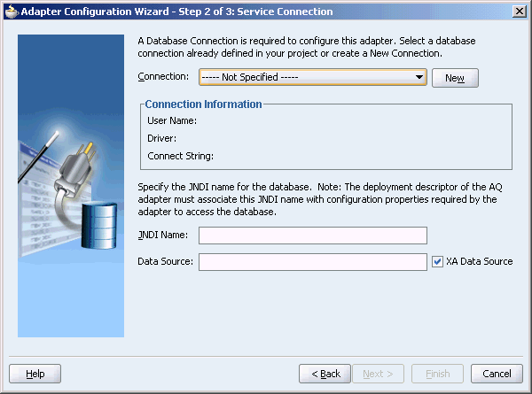
Click New to define a database connection.
The Create Database Connection Wizard Welcome page is displayed.
Click Next.
The Type dialog box is displayed.
Enter the following information in the Type dialog box:
In the Connection Name field, specify a unique name for the database connection. In this example, type MyConnection.
From the Connection Type box, select Oracle (JDBC).
Click Next.
The Authentication dialog box is displayed.
Enter the authentication credentials in the following fields:
In the UserName field, specify a unique name for the database connection. In this example, type scott.
In the Password field, specify a password for the database connection. In this example, type tiger.
Leave the Role field blank.
Select Deploy Password.
Click Next.
The Connection dialog box is displayed.
Enter information in the following fields:
In the Driver list, retain the default value, Thin.
In the Host Name field, retain the default value, localhost.
In the JDBC Port field, specify the port number for the database connection. In this example, type 1521.
In the SID field, specify a unique SID value for the database connection. In this example, type ORCL.
Click Next.
The Test dialog box is displayed.
Click Test Connection to determine whether the specified information establishes a connection with the database.
Click Finish to complete the process of creating a new database connection.
The Service Connection dialog box is displayed, providing a summary of the database connection, as shown in Figure 3-22.
Figure 3-22 The Service Connection Dialog Box
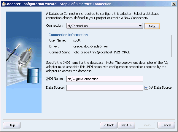
Click Next.
The Operation dialog box is displayed.
Select Dequeue, as shown in Figure 3-23, and then click Next.
The Queue Name dialog box is displayed.
Select a database schema from the drop-down list, or click Browse to browse for the schema. In this example, click Browse.
The Select Queue dialog box is displayed.
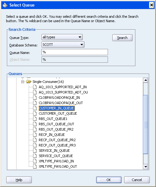
In the Select Queue dialog box, perform the following steps:
For Queue Type, select all types.
For Database Schema, select Scott.
Retail the default values for the other fields.
Under Queues, select CUSTOMER_IN_QUEUES.
Figure 3-24 shows the Select Queue dialog box with all the fields, filled up.
Figure 3-24 Selecting a Queue for the Inbound Operation
Click OK.
The Queue Name dialog box with all the fields populated is displayed, as shown in Figure 3-25.
Click Next.
The Queue Parameters dialog box is displayed.
In the Queue Parameters dialog box, leave the fields empty, and then click Next.
The Object Payload dialog box is displayed, as shown in Figure 3-26.
Figure 3-26 The Object Payload Dialog Box
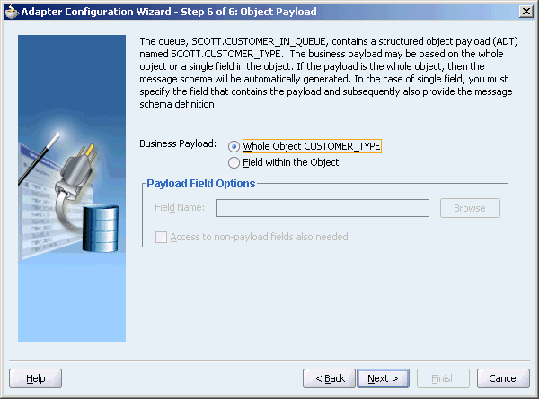
Select a business payload: either the entire object, or just one field within the object. In this example, select Whole Object CUSTOMER_TYPE.
Click Next.
The Finish screen is displayed, as shown in Figure 3-27. This dialog box shows the path and name of the adapter file that the wizard creates.
In the Finish window, click Finish.
The Create AQ Adapter Service dialog box is displayed, with the fields filled up, as shown in Figure 3-17.
Figure 3-28 The Create AQ Adapter Service Dialog Box
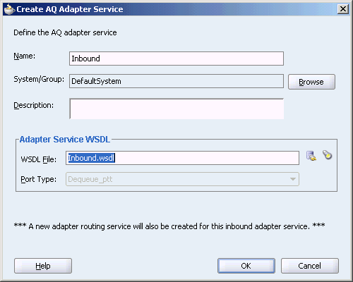
Click OK.
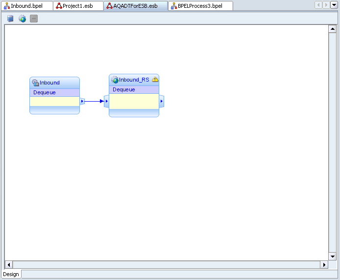
The mid pane of the window will resemble Figure 3-29.
Figure 3-29 Completing the Inbound AQ Adapter Service
The following are the steps to create an outbound AQ adapter service:
Select Adapter Services from the Component Palette, and then drag and drop Database Adapter into the AQADTForESB.esb project.
The Create AQ Adapter Service dialog box is displayed.
Specify the following information in AQ Adapter Service dialog box:
Name: Type a name for the service. In this example, type Outbound.
System/Group: Retain the default value.
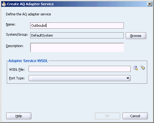
Figure 3-30 shows the AQ Adapter Service dialog box with the Name and System/Group fields, filled up.
Figure 3-30 Defining an Outbound AQ Adapter Service
Under Adapter Service WSDL, click the Configure adapter service wsdl icon.
The Adapter Configuration wizard Welcome page is displayed.
Click Next.
The Service Name dialog box is displayed with the Service Name field, filled up.
Retain the service name, and click Next.
The Service Connection dialog box is displayed.
For Connection, select MyConnection, and then click Next.
The Operation dialog box is displayed.
In the Operation dialog box, select Eequeue, as shown in Figure 3-31.
Click Next.
The Queue Name dialog box is displayed.
In the Queue Name dialog box, select a database schema from the drop-down list, or click Browse to browse for the schema. In this example, click Browse.
The Select Queue dialog box is displayed.
In the Select Queue dialog box, perform the following steps:
For Queue Type, select all types.
For Database Schema, select Scott.
Retail the default values for the other fields.
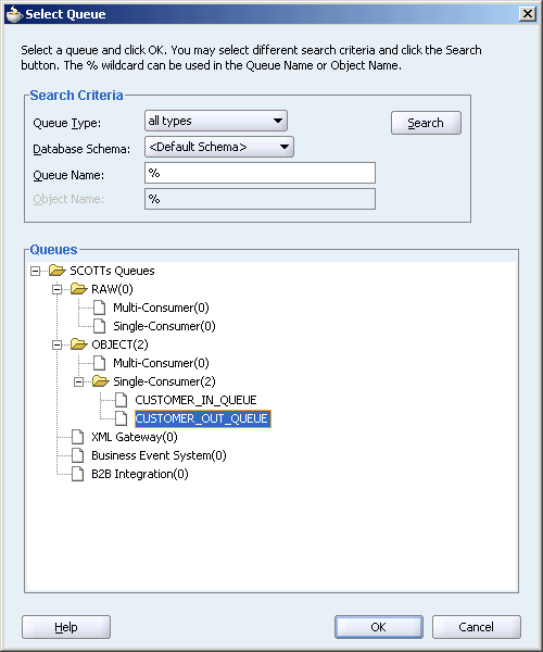
Under Queues, select CUSTOMER_OUT_QUEUES.
Figure 3-32 shows the Select Queue dialog box with all the fields, filled up.
Figure 3-32 Selecting a Queue for the Outbound Operation
Click OK.
The Queue Name dialog box with all the fields populated is displayed, as shown in Figure 3-33.
Click Next.
The Queue Parameters dialog box is displayed.
In the Queue Parameters dialog box, leave the fields empty, and then click Next.
The Object Payload dialog box is displayed.
Select a business payload: either the entire object, or just one field within the object. In this example, select Whole Object CUSTOMER_TYPE.
Click Next.
The Finish screen is displayed, as shown in Figure 3-34. This dialog box shows the path and name of the adapter file that the wizard creates.
In the Finish window, click Finish.
The Create AQ Adapter Service dialog box is displayed, with the fields filled up, as shown in Figure 3-35.
Figure 3-35 The Create AQ Adapter Service Dialog Box
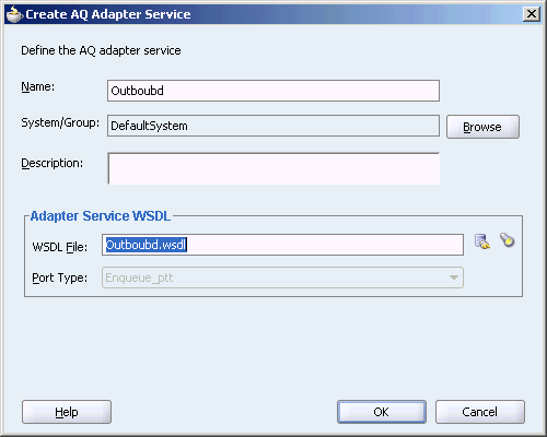
Click OK.
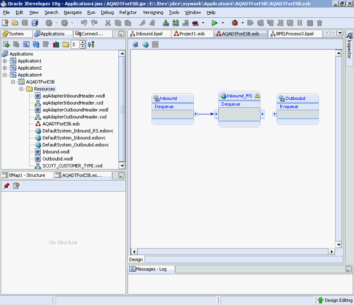
The window will resemble Figure 3-36.
Figure 3-36 Completing the Outbound AQ Adapter Service
The following are the steps to configure the routing service:
Double-click the DefaultSystem_Inbound_RS.esbsvc.
The Routing Service window is displayed in the midpane of the Application window, as shown in Figure 3-37.
Select the Routing Rules tab, and then click on the + icon to add a rule.
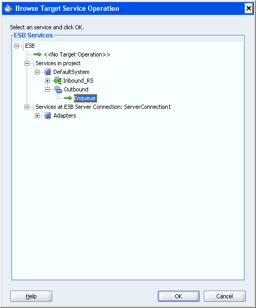
The Browse Target Service Operation dialog box is displayed.
Select the Enqueue service, as shown in Figure 3-38, and then click OK.
Figure 3-38 The Browse Target Service Operation Dialog Box
Click Ok.
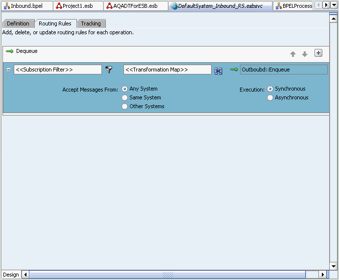
The middle pane of the application window will resemble Figure 3-39.
Figure 3-39 Selecting the Transformation Map
Double-click the Transformation icon, and then click the Select Create New Mapper File icon.
The Request Transformation Map dialog box is displayed, as shown in Figure 3-40.
Figure 3-40 The Request Transformation Map Dialog Box
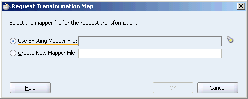
Select the Create New Mapper File option.
Accept the default values, and click OK.
The Transformation window appears, as shown in Figure 3-41.
Select elements on the left-hand side of the mapper and drag it over to the elements on the right-hand side to set the map preferences.
The middle pane of the application window will resemble Figure 3-42.
Save and close the tab for the mapper.
Save and close the tab for the routing service.
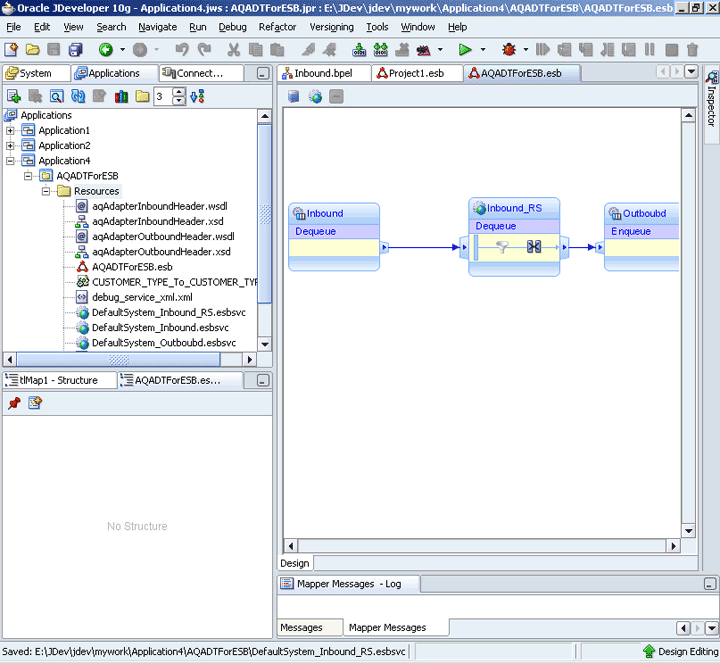
The AQADTForESB project will resemble Figure 3-43.
Figure 3-43 The AQADTForESB Project After Setting Map Preferences
Edit oc4j-ra.xml to reflect your database connection. For example,
eis/DB/MyConnection
oc4j-ra.xml is available at the location where you have installed OracleAS. For example:
C:\product\10.1.3.1\OracleAS_1\j2ee\home\application-deployments\default\AQAdapter\oc4j-ra.xml
Right-click the project, select Register with ESB, and then click LocalESBServer, as shown in Figure 3-44.
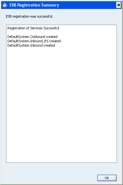
The Success page is displayed, as shown in Figure 3-45.
Figure 3-45 The ESB Registration Summary Page
To check the ESB control, open the ESB Console. For example: http://localhost:8888/esb/esb/EsbConsole.html
Now, your service window will resemble Figure 3-46:
Use the following steps to check execution in the ESB control:
Open the ESB Console.
Click Instances on top-right corner.
Click the green arrow next to Search.
An instance resembling Figure 3-47 is displayed.