|
|
A data service is simply a file containing XQuery functions and supporting structured information. The most basic data service is a physical data service, which models a single physical data source residing in a relational database, Web service, flat file, XML file, or Java function.
Data Services Platform approaches the problem of creating integration architectures by building data services around multiple physical data services. Therefore, in this lesson, you will create data services based on relational data included in the sample PointBase database provided with ALDSP:
After completing this lesson, you will be able to:
A data service is a collection of one or several related query functions. The service typically models a unit of enterprise information, such as customer or product data.
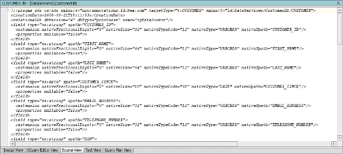
The shape of a data service is defined by an XML type that classifies each data element as a particular form of information, according to its allowable contents and units of data. For example, an xs:string type can be a sequence of alphabetic, numeric, and/or special characters, while an xs:date type can only be numeric characters presented in a YYYY-MM-DD format. ALDSP uses the XML type to model and normalize disparate data into a unified view.
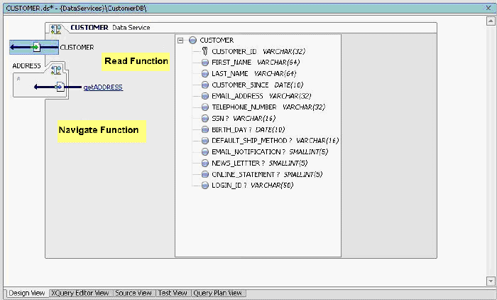
The data service interface consists of public functions that enable client-based consuming applications to retrieve data from the modeled data source.
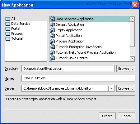
Because a data service is part of a specific ALDSP project, and a project is part of a single WebLogic Workshop application, you will first need to create the application, and then a project, before creating a physical data service. (Alternatively, an existing application could be used; in that case you would simply create a ALDSP project within the application.)
An application, which is deployed as a single unit to an instance of WebLogic Server, is a J2EE enterprise application that ultimately produces a J2EE Enterprise Application Archive (EAR) file. This, in turn, provides you with a multi-user application that is ready for Internet deployment. Except in specific cases, such as accessing remote EJBs or Web services, an application is self-contained. The application's components may reference each other, but may not generally reference components in other applications. An application's components include:
An application should represent a related collection of business solutions. For example, if you are deploying two Web sites — one an e-commerce site and the other a human resources portal for employees — you would probably create separate WebLogic applications for each.
An application is also the top-level unit of work that you manipulate within the WebLogic Workshop environment. Only one application can be active at a time.
| Note: | The sample code used to work on this tutorial uses Evaluation as the application name. Ensure that you name the ALDSP application as Evaluation so that the sample works successfully with your application. |
The components of the application are represented in a hierarchical tree structure in the Application pane. When you first create a Data Services application, the following default components are automatically generated:
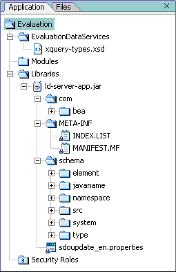
Data Service project. Takes the name of your application (in this case, Evaluation). Within the project folder, there is initially a single component, the xquery-types.xsd file. This file is an XML Schema Definition (XSD) that describes the contents, semantics, and structure of the project.
| Note: | Initially, the Libraries folder is empty. The ld-server-app.jar file is imported only after you build the Evaluation project. |
Figure 2-2 displays the default folders created for the Evaluation application.
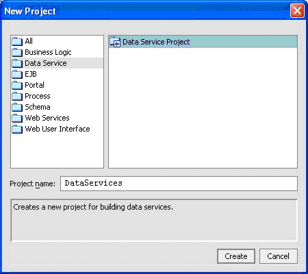
A project groups related files—data services, models, and metadata—within an application. Each application can support multiple projects. As you develop the application, you may want to create new projects for the following reasons:
To separate unrelated functionality. Each project should contain closely-related components. For example, if you want to create one or more data services that expose order status to your customers, and also one or more Web services that expose inventory status to your suppliers, you would probably organize these two sets of unrelated Web services into two projects.
To control build units. Each project produces a particular type of file when the project is built. For example, a Java project produces a JAR file. If you want to reuse the Java classes, you would segregate the Java classes into a separate project, and then reference the resulting JAR file from other projects in your application.
Although a default Data Services project is created when you create a new Data Service application, for this tutorial you will create a new project.
The components of your new Data Service project are represented in a hierarchical tree structure in the Application pane. At present, there is only one component in the project, the xquery-types .xsd file. This file is an XML schema definition that describes the contents, semantics, and structure of the project.
Folders let you logically group different data services, and their associated files, within a single project. For example, if you had three data sources — one relational database containing tables for customer-oriented information and two Web services providing credit rating and information — you would probably want to create two folders, one for the database and one for the Web services.
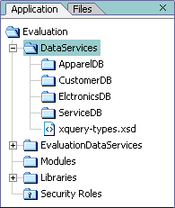
After adding these four folders, your DataServices project folder should look similar to Figure 2-4.
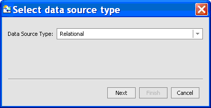
When you installed DSP, several sample data sources were also installed. One such sample data source is the Avitek RTL PointBase database. It contains a number of relational database schemas that provide the metadata needed to build your physical data services, including:
A physical data service, which models physical data existing somewhere in your enterprise, is automatically generated when you import relational source metadata. Each generated physical data service represents a single data source that can be integrated with other physical or logical data services.
| Note: | WebLogic Server must be running. If it is not already running, start the server (see 1.3 Starting WebLogic Server) before you begin this exercise. |
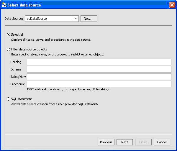
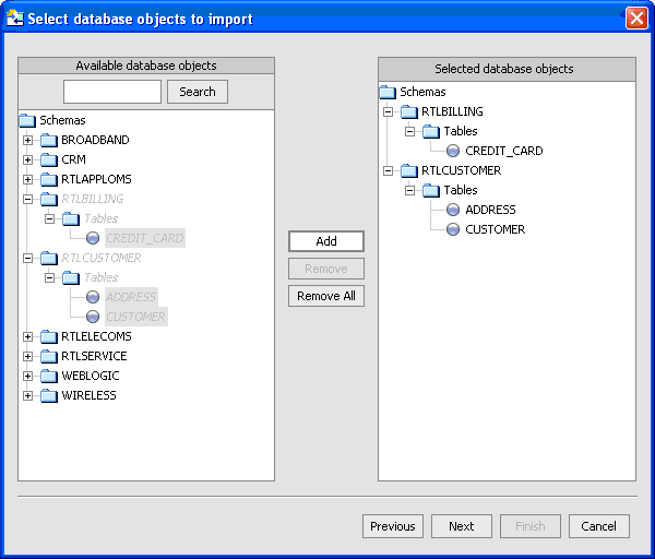
WebLogic Server fetches the specified data, and then displays the Select Database Objects to Import dialog box. The source metadata for each selected object will be used to generate a physical data service.
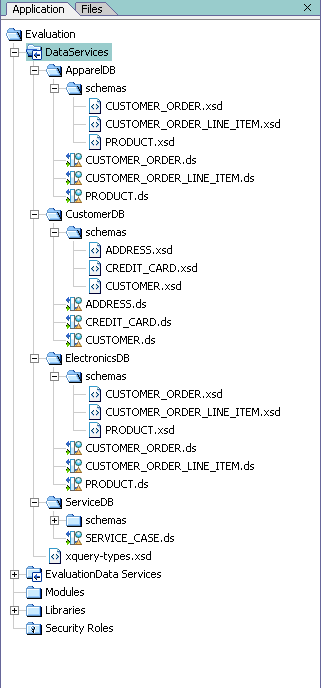
The Application pane should appear similar to Figure 2-10. If you expand a data service's schema folder, you will see XSD files for each data service generated from the underlying data source.
Building a project simply means that the project's source code is compiled into machine-readable instructions. Each project produces a particular type of file when the project is built. For example, a Java project produces a JAR file.
 Windows Build or press Alt+5.)
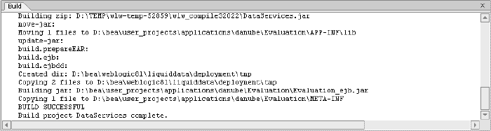
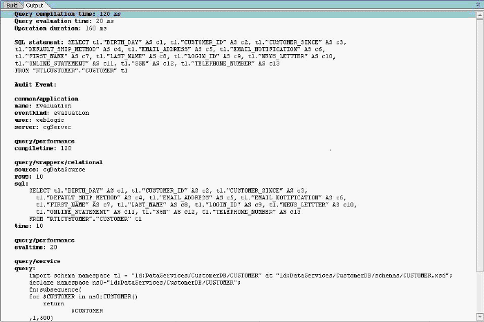
Figure 2-12 displays the complete Build information for the DataServices project.
A physical data service is automatically generated when you import source metadata and build the associated project. Each generated physical data service represents a single data source that can be integrated with other physical or logical data services.
When ALDSP generates a physical data service, it also generates XML data types, an XML Schema Definition (.xsd file), default query and navigation functions, and pragma information.
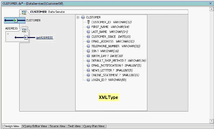
An XML type, which derives from the data service's XML Schema Definition (XSD), is a structured XML document that classifies each element within the data service as a particular form of information, according to its allowable contents and units of data. For example, the XML type for the CUSTOMER data service is CUSTOMER, whose elements include:
Multiple data services can use a single XML type. ALDSP uses the XML type as the default superset of data elements that will be returned by a set of queries. This superset XML type, known as the Return type, models and normalizes data retrieved from the underlying data source, thereby transforming disparate data into a unified view.
| Note: | The data service automatically opens in the View workspace last used; if Design View is not currently open, click the Design View tab. |
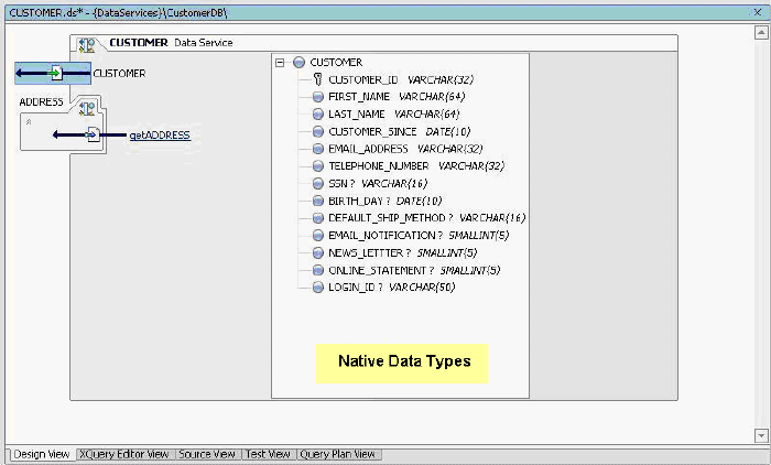
A Native Data Type classifies each data element according to the definitions specified in the underlying data source. For relational data sources, ALDSP generates Native Data Type definitions based on the underlying database's table structure and column data definitions.
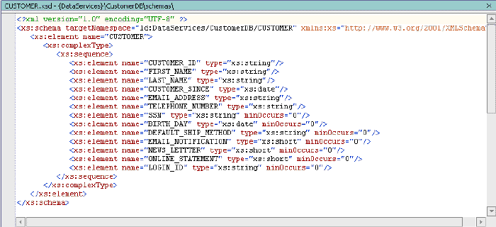
An XML Schema Definition file (.xsd) corresponds exactly to the XML type of a data service. It defines the structure and content of an XML document, such as the XML type document. In other words, it defines the vocabulary, rules, and conventions for representing information in a system.
An .xsd file is organized as a flat catalog of complex elements, any attributes, and any child elements. For physical data services, ALDSP automatically generates a .xsd file from underlying data when the underlying data source's metadata is imported. Generated .xsd files are placed in the appropriate data service's schema directory.
| Note: | For logical data services, you must create a schema. You can use XQuery Editor View, discussed in Creating a Logical Data Service, to create such schemas (XSD files). |
| Note: | Clicking the large red X will close WebLogic Workshop. |
The data service interface consists of public functions of the data service, which can be of several types:
In addition to public functions, a data service can include private functions and side effect functions. Private functions are only used within the data service. They generally contain common processing logic that can be used by more than one data service function. Side effect functions can be invoked from the client side. For example, a side effect function can contain code to update a non-RDBMS data source, such as xml, flat files, and Web services, and clients can invoke this function to perform updates. (For more information, see the Data Service Developer's Guide.)
Metadata is simply information about the structure of data; it provides facts about the data service's data, format, meaning, and lineage. For example, a list of tables and columns within a database is metadata. ALDSP uses metadata to describe a data service: what information is provided by the data service and the information's lineage (that is, the source for the information.)
In addition to documenting data services for potential consumers, metadata helps you determine what data services are affected when inevitable changes occur in the underlying data source layer. Of course in the case of physical data services, the metadata primarily describes metadata extracted from the physical data source.
Metadata information is contained in the data service's META-INF folder. Normally you should not need to refer to the contents of this folder.
| Note: | Before you test any function or data service, you should ideally clean and redeploy the application, so that the data is updated on the WebLogic server also. |
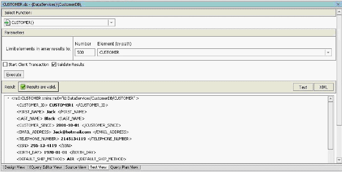
Testing a data service's functionality within Test View lets you determine whether the data service is able to return the expected data results.
| Note: | At times the WebLogic server may not get updated automatically. In that case, you may get some validation errors when you execute the function. To fix this, try cleaning and redeploying the application. |
Each element defined by the XML type returns specific data retrieved from the RTLCUSTOMER database. For example, the <FIRST_NAME> element returns "Jack" as an xs:string, while the <CUSTOMER_SINCE> element returns "2001-10-01" as an xs:date.
| Notes: |
Test View, click Execute again. Windows Output). | Note: | You can use the Output window to verify that each element in the data service is pulling data from the correct data source. In this example, the return results are pulled from the RTLCUSTOMER database, CUSTOMER table 1, and a specific column (c1, c2, c3, and so on) for each element. |
In this lesson, you learned how to:


|