


|
This section discusses the service composition capabilities of AquaLogic Service Bus. It highlights operational features that enable service configuration and key concepts associated with message structures and message flow modeling. It is intended for integration-focused IT architects responsible for messaging and service oriented architectures (SOA) and service modelers or designers. This section includes the following topics:
AquaLogic Service Bus mediates service request and response messages between disparate heterogenous service endpoints and intelligently routes messages between them. Content-based routing is a mediation capability supported by AquaLogic Service Bus based on conditional message processing and transformation capabilities. This routing capability allows loose coupling of SOA endpoints and is particularly useful and allows service enrichment and reuse by combining transformation and routing functions.
AquaLogic Service Bus performs dynamic message routing based on a message content, for cases when services or responses need to be directed to multiple destination service and in scenarios where different versions of a service have to be provisioned based upon business service requests. Dynamic routing is useful when business requirements dictate that certain conditions of a request define where it should be processed. For example, a financial institution’s request for a credit report on a customer may use any of several credit services based on where the customer or organization resides.
In dynamic routing, a message is analyzed using conditional checks in conditional branching statements, to retrieve the value of a data element or multiple data elements that determine the routing logic. Different business service destinations are assigned to different value combinations resulting from this conditional check. The message is dynamically routed to one of multiple destination business services based on the data element value. Transformations may be applied to the response message going to one or more of these destinations depending on business-service requirements.
AquaLogic Service Bus routes message between business services (such as enterprise services and databases) and service clients (such as presentation applications or other business services) through proxy services. The following sections detail the AquaLogic Service Bus features available for designing and implementing proxy services that support content-based routing.
Proxy services are definitions of generic intermediary Web services, that are hosted locally on AquaLogic Service Bus. A proxy service communicates with other services in the IT infrastructure through interfaces, which may or may not be identical to that of a service provider or service consumer business service. Proxy services can route messages to multiple business services, using their configured independent interfaces. For more information on proxy services, see Proxy Services in Using the AquaLogic Service Bus Console.
Proxy services can be defined and configured using the AquaLogic Service Bus Console. They are configured by specifying its interface, type of transport it uses, and its associated message processing logic. Message handling capabilities of a proxy service are implemented with message flow definitions. For more information on message flow definitions, see Modeling Message Flow in AquaLogic Service Bus in BEA AquaLogic Service Bus User Guide.
When a proxy service interfaces with multiple business services, a message flow definition is configured to route a message to the appropriate business service and map the message data into the format required by the business service’s interface. For more information about the structure of proxy services, see Message Flow Modeling.
Business services are AquaLogic Service Bus definitions of the enterprise services that exchange messages during business processes. A business service and its interface can be defined and configured using the AquaLogic Service Bus Console. A business service is configured by specifying its interface, type of transport it uses, its security requirements, and other characteristics. A business service definition is similar to that of a proxy service, but it does not have a pipeline. For information on how to configure a business service using the AquaLogic Service Bus Console, see “Adding a Business Service” in Business Services in the Using the AquaLogic Service Bus Console.
A service account can be created to provide authentication when connecting to a business service. It acts as an alias resource for the required username and password pair. For more information, see Business Services and Service Accounts in Using the AquaLogic Service Bus Console. WebLogic Server can be used to directly manage security credentials for a business service requiring credential-level validation. For more information on business service security considerations, see the AquaLogic Service Bus Security Guide.
AquaLogic Service Bus provides the ability to create a generic proxy service that accepts any SOAP or XML messages. This helps masks the underlying complexity of protocol specifications from the service consumer. The proxy service can be configured to analyze SOAP or XML messages that it receives and dynamically route the message using content-based routing logic. Generating proxy services from a generic template, also promotes dynamic protocol switching, which allows end-point protocol selection to be made at run-time.
Message flows are definitions used for implementing proxy services within AquaLogic Service Bus. Message flow modeling involves configuration of message processing logic in proxy service message flow definitions. This logic includes such activities as transformation, publishing, reporting and exception management. Each of these activities are configured as individual actions within the message flow. The graphical modeling tools available in the AquaLogic Service Bus Console, can be used to perform message modeling.
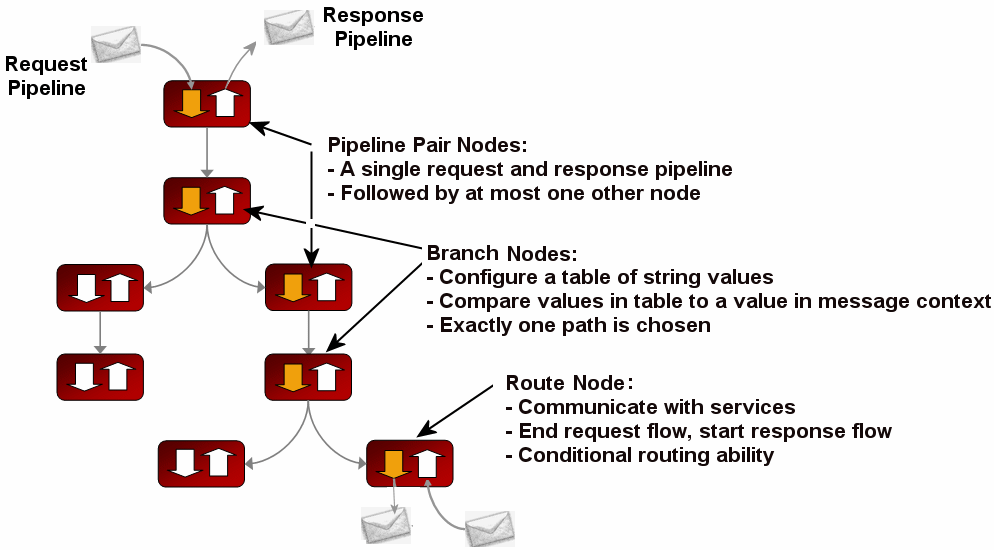
AquaLogic Service Bus proxy service implementations are defined in message flow definitions using components such as pipelines, branch nodes, and route nodes. The following figure shows a high-level view of the message flow definition components.
For more information on message flow modeling, see Modeling Message Flow in AquaLogic Service Bus in the AquaLogic Service Bus User Guide.
A pipeline is a named sequence of stages, representing a non-branching one-way processing path. It is used to specify the message flow for service requests and responses. Pipelines fall into one of the following three categories:
A single service level request pipeline in a stage might optionally branch out into operational pipelines (at most one per operation, and optionally a default operational pipeline). The operation is determined by user-selected criteria. The response processing starts with the relevant operation pipeline which then merges into a single service-level response pipeline. The following figure shows an example of operation pipelines in a proxy service.
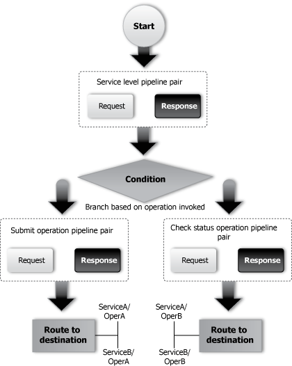
For one-way operations, the response pipeline is executed with an empty message. This permits a response to be constructed for the proxy service, enabling bridging between request/response and one-way operations. The bridging mechanism means that proxy service input can be one-way while its output is request/response or vice versa. The proxy service either absorbs the response from the invoked service or generates one for the client. Actions in the response flow may also be used to do post processing on the message after it has been routed to the business service or the proxy service.
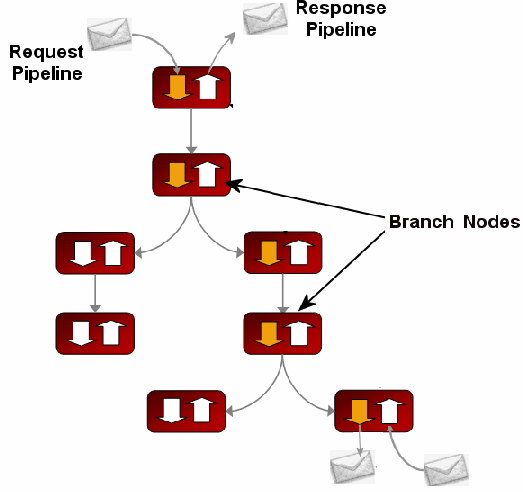
A branch node allows processing to proceed down exactly one of several possible paths. Branching is driven by a simple lookup table with each branch tagged with a simple but unique string value.A variable in the message context is designated as the lookup variable for that node, and its value is used to determine which branch to follow. If no branch matches the value of the lookup variable, then a default branch is followed. The value of the lookup variable must be set before reaching the branch node. This approach ensures that exceptions do not occur within the branch node itself. A branch node may have several descendants in the message flow tree: one for each branch including the default branch.
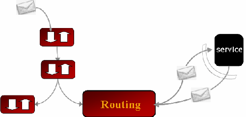
The route node is used to perform request and response communication with another service. It represents the boundary between request and response processing for the proxy service, and therefore, cannot have any descendants in the message flow tree. When the route node dispatches a request message, request processing is considered finished. When the route node receives a response message, response processing begins.
The route node is very flexible in its specification and supports conditional routing as well as outbound and response transformations. It allows if structures and case structures to be combined (and nested) to define a single endpoint and operation to route the message. For information about how to configure route nodes, see “Adding a Route Node” in
Proxy Services in Using the AquaLogic Service Bus Console.
Echo node is a route node that routes (or echoes) a message from the end of the request pipeline to the start of the response pipeline. The message is not routed from the proxy service to another service, but remains within the proxy service.
Pipeline logic occurs in pairs of definitions consisting of a request pipeline definition and a response pipeline definition. The request pipeline definition specifies the actions that AquaLogic Service Bus performs on request messages to the proxy service before invoking a business service or another proxy service. The response pipeline definition specifies the processing that AquaLogic Service Bus performs on responses from the service invoked by the proxy service before the proxy service returns a response. Routing is performed by a route node at the end of the message flow.
To create the request and response paths, request and response pipelines are paired together and organized into a single-rooted tree structure. A branch node allows these pipeline pairs to be executed conditionally, and route nodes at the ends of the branches perform the request and response dispatching. A pipeline tree chains together instances of the following top-level components - pipeline pair node, branch node, route node or echo node.
A pipeline pair node ties together a single request and a single response pipeline into one top-level element. Only the request pipeline is executed during request processing, and only the response pipeline is executed when reversing the path for response processing.
Each pipeline is a sequence of stages that contain actions. An action is a user-configured processing step such as transformation or publishing. Messages fed into the message flow are accompanied by a set of message context variables that contain the message contents and can be accessed or modified by actions in the pipeline stages.
The following table describes the actions supported in a AquaLogic Service Bus pipeline stages, branch and route nodes.
Action1
|
|
1For information about actions, including how to configure them, see Proxy Services: Actions in Using the AquaLogic Service Bus Console. |
Since message flow is typically used with WSDL-based services, operation-specific processing must frequently be performed. Rather than requiring manual configurations of a branching node based on operation, the AquaLogic Service Bus provides a zero-configuration branching node that branches automatically. In other words, if no operational branching is configured for a service end point, message processing will automatically branch to the appropriate operation based on the operation specified in the message context.
AquaLogic Service Bus provides a service callout action that offers greater flexibility for more sophisticated message flows. Service Callouts are message processing request actions from one message flow, that invoke other services registered within AquaLogic Service Bus. This action is generally used in response to decisions made in complex dynamic-routing processing, or to perform message enrichment. The service callout action is used inside a message flow routing stage, to call on the destination service to perform some action on the message. The destination service returns a response to the message flow, which gets assigned to a local variable. The variable may be used within the current message flow for conditional branching.
For information about the Service Callout functionality, see "Constructing Service Callout Messages" in Modeling Message Flow in AquaLogic Service Bus in the AquaLogic Service Bus User Guide.
Service callouts allow custom Java code to be invoked from within proxy services. AquaLogic Service Bus supports a Java exit mechanism via a Java Callout action that allows call out to a Plain Old Java Object (POJO). Static methods can be accessed from any POJO. The POJO and its parameters are visible in the AquaLogic Service Bus Console at design time; the parameters can be mapped to message context variables. For information about configuring a Java Callout to a POJO, see Java Callout in Proxy Services: Actions in Using the AquaLogic Service Bus Console.
Transformations are used when disparate message data types exist between source and destination services, requiring data mapping to ensure service compatibility. AquaLogic Service Bus supports data mapping using XQuery and the eXtensible Stylesheet Language Transformation (XSLT) standard. Messages can be transformed in two ways:
Transformations can be created by a developer and imported into BEA AquaLogic Service Bus, or scripted using XQuery in the AquaLogic Service Bus Console. Transformations can occur at different locations depending on the message-flow configuration of the proxy service.
In AquaLogic Service Bus, the Message Flow defines the implementation of a proxy service. You configure AquaLogic Service Bus proxy services in the AquaLogic Service Bus Console, which is described in Using the AquaLogic Service Bus Console.
AquaLogic Service Bus supports data mapping that uses XQuery and the eXtensible Stylesheet Language Transformation (XSLT) standards. XSLT maps describe XML-to-XML mappings, whereas XQuery maps can describe XML-to-XML, XML to non-XML, and non-XML to XML mappings. For more information on transformations, see Performing Transformations in BEA AquaLogic Service Bus User Guide.
For more information, see XQuery Transformations and XSL Transformations in Using the AquaLogic Service Bus Console. For information on using the BEA XQuery Mapper to create XQueries, see Transforming Data Using the XQuery Mapper.
Transformation maps describe the mapping between two incompatible data types. AquaLogic Service Bus supports data mapping using either XQuery or the eXtensible Stylesheet Language Transformation (XSLT) standard. XSLT maps describe XML-to-XML mappings, whereas XQuery maps can describe XML-to-XML, XML to non-XML, and non-XML to XML mappings. In addition, MFL described data is automatically converted to the equivalent XML for transformation with XQuery or XSLT. The resulting XML is automatically converted to MFL if the target service requires it. For more information, see XQuery Transformations and XSL Transformations in Using the AquaLogic Service Bus Console. For information on using the BEA XQuery Mapper to create XQueries, see Transforming Data Using the XQuery Mapper.
Message manipulation is a kind of transformation in which the contents of a message, rather than its whole structure, are manipulated to make the message compatible with the destination service. This is performed by adding, replacing or removing actions to the request or response pipelines of the message flow. The different actions available to transform a message through content manipulation are described in the following table:
Inserts a data element into the message. This insertion may occur anywhere within the message context as specified during configuration. |
|
AquaLogic Service Bus provides robust and flexible error handling for configured services. It can handle errors in the following ways:
AquaLogic Service Bus provides the capability for incoming or outgoing messages to be validated against a WSDL or XML schema with a validation action. This action can occur at any time within the message flow and ensures that the incoming or outgoing message is in the format expected by the destination service’s consumer or provider. Messages that fail validation can log the failure or create an error. In the latter case, an error stage can be used to apply alternative actions.
Message validation can be used for service versioning to validate messages against different versions of a schema or WSDL. This is to ensure the message is routed to the proper version of the service end point, or to check whether transformation must be applied prior to sending the message.
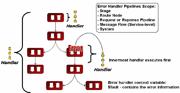
AquaLogic Service Bus provides a mechanism to handle errors by allowing error handlers to be defined. An error handler is a pipeline that allows various actions such as logging, transformation, and publishing to be performed to handle errors appropriately. If an error occurs within a stage a sequence of steps are executed. This sequence of steps constitutes an error pipeline for that stage.
The error pipeline allows you to handle the error in the following ways:
Errors can occur during message flow processing for various reasons. For example, security errors occur if a username is not correctly validated or authorized; transformation errors occur if AquaLogic Service Bus is unable to successfully transform or validate a message; a routing error is raised if a routing service is unavailable, and so on. Typically, these errors originate from a specific stage, route node or from the proxy service, as this is where most of the message flow logic is implemented.
Each stage can have a sequence of steps to execute if an error occurs in that stage. This sequence of steps constitute an error pipeline for that stage. In addition, an error pipeline can be defined for a pipeline (request or response) or for an entire proxy service. The lowest scoped error pipeline that exists is invoked on an error.
The AquaLogic Service Bus Console can be used to track messages to obtain an accurate picture of a message flow. This could enable error visibility; for example, the original reported message could be viewed, indicating it was submitted for processing, and then the subsequent reported error could be viewed, indicating that the message was not processed correctly. This would provide a complete view of both the message flow and error flow.


|