

|
|
|
|
|
|
eLink Adapter for CORBA Configuration
This section contains instructions and information for configuring the eLink Adapter for CORBA to run in the WLE environment.
This section contains the following topics:
eLink Adapter for CORBA Configuration Components
Configuring the eLink Adapter for CORBA is a central task of the administrator. In configuring the adapter, you are defining the services to be made available by the adapter. In addition to adapter specific configuration, you must configure the FML32 fields to be used in a specific domain, define information necessary to boot the application you use, and describe the relationship between the local and remote domains being utilized. All this configuration is accomplished through the use of configuration files you will create, edit and compile. These configuration files work together to configure the eLink Adapter for CORBA. The following architectural diagram provides an overview of the configuration components for the eLink Adapter for CORBA and illustrates how they work together.
Figure 4-1 eLink Adapter for CORBA Configuration Components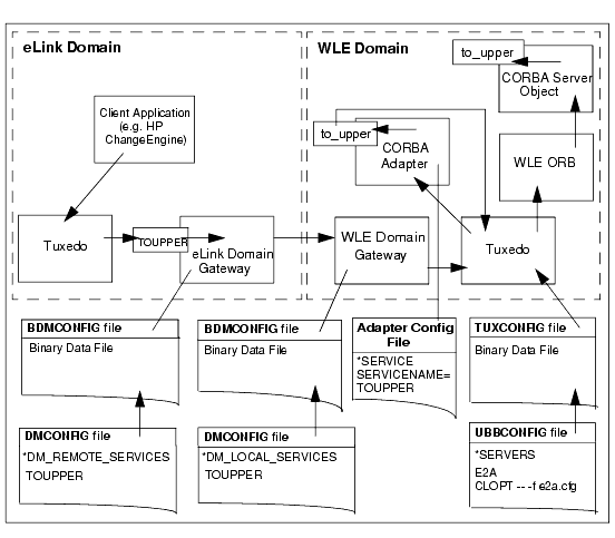
The following files must be modified to configure the eLink Adapter into WebLogic Enterprise CORBA for use with the WebLogic Enterprise product. The order in which each component is described is the same order in which you should configure the eLink Adapter for CORBA.
The eLink Adapter for CORBA adapter configuration file defines each service that will be supported by an instance of the adapter. The file contains information on services to be made available to the eLink Adapter into WebLogic Enterprise CORBA. During initialization, the eLink Adapter into WebLogic Enterprise CORBA server reads the Adapter configuration file specified in the command line option (CLOPT) line in the UBBCONFIG file.
The FML32 Field Table files are used by the eLink Adapter for CORBA and WLE to manage FML32 field definitions. The Field Table file contains definitions of fields that will be used in a specific domain. Field definitions include the name of the FML32 field, a field identifier, and the data type of the field. The FTGEN configuration tool that generates this file uses the adapter configuration file and the Interface Repository as input to create the file. The FTGEN configuration tool also creates a list of fields used by the services listed in the adapter configuration file.
The UBBCONFIG file is an ASCII text version that contains the information necessary to boot the local application (an instance of the eLink Platform). The UBBCONFIG file also contains the name of the server used to advertise services that represent CORBA methods. The UBBCONFIG file is the file from which the TUXCONFIG file is generated.
The TUXCONFIG file is the binary version of the UBBCONFIG file and contains the information used by the tmboot command to start services and initialize the WLE application Bulletin Board in an orderly sequence. The TUXCONFIG file is accessed by all BEA WLE and eLink Platform processes for all configuration information.
The DMCONFIG file describes the relationship between the local domain (the domain in which the DMCONFIG file resides) and the remote domain (any other domain). There is one DMCONFIG file per domain. The DMCONFIG file contains domain information for eLink Platform domains and for WLE domains. How multiple domains are connected and which services they make accessible to each other are defined in a Domains configuration file on each domain. The DMCONFIG file defines the following:
The DMCONFIG file is parsed and loaded into a binary version, called BDMCONFIG, by the dmloadcf utility. The dmadmin command uses BDMCONFIG (or a copy of it) for monitoring the run-time application. One BDMCONFIG file is required on each domain in a multi-domain configuration in which the Domains feature is being used.
eLink Adapter for CORBA Configuration Prerequisites
The following configuration prerequisites must be met prior to beginning the eLink Adapter for CORBA configuration.
Note: The eLink Adapter for CORBA configuration tools and the runtime server all utilize the WLE Interface Repository.
Setting Application Environment Variables
In order to function properly, the various eLink Adapter into WebLogic Enterprise CORBA components require certain environment variables concerning the operating system environment in which the servers reside. The setenv file that installs with your eLink Adapter into WebLogic Enterprise CORBA software is a sample script that sets environment variables.
For multiple-domain configurations, these environment variables must be set for both the local and remote domains. Additionally, if you modify the configuration of your eLink Adapter for CORBA system or the supporting software, you must also update the setenv.sh file to reflect those changes. The setenv.sh file is located in the samples directory, $TUXDIR/eLink/elcorba/samples.
You must set the following environment variables for the application to be configured successfully:
/opt/tuxedo
/work/apps
$APPDIR/tuxconfig
$APPDIR/dmconfig
$TUXDIR/bin
$TUXDIR/lib
Note: The FLDTBLDIR32 and FIELDTBLS32 environment variables are set during the FML32 Field Table file configuration.
The following listing provides an example of the environment variables.
Listing 4-1 Local Environment Variable Example
#!/bin/ksh
export TUXDIR="/opt/tuxedo"
export PATH=$PATH:$TUXDIR/bin
export SHLIB_PATH=$TUXDIR/lib
export TOBJADDR="//dalhp5:2468"
export APPDIR="/work/test/testcorba"
export TUXCONFIG="$APPDIR/tuxconfig"
export FLDTBLDIR32=$APPDIR:$TUXDIR/udataobj
export FIELDTBLS32=adapter.flds,Usysflds
Note: The TUXDIR, APPDIR, and TUXCONFIG variables must agree with their counterpart variables in the MACHINES section of the UBBCONFIG configuration file.
Understanding the Interface Repository
The BEA WebLogic Enterprise Interface Repository contains the interface descriptions of the CORBA objects. The CFGEN and FTGEN configuration tools that install as part of the eLink Adapter for CORBA access the Interface Repository to assist you in configuring the adapter. The Interface Repository also assists in runtime conversion of service calls to CORBA object invocations.
The BEA WebLogic Enterprise Interface Repository is based on the CORBA definition of an Interface Repository. It offers a proper subset of the interfaces defined by CORBA; that is, the APIs that are exposed to programmers are implemented as defined by the Common Object Request Broker: Architecture and Specification Revision 2.2. However, not all interfaces are supported. In general, the interfaces required to read from the Interface Repository are supported, but the interfaces required to write to the Interface Repository are not. Additionally, not all TypeCode interfaces are supported.
The Interface Repository consists of two distinct components; the database and the server. The (TMIFRSVR) server performs operations on the database. The Interface Repository database is created and populated using the idl2ir administrative command. You must use the idl2ir administrative command to populate the Interface Repository database with any objects you plan to utilize using the eLink Adapter into WebLogic Enterprise CORBA. This administrative program is distributed with WLE.
Loading the Interface Repository
To create the Interface Repository and load it with interface definitions, you must use the idl2ir administrative program. If no repository file exists, this command creates it. If a repository file does exist, this command loads the specified interface definitions into it and, in effect, updates the file. When the file is updated, a new Interface Repository database file is created.
The Interface Repository server (TMIFRSVR) must be running in order for the eLink Adapter into WebLogic Enterprise CORBA to work properly. The TMIFRSVR server is included with WLE for accessing the Interface Repository. You can verify TMIFRSVR is running by using the psr command of the tmadmin utility.
The following provides an example of using the idl2ir command to load the Interface Repository.
Listing 4-2 Sample idl2ir Load Command
idl2ir -f e2aclient.ifr simple.idl
Verifying Interface Repository Load
To verify that the Interface Repository correctly loaded the objects you want, run the ir2idl program to populate your console window with a list of the objects loaded into the Interface Repository. You may optionally direct the outputto a file.
Listing 4-3 Sample ir2idl Command
ir2idl -f (filename)
For a description of the idl2ir and ir2idl programs and a listing of the TMIFRSVR server parameters, see the Commands, System Processes, and MIB Reference section of the BEA WebLogic Enterprise information set or Managing Repositories in the T-Engine CORBA Administration guide.
Generating the Adapter Configuration File
The eLink Adapter for CORBA configuration file defines each service that will be supported by an instance of the adapter. Each service is advertised by the adapter server so that it may be accessed from the eLink Platform. The CFGEN configuration tool generates an eLink Adapter configuration file. The generated file contains information on services available to the eLink Adapter for CORBA. However, some modifications are necessary prior to using the configuration. Registry and Factory parameters specify how objects are created and accessed by the adapter. Your CORBA administrator can provide this information to you. If you do not have a CORBA administrator that has this information, the application developer must provide you with the proper registry information on how the application object was registered within CORBA.
The CFGEN configuration tool runs against the CORBA Interface Repository and generates configuration parameters based upon the Interface Definition Language (IDL) interface information. The CFGEN configuration tool generates a new configuration or adds new services to an existing configuration. Service definitions are generated for CORBA object methods that accept or return data items that are compatible with the basic data types supported by FML32 (string, double, float, char, short, and long).
Refer to Generating an FML32 Field Table File for a list of data types supported by FML32.
The CFGEN configuration tool populates the following configuration parameters within the adapter configuration file:
Other parameters dealing with NameServices or Factories that are not available in the Interface Repository must be manually populated by you or a system administrator within the generated adapter configuration file. Refer to the Editing the Adapter Configuration File topic for instructions on editing this configuration file.
Invoking the CFGEN Configuration Tool
In order for the CFGEN configuration tool to execute properly, the TUXDIR and PATH environment variables must be set correctly. The $TUXDIR environment variable needs to point to the WLE installation. The PATH variable needs to include the directory where the CFGEN tool is installed ($TUXDIR/bin) along with the java runtime environment (JRE) bin directory.
Note: The CFGEN configuration utility must run while the WLE domain and TMIFRSVR server are booted in order to access CORBA and the Interface Repository.
Prior to running the CFGEN configuration tool, you need the following information:
This name can be located in the ISL server definition in the UBBCONFIG file.
The port number can be located in the ISL server definition in the UBBCONFIG file.
Once the CFGEN tool is started, it prompts the user for information needed to run successfully. Optional parameters can be bypassed by pressing the Enter key at the prompt for the parameter without entering any data.
The following listing is the console output of a CFGEN sample execution.
Listing 4-4 Sample CFGEN Execution
$CFGEN
Copyright (c) 2000 BEA Systems, Inc.
All Rights Reserved.
Distributed under license by BEA Systems, Inc.
	- BEA eLink Adapter into WebLogic Enterprise CORBA 1.0 -
	      - - -     Configuration Generator      - - -
Enter the Host name where WLE is executing:
DALHP5
Enter the port WLE is using:
2468
Enter a new configuration file name:
config.txt
To merge with an existing configuration, enter the existing configuration file name or press Enter to continue:
oldConfig.txt
Enter a full or partial interface name to add a specific interface to the configuration or press Enter to continue:
Simp*
Enter a full or partial interface name to add a specific interface
to the configuration or press Enter to continue:
Loading existing configuration...
Adding services to configuration...
Configuration generation complete.
$
This sample execution of CFGEN executes against the Interface Repository located on DALHP5, port 2468. It will create a new configuration file (Config.txt) containing information from the existing configuration file (OldConfig.txt) and add new services for any interfaces starting with Simp. Error and Informational messages will be written to CFGEN.log in the current working directory.
Listing 4-5 Sample CFGEN Output
*SERVER
MINMSGLEVEL=
MAXMSGLEVEL=
*SERVICE
SERVICENAME=Simpleto_lower
REGISTERED=
REGISTRYTYPE=
FACTORYOBJECT=
FACTORYMETHOD=
FACTORYPARAMS=
OBJECTNAME=Simple
METHOD=to_lower
PARAMS=inVal
RETURN=Simpleto_lower_RTN
*SERVICE
SERVICENAME=Simpleto_upper
REGISTERED=
REGISTRYTYPE=
FACTORYOBJECT=
FACTORYMETHOD=
FACTORYPARAMS=
OBJECTNAME=Simple
METHOD=to_upper
PARAMS=inVal,outVal
RETURN=void
Editing the Adapter Configuration File
The file generated by the CFGEN configuration tool is the eLink Adapter for CORBA configuration file. During initialization, each server reads the configuration file specified in the command line option (CLOPT) line in the UBBCONFIG file. If no file is specified, the e2a server fails to boot.
Once you have created a configuration file, place a working copy of it in the eLink Platform application directory, APPDIR. Any changes to a configuration file require that the server(s) using that file be shutdown and restarted for the changes to take effect.
The adapter configuration file consists of a SERVER section that contains trace parameters and passwords and a SERVICE section for each service the eLink Adapter into WebLogic Enterprise CORBA wants to advertise to the eLink Platform environment. Each service maps to a CORBA method.
Each SERVER section requires the following parameters:
Each SERVICE section requires the following parameters:
Note: FML32 values must be updated in the FML32 Field Table file using the FTGEN tool after all configuration file modifications are complete.
Generating an FML32 Field Table File
FML32 Field Tables are used by the eLink Adapter for CORBA and WLE to manage FML32 field definitions. The field table contains definitions of fields that will be used in a specific domain.
Field definitions include the name of the FML32 field, a field identifier, and the data type of the field. Following is a list of the CORBA data types, with the data types supported by eLink Adapter for CORBA indicated.
|
Data Type |
Supported |
FML32 Field Type |
|---|---|---|
|
tk_abstract_interface |
No |
|
|
tk_alias |
No |
|
|
tk_any |
No |
|
|
tk_array |
No |
|
|
tk_boolean |
Yes |
FLD_CHAR |
|
tk_char |
Yes |
FLD_CHAR |
|
tk_double |
Yes |
FLS_DOUBLE |
|
tk_enum |
No |
|
|
tk_except, |
No |
|
|
tk_fixed |
No |
|
|
tk_float |
Yes |
FLD_FLOAT |
|
tk_long |
Yes |
FLD_LONG |
|
tk_longdouble |
No |
|
|
tk_longlong |
No |
|
|
tk_native |
No |
|
|
tk_objref |
No |
|
|
tk_octet |
No |
|
|
tk_Principal |
No |
|
|
tk_sequence |
No |
|
|
tk_short |
Yes |
FLD_SHORT |
|
tk_string |
Yes |
FLD_STRING |
|
tk_string |
No |
|
|
tk_struct |
No |
|
|
tk_TypeCode |
No |
|
|
tk_ulong |
Yes |
FLD_LONG |
|
tk_ulonglong |
No |
|
|
tk_union |
No |
|
|
tk_ushort |
Yes |
FLD_SHORT |
|
tk_value |
No |
|
|
tk_value_box |
No |
|
|
tk_void |
Yes |
- |
|
tk_wchar |
No |
|
|
tk_wstring |
No |
|
The FTGEN configuration tool is a convenient way to generate FML32 field tables using the FML32 field names listed in the eLink Adapter for CORBA configuration file. It is not necessary to use this tool if FML32 fields are managed in another way. The FTGEN configuration tool also compiles a list of services contained in the configuration file and outputs them in a file named tdomsvcs.txt.
The FTGEN configuration tool accepts as input an eLink Adapter into WebLogic Enterprise CORBA configuration file and the Interface Repository. The FTGEN tool reads through the configuration file and extracts FML32 field names from the FACTORYPARAMS, PARAMS, and RETURN parameters. It creates an FML32 field table containing these fields and associated type information. FML32 fields may exist multiple times in a configuration as long as the data types for all occurrences of the field have the same data type. This field name will only be defined once in the field table. Duplicate field names with different data types will be logged as an error and the second occurrence of the field will not be added to the generated field table.
Note: The eLink Platform allows the use of multiple Field Table files and the FTGEN command line tool can only ensure that FML32 field names are unique within the generated FML32 field table. If you experience conflicts, you may be able to resolve them by modifying the base value in the generated Field Table file.
In order for an eLink or WLE domain to use a new FML32 field table, environment variables must be updated to reference this table. The FLDTBLDIR32 environment variable must be updated to include the path of the new FML32 field table. The file name of the new field table must be included in the FIELDTBLS32 environment variable. The FML32 Field Table must be present in both environments and the environment variables must also be updated in both environments.
A list of services is also created by the FTGEN configuration tool in a file named tdomsvcs.txt. This list of services contains all services that are listed in the adapter configuration file. These service names should be added to domain definitions for the WLE and eLink environments that are utilizing the eLink Adapter for CORBA. The services should be included in the DM_LOCAL_SERVICES section of the WLE DMCONFIG file where the eLink Adapter into WebLogic Enterprise CORBA server component is executing and in the DM_REMOTE_SERVICES section of the eLink Adapter into WebLogic Enterprise CORBA DMCONFIG file that will be calling these adapter services.
Invoking the FTGEN Configuration Tool
In order for the FTGEN configuration tool to execute properly, the TUXDIR and PATH environment variables must be set correctly. The $TUXDIR environment variable needs to point to the WLE installation. The PATH variable needs to include the directory where the FTGEN tool is installed ($TUXDIR/bin) along with the java runtime environment (JRE) bin directory.
Prior to running the FTGEN configuration tool, you need the following information:
This name is located in the ISL server definition in the UBBCONFIG file.
The port number can be located in the ISL server definition in the UBBCONFIG file.
Once the FTGEN tool is started, it will prompt you for information needed to run successfully.
The following listing is the console output of a FTGEN sample execution.
Listing 4-6 Sample FTGEN Execution
$FTGEN
Copyright (c) 2000 BEA Systems, Inc.
All Rights Reserved
Distributed under license by BEA Systems, Inc.
	- BEA eLink Adapter into WebLogic Enterprise CORBA 1.0 -
	    - - -    FML32 Field Table Generator    - - -
Enter the hostname where WLE is executing:
DALHP5
Enter the port WLE is using:
2468
Enter the configuration file name:
config.txt
Enter a file name for the new FML Field Table File...
fmlFields.txt
Loading existing configuration...
Generating new FML Field Table file...
Generating Service List file...
FML Field Table generation complete.
$
This sample execution of FTGEN executes using the Interface Repository associated with the WLE ISL server executing on machine DALHP5, port 2468. It will input FML32 file names found in configuration file (Config.txt) and create FML32 Field Table file (fmlFields.txt) using this input. It also creates a tdomsvcs.txt file containing a list of services contained in the adapter configuration file. Informational and error messages will be written to FTGEN.log in the current working directory.
Listing 4-7 Sample FTGEN Field Table
#
# fml field table for eLink Adapter into WebLogic Enterprise CORBA
#
*base 			1000
#  Name			FldID  Type		Flags		Comments
outVal			1	string			-	-
inVal			2	string			-	-
Simpleto_lower_RTN			3	string			-	-
The resulting FML32 Field Table contains relative field numbers starting at 1001. If this conflicts with existing field definitions, the Field Table should be edited to point to an unused range of field IDs. Modifying the base value will often be enough to eliminate conflicts. Base can be any value and ranges from 100 to 33554000.
The following listing is an example of the tdomsvcs.txt file containing a list of services contained in the adapter configuration file.
Listing 4-8 Sample FTGEN Service List (tdomsvcs.txt)
#
#	List of services configured for eLink Adapter for CORBA
#
#	Add these services to the *DM_LOCAL_SERVICES section of the
#	WLE DMCONFIG file and to the *DM_REMOTE_SERVICES section of
#	the eLink Platform DMCONFIG file.
#
Simpleto_upper
Simpleto_lower
Understanding FML32 Error Codes
The eLink Adapter for CORBA uses FML32 buffers to transport messages in the eLink Platform environment. The error code fields used by the eLink Adapter for CORBA must be installed in your environment to allow the eLink Adapter for CORBA to return error codes and messages.
If the eLink Adapter for CORBA is your first eLink Adapter, or you are not sharing Field Table Files between WLE and Tuxedo, you need to add the following two FML string fields to your FML32 field tables.
Stores the details of the errors specific to the eLink Adapter into WebLogic Enterprise CORBA
Stores the category code for the adapter-specific errors.
You must define the FML32 fields for the e2a server. The syntax for defining the response buffer fields is as follows.
|
# Name |
Number |
Type |
Flags |
Comments |
|---|---|---|---|---|
|
ELINK_ADAPTER_ERR |
`n' |
string |
- |
- |
|
ELINK_ADAPTER_ERR_CODE |
`n' |
string |
- |
- |
In order for eLink Adapter for CORBA to exchange data, identical field names must exist in both environments. The field names used to define a CORBA service or process that will be made available to eLink must be defined in the eLink environment.
Note: The actual field IDs are customer-defined; only the field names are reserved
Several examples of FML field tables can be found in the FML Programmer's Guide. Refer to this guide for more detailed instructions on transferring these environment variables into your environment.
Note: The environment variable FIELDTBLS32 contains a list of table files required by eLink FML32 data handling.
The environment variable FLDTBLDIR32 contains a list of directories to search when trying to locate FIELDTBLS32 files.
Buffer Handling
All communication in the BEA eLink Platform system is transmitted through typed buffers. All buffers passed through the eLink Platform system have special headers, and must be allocated and freed through the eLink Platform ATMI (tpalloc(), tprealloc(), and tpfree()).
Adding the e2a Server to the UBBCONFIG File
In order for the eLink Platform to recognize and start the eLink Adapter for CORBA, it must be added to the UBBCONFIG file. The UBBCONFIG file is an ASCII text version of the binary data file TUXCONFIG. This UBBCONFIG file contains the information necessary to boot the eLink Adapter into WebLogic Enterprise CORBA. You can create and edit the UBBCONFIG with any text editor. You must create a UBBCONFIG file server entry for each new application. You can use the sample UBBCONFIG file as a starting point and edit it to meet the requirements of your particular application. Once you have updated the UBBCONFIG file, you must compile it into the TUXCONFIG file by running the tmloadcf command.
The TUXCONFIG file contains information used by tmboot to start services and initialize the Bulletin Board of a BEA WLE application in an orderly sequence. The tmadmin command line utility uses the configuration file (or a copy of it) to carry out monitoring activities. The tmshutdown command references the configuration file for information needed to shut the application down.
Note: When tmloadcf is executed, the TUXCONFIG environment variable must be set to the full pathname of the device or system file where TUXCONFIG is to be loaded.
Before running the eLink Adapter for CORBA, you must identify and add the e2a server entry to the UBBCONFIG file so that it is part of your WLE application. The e2a server advertises the services that represent CORBA methods. A sample UBBCONFIG file (named e2alocal.ubb) is provided on the installation CD-ROM. You can use this sample file as a base for creating your own UBBCONFIG file or edit an existing file.
Perform the following steps to edit your UBBCONFIG file.
The following listing shows the syntax for the server definition in the UBBCONFIG file.
Listing 4-9 Syntax for the e2a Server Definition in the UBBCONFIG File
*SERVERS
	e2a	SRVGRP=APP_GRP
		RESTART=N
		SRVID=10
		CLOPT="-- -C e2aclient.txt"
The following listing provides an example of the commands and parameters necessary to compile the UBBCONFIG file.
Listing 4-10 Compile Session Example
$ /work/testcorba
$ TUXCONFIG=/work/testcorba/tuxconfig; export TUXCONFIG
$ tmloadcf -y ubb.txt
The following SERVER section parameters are defined as follows:
For additional information about the SRVGRP, SRVID, CLOPT, and RESTART parameter syntax and definitions, refer to the BEA Tuxedo Reference Manual.
The following listing is a sample UBBCONFIG file. In this sample, the e2a server is defined in the SERVERS section with the required CLOPT parameter specified.
Note: If you have not already configured your TDomain, refer to the Configuring the DMCONFIG File topic for instructions on how to do so.
Listing 4-11 Sample UBBCONFIG File for the eLink Adapter for CORBA
*RESOURCES
	IPCKEY		55432
	DOMAINID		simpapp
	MASTER		SITE1
	MODEL		SHM
	LDBAL		N
*MACHINES
	"dalhp5"
		LMID		= SITE1
		APPDIR		= "/work/testcorba"
		TUXCONFIG		= "/work/testcorba/tuxconfig"
		TUXDIR		= "/work/wle51"
		MAXWSCLIENTS		= 10
*GROUPS
	SYS_GRP
		LMID		= SITE1
		GRPNO		= 1
	APP_GRP
		LMID		= SITE1
		GRPNO		= 2
*SERVERS
	DEFAULT:
		RESTART		= Y
		MAXGEN		= 5
	TMSYSEVT
		SRVGRP		= SYS_GRP
		SRVID		= 1
	TMFFNAME
		SRVGRP		= SYS_GRP
		SRVID		= 2
		CLOPT		= "-A -- -N -M"
	TMFFNAME
		SRVGRP		= SYS_GRP
		SRVID		= 3
		CLOPT		= "-A -- -N"
	TMFFNAME
		SRVGRP		= SYS_GRP
		SRVID		= 4
		CLOPT		= "-A -- -F"
	TMIFRSVR
		SRVGRP		= SYS_GRP
		SRVID		= 5
		CLOPT		= "-A -- -f repository.ifr"
	simple_server
		SRVGRP		= APP_GRP
		SRVID		= 1
		RESTART		= N
	cns
		SRVGRP		= SYS_GRP
		SRVID		= 6
		CLOPT		= "-A -- "
	ISL
		SRVGRP		= SYS_GRP
		SRVID		= 10
		CLOPT		= "-A -- -n//localhost:2468 -d/dev/tcp"
	e2a
		SRVGRP		= APP_GRP
		RESTART		= Y
		SRVID		= 10
		CLOPT		= "-- -C config.txt"
*SERVICES
Creating the DMCONFIG File
Many legacy applications, as well as various BEA software application adapters exist in the eLink environment. To provide a complete integration of eLink Platform and WebLogic Enterprise, you must provide the eLink Platform access to the ATMI service advertised by the eLink Adapter for CORBA. The ATMI services advertised by each eLink Adapter for CORBA e2a server can be exported to other domains including the eLink Platform domains using the TDOMAIN feature of WLE and eLink Platform.
Creating a DMCONFIG file is the first step to utilizing the eLink Platform and WLE TDOMAINS feature. A Domains configuration is a set of two or more domains (or applications) that can communicate and share services with the help of the BEA eLink Platform Domains feature. How multiple domains are connected and which services they make accessible to each other are defined in a Domains configuration (DMCONFIG) file on each domain. In a multi-domain application, a separate DMCONFIG file must be created for each participating domain. For your eLink Adapter into WebLogic Enterprise CORBA configuration to be successful, you must configure a new or existing DMCONFIG file for both the eLink Platform Domain and the WLE Domain. You must also define the Domains environment in the eLink UBBCONFIG file and the WLE UBBCONFIG file.
A DMCONFIG file defines the following:
System access to the BDMCONFIG file is provided through the Domains administrative server, DMADM. When a gateway group is booted, the gateway administrative server, GWADM, requests from the DMADM server, a copy of the configuration file required by that group. The GWADM and DMADM servers also ensure that run-time changes to the configuration are reflected in the corresponding domain gateway group.
A BEA eLink Platform system domain application is defined as the environment described in a single TUXCONFIG file. A BEA eLink Platform system application can communicate with another BEA eLink Platform system or another TP application via a domain gateway group. In BEA eLink Platform system domain terms, an application is the same as a TP Domain.
A Gateway Group is a collection of domain gateway processes that provide communication services with a specific type of TP Domain.
A Domain Gateway is a BEA eLink Platform system domain process that relays requests to another TP Domain and receives replies.
A Local Domain is a part of the application (set or subset of services) that is made available to other domains. A Local Domain is always represented by a Domain Gateway Group, and both terms are used synonymously.
A Remote Domain is a remote application that is accessed through a Gateway Group. The remote application may be another BEA eLink Platform system domain application or an application running under another TP system.
A Remote Service is a service provided by a remote domain that is made available to the application through a Gateway Group.
A Local Service is a service of a local domain that is made available to remote domains through a Gateway group.
Accessing the DMCONFIG File
All domains configuration is stored in a binary file called BDMCONFIG. You can create and edit a text version of this file, DMCONFIG, with any text editor. You can update the compiled BDMCONFIG file while the system is running by using the dmadmin command when using Domains.
Perform the following steps to access, edit, save, and exit the DMCONFIG file.
Note: Because BEA eLink Adapter for CORBA may be installed on a variety of platforms, the procedures in this section make only general references to command entries. Many steps show UNIX command examples. Be sure to use proper syntax for your platform when making command line entries.
cd install
cd examples
edit DMCONFIG
$exit
Defining Domain Parameters for the eLink Domain
For the eLink Domain gateway configuration file, only the required parameters are defined. Default settings are used for optional parameters. The following sections explain each DMCONFIG file section required for the eLink Domain configuration and the parameters associated with each.
Editing the DM_LOCAL_DOMAINS Section
The DM_LOCAL_DOMAINS section identifies the local domains and their associated gateway groups. This section must have an entry for each gateway group (Local Domain). Each entry specifies the parameters required for the domain gateway processes running in that group. The following are required parameters:
Editing the DM_REMOTE_DOMAINS Section
The DM_REMOTE_DOMAINS section identifies the known set of remote domains and their characteristics. This section has one entry that takes the following form:
RDOM required_parameters [optional_parameters]
where RDOM is an identifier value used to identify each remote domain known to this configuration. RDOM must be unique within the configuration. TYPE is used to classify the type of domains. DOMAINSID is a unique domain identifier.
Editing the DM_TDOMAIN Section
The DM_TDOMAIN section defines the addressing information required by domains of type TDOMAIN. This section should have one entry per local domain if requests from remote domains to local services are accepted on that local domain (gateway group), and one entry per remote domain accessible by the defined local domains. This section entry has the following form:
DOM required_parameters [optional_parameters]
where DOM is an identifier value is used to identify either a local domain (LDOM) or a remote domain (RDOM) in the DM_LOCAL_DOMAINS section or in the DM_REMOTE_DOMAINS section. The DOM identifier must match a previously defined LDOM in the DM_LOCAL_DOMAINS section or RDOM in the DM_REMOTE_DOMAINS section. The following parameter is required:
Editing the DM_REMOTE_SERVICES Section
The DM_REMOTE_SERVICES section provides information about the services that are imported. These services are imported from the eLink Adapter for CORBA so that they can be accessed by clients in the local eLink domain. All services that are loaded in the adapter configuration file should be in this remote section. The tdomsvcs.txt file produced by the FTGEN utility contains all of these service names. Copy and paste them into this section of the DMCONFIG file.
Editing the DM_LOCAL_SERVICES Section
The DM_LOCAL_SERVICES section provides information about the services that are exported. This section of our sample file has no entries because no services are being exported.
Listing 4-12 eLink Domain DMCONFIG File Example
#
# lapp.dom
#
*DM_LOCAL_DOMAINS
ELINKDOM		GWGRP=LGWGRP
		TYPE=TDOMAIN
		DOMAINID="111111"
*DM_REMOTE_DOMAINS
WLEDOM		TYPE=TDOMAIN
		DOMAINID="222222"
*DM_TDOMAIN
ELINKDOM NWADDR="//mach1:5000"
WLEDOM NWADDR="//mach2:5000"
*DM_LOCAL_SERVICES
*DM_REMOTE_SERVICES
Simpleto_upper
Simpleto_lower
Defining Domain Parameters for the WLE Domain
For the WLE Domain gateway configuration file, only the required parameters are defined. Default settings are used for optional parameters. The following sections explain each DMCONFIG file section required for the WLE Domain configuration and the parameters associated with each.
Editing the DM_LOCAL_DOMAIN Section
The DM_LOCAL_DOMAIN section identifies the local domains and their associated gateway groups. This section must have an entry for each gateway group (Local Domain). Each entry specifies the parameters required for the domain gateway processes running in that group. The following are required parameters:
Editing the DM_REMOTE_DOMAINS Section
The DM_REMOTE_DOMAINS section identifies the known set of remote domains and their characteristics. This section has one entry that takes the following form:
RDOM required_parameters [optional_parameters]
where RDOM is an identifier value used to identify each remote domain known to this configuration. RDOM must be unique within the configuration. TYPE is used to classify the type of domains. DOMAINSID is a unique domain identifier.
Editing the DM_TDOMAIN Section
The DM_TDOMAIN section defines the addressing information required by domains of type TDOMAIN. This section should have one entry per local domain if requests from remote domains to local services are accepted on that local domain (gateway group), and one entry per remote domain accessible by the defined local domains. This section entry has the following form:
DOM required_parameters [optional_parameters]
where DOM is an identifier value is used to identify either a local domain (LDOM) or a remote domain (RDOM) in the DM_LOCAL_DOMAINS section or in the DM_REMOTE_DOMAINS section. The DOM identifier must match a previously defined LDOM in the DM_LOCAL_DOMAINS section or RDOM in the DM_REMOTE_DOMAINS section. The following parameter is required:
Editing the DM_LOCAL_SERVICES Section
The DM_LOCAL_SERVICES section provides information about the services that are exported. These service are exported so that it can be accessed by clients in the remote domains. All services that are loaded in the adapter configuration file should be in this local section. The tdomsvcs.txt file produced by the FTGEN utility contains all of these service names. Copy and paste them into this section of the DMCONFIG file.
Editing the DM_REMOTE_SERVICES Section
The DM_REMOTE_SERVICES section provides information about the services that are imported. This section of our sample file has no entries because no services are being imported.
Listing 4-13 WLE Domain DMCONFIG File Example
#
# lapp.dom
#
*DM_LOCAL_DOMAINS
WLEDOM		GWGRP=LGWGRP
		TYPE=TDOMAIN
		DOMAINID="111111"
*DM_REMOTE_DOMAINS
ELINKDOM		TYPE=TDOMAIN
		DOMAINID="222222"
*DM_TDOMAIN
WLEDOM NWADDR="//mach1:5000"
ELINKDOM NWADDR="//mach2:5000"
*DM_LOCAL_SERVICES
Simpleto_upper
Simpleto_lower
*DM_REMOTE_SERVICES
Defining the Domains Environment in the eLink and WLE UBBCONFIG Files
In both the eLink and WLE UBBCONFIG files, you must define the following three servers.
Compiling the UBBCONFIG and DMCONFIG Files
The local application configuration file (UBBCONFIG) contains the information necessary to boot the local application. Once you have updated this file, you must compile it into a binary data file by running the tmloadcf command.
The local domain gateway configuration file (DMCONFIG)contains the information used by the domain gateway for one domain for communication with other domains. You must compile this file into a binary data file by running the dmloadcf command.
To compile both configuration files, complete the procedure shown in the following sample session.
Listing 4-14 Compile Session Example
$ cd /home/lapp
$ TUXCONFIG=/home/lapp/lapp.tux; export TUXCONFIG
$ tmloadcf -y lapp.ubb
$ BDMCONFIG=/home/lapp/lapp.dom; export BDMCONFIG
$ dmloadcf -y lapp.dom
Once you create both the local and remote domains, you can then boot the WLE or eLink application using tmboot. The order in which two domains are booted does not matter. Monitor the applications with dmadmin. Once both applications are booted, a client in the local application can call the required service residing in the remote application.
Listing 4-15 Boot Command Example
$ tmboot -y
Creating the FactoryFinder Configuration File
A Remote Factory is a factory object that exists in a remote ORB that can be made available to the local system through a WebLogic Enterprise ORB.
Administrators are required to identify any factory objects that can be used in the current (local) /Domain, but that are resident in a different (remote) /Domain. You identify these factories in a FactoryFinder domain configuration file, also referred to as the factory_finder.ini file. This is an ASCII file that can be created and updated using a text editor.
The factory_finder.ini file can be used to identify remote CORBA factories and remote EJB Home interfaces that can be used in the local domain.
The factory_finder.ini file, installed as part of the WLE software, is the FactoryFinder configuration file for domains. This file is parsed by the WLE TMFFNAME service when it is started as a Master NameManager. The factory_finder.ini file contains information used by NameManagers to control the import and the export of object references for factory objects with other domains. To use the information in the factory_finder.ini file, you must specify the factory_finder.ini filename in the -f option of the TMFFNAME server process.
The format of the factory_finder.ini file is modeled after the syntax used to describe Domains, and is shown in the following sample.
Listing 4-16 Sample factory_finder.ini File
*DM_REMOTE_FACTORIES
"local_factory_id.factory_kind"
DOMAINID="domain_id"
RNAME="remote_factory_id.factory_kind"
...
[*DM_LOCAL_FACTORIES]
["factory_id.factory_kind"]
A factory_finder.ini file applies to the domain in which it resides. It contains two sections: the DM_REMOTE_FACTORIES section and the DM_LOCAL_FACTORIES section. Either section can be absent or contain nothing.
The following sections provide more information on how to use the DM_REMOTE_FACTORIES section and the DM_LOCAL_FACTORIES section.
Note: The factory_finder.ini and DMCONFIG files must be coordinated, that is, if the factory_finder.ini file declares another domain to have accessible factories, there must be a way in DMCONFIG to get to that domain.
Editing the DM_REMOTE_FACTORIES Section
The DM_REMOTE_FACTORIES section provides information about the factory objects or EJB Home interfaces that are available in remote domains and that are imported so that applications in the local domain can use them. Identifiers for remote factory objects or EJB Home interfaces are listed in this section. The identifier, under which the object is registered, including a kind value of "FactoryInterface", must be listed in this section.
If the RNAME is not specified, the factory_kind must be specified in the factory name and the factory name must be enclosed in quotation marks; otherwise, the NameManager is not able to locate the appropriate factory. An entry that does not contain a factory_kind value is not defaulted with a value of "FactoryInterface".
Because the identifiers of factories in a multi-domain configuration may collide, the factory identifier and the RNAME parameters allow you to specify alternative identities, or "aliases," in the local domain for remote factories. You can also assign multiple aliases to the same remote factory.
In a multi domain configuration, two different domains must not have a factory object or EJB Home interfaces with the same factory_id.factory_kind identifier.
If the same identifier, or name, is used in two domains, the software behavior varies according to the version of the BEA WebLogic Enterprise software.
Editing the DM_LOCAL_FACTORIES Section
The DM_LOCAL_FACTORIES section specified factory objects or EJB Home interfaces in the local domain that are available to be exported to other domains. This section can be used in the following ways:
The identifier, or name, under which the factory object or EJB Home interface is registered, including a kind value of "FactoryInterface", must be listed in this section.
The factory_kind must be specified for the Namemanager to locate the appropriate factory object or EJB Home interface. An entry that does not contain a factory_kind value is not defaulted with a value of "FactoryInterface". This allows for the use of the CORBA NamingService.
The factory_finder.ini file specifies that the process of finding a factory can be exported to a remote domain by including a section beginning with "*DM_REMOTE_FACTORIES". In other words, including this section means that the local domain can find factories in a remote domain.

|

|

|
|
|
|
Copyright © 2000 BEA Systems, Inc. All rights reserved.
|