This chapter discusses the designing of process flows using the Process Design Assistant. The following topics are covered in this chapter:
Overview
The Process Design Assistant Business Interface Window is an eLink client/server application. Contracts are specified in the Business Interface Window (client) and stored in the Contract Repository database (server). For more information on specifying contracts, see Chapter 3, "Specifying Business Service Contracts." Palettes and templates are then generated from these contracts and appear in the Business Process Window. The Business Process Window is the subject of this chapter.
Operations are converted into tasks during these palette and template generation processes. Operations are only definitions of inputs and outputs. Tasks are more than a definition of inputs and outputs. They have other properties and attributes that allow them to be executed by the Business Process Engine at runtime. (These properties and attributes will be discussed in Chapter 5, "Making eLink Processes Work.") These generated tasks are sequenced with dependencies using the tools within the Business Process Window. The sequenced tasks make up a process flow.
Let us introduce the concept of palettes and templates with an analogy. A palette has a similar function to a painter's palette. Just as a painter fills his palette with the appropriate colors for his painting, we fill our palette with the appropriate tasks for our process flow. A template is like a painter's canvas. Just as he will size and shape the canvas to fit the painting, we must specify certain characteristics of the template we will use for a particular process flow. Once we have done this, we are ready to "paint" our process flow by copying tasks from our palette to our template. Finally, as a painter might choose to finish his painting by creating just the right frame for it, we too have finishing steps for our process flow. These are discussed in Chapter 5, "Making eLink Processes Work."
This section provides instructions for generating palettes and templates from contracts and forming the tasks created from those contracts into process flows.
Once you have completed building an interface in the Process Design Assistant Business Interface Window, have exported and then tested all of the operations it contains, you are ready to generate a palette from it. Generated palettes appear in design pads where the tasks they contain can be used to form process flows.
To generate a palette from an interface:
How It Works
Usage
Generating a Palette
Instructions for Generating a Palette
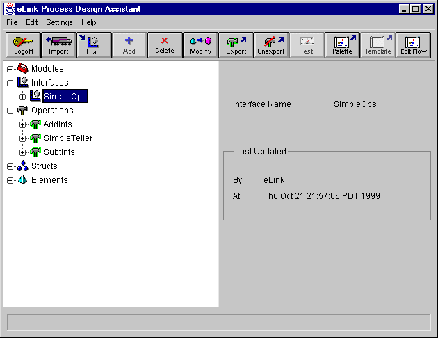
All of the operations contained in the selected interface will be available (and appear on the palette) for use in forming process flows. For example, if you generate a palette from the SimpleOps interface (selected in Figure 4-1), the operations it contains will appear as tasks on the palette.
Figure 4-1 Business Interface Window with Interface Selected
Or
Click on the Palette button.
The Palette Generation Results dialog appears, and a log of the palette generation actions displays in the dialog box.
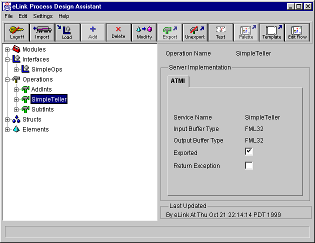
Once you have generated a palette containing the tasks that you want to use in your process flow, you must generate a template from an operation in the Business Interface Window. This template will be the container for your process flow.
To generate a template:
Figure 4-2 Business Interface Window with Operation Selected
Or
Click on the Template button.
The Template Generation Results dialog appears, and a log of the template generation actions displays in the dialog box.
Once you have generated a palette and a template, you must open the Business Process Window so you can form your process flow.
Figure 4-3 Main Window with Edit Flow button
To open the Business Process window:
Or
Click on the Edit Flow button.
The Login Confirmation Dialog Box appears, shown in Figure 4-4.
Figure 4-4 Login Confirmation dialog box
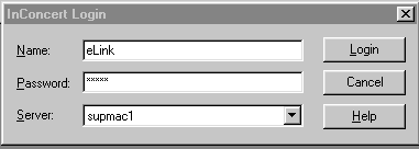
When the Business Process Window opens, you must confirm your login to the Business Process Database. The Login Confirmation Dialog Box will be filled in based on the Business Interface Window login. Click Login to confirm.
After the login is confirmed, the login dialog box closes and the Business Process Window appears.
The toolbar provides menu shortcuts. Every button on the toolbar has a corresponding menu option. The buttons on the left side of the tool bar provide access to Business Process Window applications.
The status bar at the bottom of the Business Process Window displays system messages and abbreviated help text.
Table 4-1 shows the buttons that are on the toolbar as you work in the Business Process Window.
Note: *Tasks and processes must be created as part of the palette and template generation processes to be functional in eLink. The Business Interface Window provides the means for generating these palettes and templates. You can create new tasks and processes with these buttons, but they cannot be used in eLink.
**The Task User Interface Designer is not used in eLink.
This section explains how to use and navigate the Business Process Window. The Business Process Window is used for manipulating processes and the tasks that comprise them. You can modify an existing process definition or modify an active process using the Business Process Window.
To use the Business Process Window, you must open an existing process definition. The process definition opens on a Design Pad.
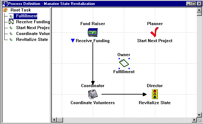
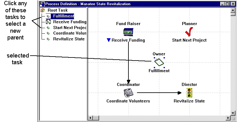
The Design Pad window consists of the hierarchy pane on the left, and the task pane on the right, as shown in Figure 4-5.
Figure 4-5 Design Pad window
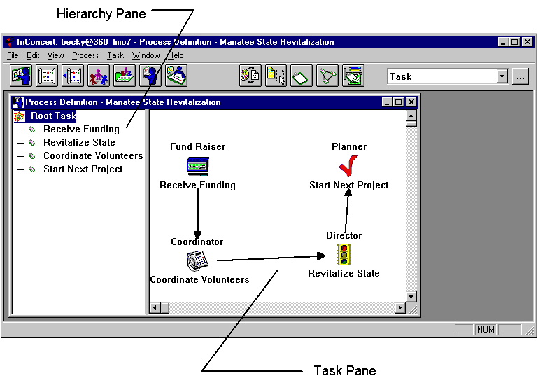
The hierarchy pane displays the structure of the process as a whole. When you select a task in the hierarchy pane, its Child tasks (if any) appear in the task pane.
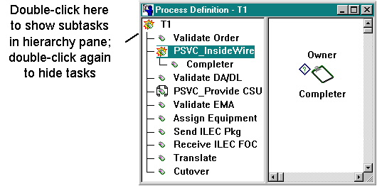
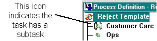
If a task has a subtask, a bracketing icon appears in the hierarchy pane, shown in Figure 4-6.
Figure 4-6 Icon in hierarchy pane indicating subtasks
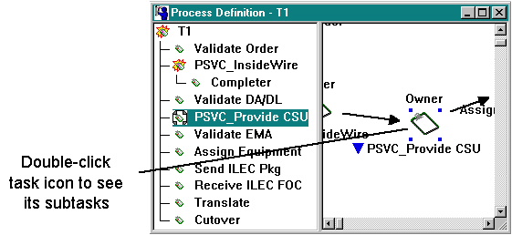
If a task has a subtask, a blue triangle icon appears in the task pane next to the task name, shown in Figure 4-7.
Figure 4-7 Icon in task pane indicating subtasks
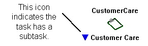
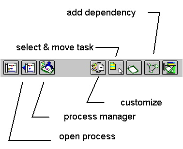
Figure 4-8 shows the buttons that appear on the Business Process window toolbar and what those that are used by eLink do.
Figure 4-8 Buttons on the Process Designer toolbar
The remainder of this chapter explains how to work with the Business Process Window and its sub-windows once the Business Process Window is open.
Occasionally, the Design Pad does not show your most recent change clearly. If this occurs, you can refresh the display.
To refresh the Design Pad:
Press the F5 key, or choose Window > Refresh.
You can print the contents of the hierarchy and task panes.
The first page of the printout shows the contents of the hierarchy pane. The printout includes only visible (expanded) tasks; for example, the root task and its immediate children.
The second page shows the graphical representation of the tasks in the task pane. The print out includes all tasks in the task pane, even if some of the tasks are not currently visible (that is, they are scrolled off screen).
In the printout, task icons are represented by boxes. Task names and attributes are displayed above and below each icon box, just like in the task pane. Dependency arrows are also shown.
The task layout is printed on multiple pages if it does not fit on a single page. The pages are organized from left to right and top to bottom.
To print the Design Pad display:
Choose File > Print.
You can now proceed with other activities immediately because changes in the Business Process Window are saved as you make them. There is no need to explicitly save your work. This ensures that the structural elements of the process are always up-to-date in the database, and that attribute settings are correct.
If you have more design work to do, keep the Business Process Window open. Otherwise, you can close the Business Process Window.
To close the Business Process Window:
Click the  in the top left corner of the process map window.
Most design activity involving the process structure takes place within the task pane of the Design Pad. Use your mouse to perform the following design and layout operations:
You can also copy tasks, and delete tasks and dependencies.
You can switch between layout operations, and "jump" temporarily from one operation to another.
Table 4-2 shows a summary of the design and layout operations.
The section Working with Tasks describes in detail each task operation you can perform in the Design Pad.
To keep the display manageable, the Design Pad shows only selected parts of the process structure. When you select a task in the hierarchy pane, only its immediate subtasks display in the task pane.
You can navigate the process structure from the hierarchy pane, the task pane, or a combination of both. From the hierarchy pane, you can navigate the process structure and show and hide different parts of the process. From the task pane, you can go only to the next lower level of the process.
To navigate from the hierarchy pane:
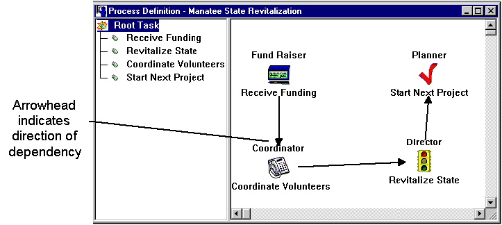
Figure 4-9 A task with a subtask in the task pane
![]() indicating that the task is expanded.
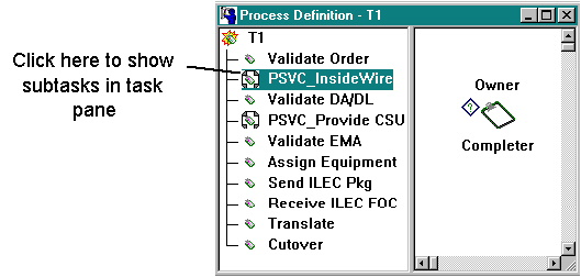
Figure 4-10 shows an example of an expanded hierarchy pane. When you expand
any task (including the Root Task) in the hierarchy pane, its subtasks are
displayed in the task pane.
indicating that the task is expanded.
Figure 4-10 shows an example of an expanded hierarchy pane. When you expand
any task (including the Root Task) in the hierarchy pane, its subtasks are
displayed in the task pane.
To hide a task's children in the hierarchy pane:
Double-click the task name, or select the task and choose View > Collapse. The icon next to the task name changes back to the standard icon.
Note: Collapsing a task in the hierarchy pane often has no effect on the task pane. For example, if you collapse the PSVC_InsideWire task in Figure 4-10, the task pane is unchanged. However, if you collapse a task several levels above that task (for example, the T1 task), the task pane displays the subtasks of that newly selected task.
To navigate from the task pane:
To navigate from the Property Sheet:
Click the Task tab of the Property Sheet. Select a task in the Task Name listbox. The Design Pad display moves and centers on that task.
You can open multiple Design Pad windows and work on different parts of the same process or edit several different processes at once. The advantages of working with multiple Design Pad windows are that you can:
You can open as many additional processes as you want. The Property Sheet tracks task selections only in the active Design Pad.
To work on different parts of the same process:
Choose Window > New Window. The process opens in another Design Pad and any changes you make in one Design Pad are immediately reflected in the other.
You can open the process in as many Design Pads as you like. The Property Sheet is shared among Design Pads, and tracks task selections only in the active Design Pad.
To work on a different process:
Choose File > New > Process Definition or File > Open > Process Designer (see for details), or click the The procedure for copying tasks between Design Pad windows is similar to copying tasks in a single Design Pad.
To copy tasks between Design Pad windows:
Instructions for Working on Different Parts of the Same Process
Instructions for Working on a Different Process
 or
or  buttons on the toolbar.
Copying tasks between Design Pad windows
Instructions for Copying Tasks Between Design Pad Windows
InConcert lets you drag and drop tasks between Design Pad windows as an alternative to cut, copy, and paste. You can drag and drop tasks from one part of a process to another or between processes.
Note: Drag and drop within a process moves the tasks from one part of the process to another. Drag and drop between different processes copies the tasks from one process to another.
There are two ways to drag and drop tasks from one Design Pad to another. The method you choose depends on whether the task pane in the destination Design Pad contains the new parent task. The new parent task does not have to be visible in the task pane, however; when you drag and drop tasks in the Design Pad, the task pane scrolls automatically when you reach the window edge.
To drag and drop a task when the destination task pane contains the new parent task:
Note:
Under some conditions, the Paste Interface option may also appear. This option does not apply to eLink.
If the Design Pad contains the same process, the task and its descendents move to the new location. If the Design Pad contains a different process, the task and its descendents are copied into the process structure.
To drag and drop a task when the destination task pane does not contain the new parent task:
This chapter explains how to use process definitions in your process flow design.
To do this, you must open an existing process definition (template) and make modifications (add tasks from a palette, dependencies between them, parameter assignments, and PerformConditions) to create a process flow.
This section covers this method for forming a process flow. The section of this chapter, Working with Tasks, covers procedures for adding and working with tasks during process design.
You can modify an existing process definition and save it under its original name.
Note: A template generated within the Business Interface Window is the only type of process definition that can be formed into a working eLink process flow.
To prepare for forming a process flow:
button on the toolbar. The
The Process Query dialog box appears, shown in Figure 4-12. You must use a
query to search for the process definition (template or palette).
Figure 4-12 The Process Query dialog box
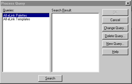
The Queries listbox will contain all of the templates generated from the Process Design Assistant Business Interface Window. If no templates appear in the listbox, you must generate one by returning to the Process Design Assistant Business Interface Window and generate a template according to the instructions in the Generating a Template section of this chapter.
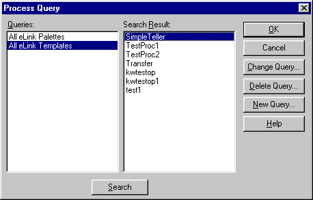
Figure 4-13 Search results in the Process Query dialog box
If no palettes appear in the listbox (Step 2), you must generate one by returning to the Business Interface Window and generate a palette according to the instructions in the Generating a Palette section of this chapter.
In the Property Sheet, the Process tab (shown in Figure 4-14) displays the name, value, and type of each process attribute.
Figure 4-14 Process tab of the Property Sheet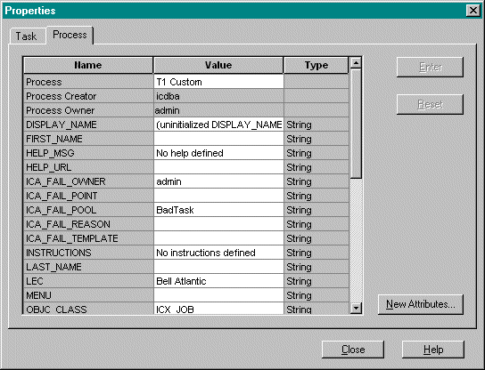
Different attributes take different kinds of values: strings, datetimes, durations, and integers. In most cases, you can select a value from a listbox. In others, you must enter the value yourself, in which case you may only enter the right kind of value. For example, you must enter the task Due Date properly or it will not be accepted.
Table 4-3 describes the internal process attributes. Some internal attributes have meaning only for process instances; the Property Sheet does not show these attributes for process definitions. Moreover, attributes for process instances are read-only in the Property Sheet. For example, the User Working On attribute indicates who is currently working on a task. The Business Process Engine sets this attribute automatically for each task in a process instance; you cannot change it in the Process Designer.
|
Name |
name of process |
string |
|
Process Creator |
name of creator of process |
string |
|
Time Created |
time the process was created |
datetime |
The Business Process Window has validation tools that let you view information about tasks in a process in summary format. When defining processes manually, these tools are necessary to ensure consistency with each definition. However, the eLink Process Design Assistant automates key portions of the procedure, thus removing the need to manually validate definitions.
In this section, you will learn how to copy and modify tasks in a process definition.
You can copy a task in the Task pane and paste it anywhere in the process structure.
Note: The task copying most useful with regard to eLink is to copy a task from a palette to a process definition template.
Each copy includes the task and all its descendants, not just its immediate subtasks. When you paste a task, you insert the entire task structure. You cannot copy multiple tasks at the same time.
There are two ways to copy a task:
You can use the drag-and-drop method only between tasks displayed simultaneously in the task pane; in other words, sibling tasks. However, the new parent task does not have to be visible in the task pane; when you drag-and-drop a task, the task pane scrolls automatically when you reach the window edge.
To copy a task:
Instructions for Copying a Task
Figure 4-15 Copying a task in the Design Pad
To copy a task with drag-and-drop:

In this section, you will learn how to manipulate tasks using the Design Pad interface.
The select-and-move layout mode is the default mode; you can select and move a task without choosing a command from the menu bar or toolbar. If you have not yet selected another layout mode, you need only to perform the correct mouse action to select or move a task. If you have already chosen another layout mode, you can use special mouse operations to select or move a task without leaving the mode.
To select and deselect tasks and dependencies:
 button on the toolbar.

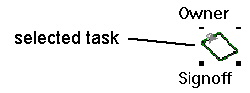
Figure 4-16 Selecting a task in the task pane
To move a task:
To select a task in another layout mode:
To move a task in another layout mode:
Each task icon in the Design Pad has two display areas:
To change the attribute display:
Instructions for Changing the Attribute Display
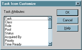
 button on the toolbar. The Task Icon
Customize dialog box appears, shown in Figure 4-17.
button on the toolbar. The Task Icon
Customize dialog box appears, shown in Figure 4-17.
Figure 4-17 The Task Icon Customize dialog box
You can edit task names when using tasks created manually (for instance, parent tasks into which you are placing eLink-generated subtasks). However, when using eLink, the services that run in the applications connected into the eLink environment depend on the names of the tasks used in the Process Design Assistant Business Interface Window. Therefore, generated tasks must not be renamed in the Design Pad as they will not work properly in the eLink environment.
You can automatically place and align tasks in rows or columns in the Design Pad using the Snap to Grid menu option.
When you enable Snap to Grid:
When you close the Process Designer, the state of the Alignment grid is saved to the initialization file and is resumed at the next session.
To align tasks:
Instructions for Aligning Tasks
To hide the alignment grid:
Choose View > Hide Grid.
To show the alignment grid:
Choose View > Show Grid.
Dependencies between tasks determine the order in which tasks can be performed.
The Create Dependencies command lets you add dependencies to tasks. You can also add dependencies while performing another layout operation.
To add a dependency between tasks:
 button on the toolbar.

To add a dependency in another layout mode:
You can remove both tasks and dependencies from the process structure.
To delete a task or dependency:
button on the toolbar.
You can use customized task icons or your own icons, which can be shared with other users.
If you replace an icon, the icon value is cleared and the new icon is displayed.
You are provided a custom icon library. These icons are located in %IC_HOME%\config\icons. You can use these icons or you can add your own customized icon files to this directory.
If you want to share icons with another user, you and the other user must add the same icon libraries to your icons directory. If you do not have a matching icon library, the default icon appears rather than the customized icon.
The icon files are typically the ICO file type. You can store these icon files in a single location if desired.
When you create a task using the Design Pad, the task is displayed using the current default icon. That icon is associated with the task and is displayed whenever you open that process on your PC.
To show or hide the Task Icon Palette:
Choose View > Task Icons > Show Palette. To hide the palette, choose View > Task Icons > Hide Palette.
To change the icon for an existing task using the Task Icon Palette:
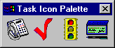
Figure 4-20 The default Task Icon Palette
To add an icon to the Task Icon Palette:
Figure 4-21 The pop-up menu in the Task Icon Palette
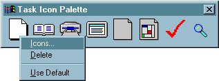
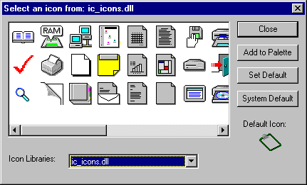
Figure 4-22 The Select an Icon dialog box
To remove an icon from the Task Icon Palette:
In the Task Icon Palette, right-click on the icon you want to remove. A pop-up menu appears, shown in Figure 4-21. Choose the Delete menu item.
To select a default icon using the Task Icon Palette:
In the Task Icon Palette, right-click on the icon you want to become your default icon. A pop-up menu appears, shown in Figure 4-21. Choose the Set Default item from the pop-up menu.
To set the default icon using the Select an Icon dialog box:
To use the system default icon as your default icon:
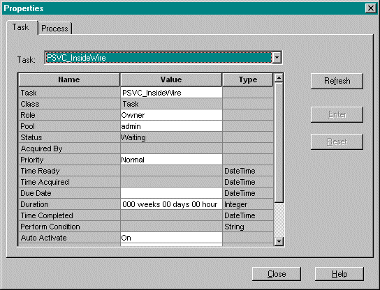
The Property Sheet lets you view and modify task and process attributes.
To open the Property Sheet:
Choose View > Properties. The Property Sheet appears, shown in Figure 4-23. The Task tab displays the name, value, and type of each task attribute.
To view the attribute values for a task:
There are two methods for displaying the attributes of a particular task in the Property Sheet:
Instructions for Viewing the Attribute Values for a Task
To set an attribute value or modify an existing value:
Instructions for Setting an Attribute Value or Modifying an Existing Value
Note:
You can only reset values that have not been committed to the database. Once you click Enter, you cannot reset the value.
To add a process attribute to be used in a PerformCondition:
Note:
You can only perform Step 3 if you have administrative priviledges for your processes.