

|
|
|
|
|
|
Creating the eLink Platform Configuration Files
This section provides instructions for creating the eLink Platform configuration files for the Business Process Option application. This includes specific instructions for using the eLink Platform Configuration utilities to generate these files. Topics include:
BEA eLink Platform provides two utilities to assist you in the configuration process. These are:
Configuration Expert Quick Reference Guide, provides an overview of the main windows and navigation procedures for these utilities.
Note: For more detailed information and instructions on using Configuration Expert, refer to the online document BEA TUXEDO Builder Configuration Expert provided in PDF form with the BEA eLink Platform 1.2 release. This document provides instructions for using Configuration Expert to specifically configure the Business Process Option application.
Note: The examples in this section are taken from a UNIX platform installation. If you are running the Configuration Expert under Windows NT, any local paths, such as the output directory, must be specified following the standard DOS convention of <drive_letter>:\<path>. Any pathnames you specify for the servers must follow the naming convention of the operating system under which the Business Process Servers are to be running.
The eLink Platform Business Process Option Configuration Files
The Configuration Expert uses the information you specify in the configuration screens to generate the following configuration files:
Overview of Configuration Procedures
The steps involved in creating the BEA eLink Platform configuration files for the Business Process Option are as follows:
Step 1: Gather Your Configuration Information
Step 2: Create a New Data Configuration File
Step 3: Create a New Configuration Setup File
Step 4: Configure the Application Properties
Step 5: Add the Machine to the Configuration Tree
Step 6: Configure the Machine Properties
Step 7: Add and Configure the Server Groups
Step 9: Configure the Optional Components
Step 10: Generate the Configuration Files and Scripts
Step 11: Testing the Configuration
Detailed instructions for each of these steps are provided in the following sections.
Step 1: Gather Your Configuration Information
Before you begin the configuration process, you can gather the information you will need to complete the configuration. Configuration Information Checklist, in this manual provides a checklist you can use to complete this step.
Step 2: Create a New Data Configuration File
Before you can create a new configuration, you must create a new Data Configuration file for the server machine(s) you intend to add to the new eLink Platform configuration. This file contains some basic information about the machine(s) and informs the Configuration Expert of the existence of the machine(s).
To create a new Data Configuration file:
On a UNIX platform:
Enter the following commands at the operating system prompt:
cd <$TUXDIR>/eLink/ConfigExpert/bin
./ConfigEditor &
On a Windows NT platform:
Click Start->Programs->BEA eLink->Configuration Expert Setup.
This displays the Configuration Data Editor startup screen.
Note: Refer to the section entitled, Starting the Configuration Data Editor, in Configuration Expert Quick Reference Guide, for an illustration of the Configuration Data Editor startup screen.
Choose File->New to display the Configuration Data Editor main window.
Note: Refer to Starting the Configuration Data Editor, in Configuration Expert Quick Reference Guide, for an illustration of the Configuration Data Editor main window.
Enter the following information in the fields:
After entering all of your machine specification information, click Add. The name of the newly defined machine is added to the Machines list on the left.
Note: Repeat steps 3 and 4 for any other machines that are part of the Business Process Option and eLink Platform installation.
Step 3: Create a New Configuration Setup File
After creating a new machine specification with the Data Editor, the next step is to create a new application configuration setup file. This file is not the eLink Platform configuration file you will generate in the final steps of the configuration process. This file simply provides a framework for collecting the information you enter into the Configuration Expert screen forms. When you have completed the configuration and initiate the file generation process, Configuration Expert reads this file and generates the actual eLink Platform configuration files.
To create a new configuration setup file:
On a UNIX platform:
Enter the following commands at the operating system prompt:
cd <$TUXDIR>/eLink/ConfigExpert/bin
./ConfigExpert &
On a Windows NT platform:
Click Start->Programs->BEA eLink->Configuration Expert.
This displays the Configuration Expert startup screen.
This displays the Create New Configuration window, as illustrated in Figure 6-1.
Figure 6-1 Configuration Expert Create New Configuration Window
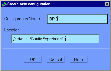
The Configuration Expert creates a file of this name, with the suffix .ce. For example: BPO.ce.
In the Location field, enter the full absolute pathname for the location in which the new configuration file should be written. Do not include the filename - this specifies the location of the file, only. It is recommended that you select the default. To do this, click on the elipsis button (...) to the right of the location field. Select the default. Click OK to submit your selection and go back to the Create New Configuration window.
After you click OK to start a new setup file, the Application Properties window displays, with the General tab selected. The next step in creating a new setup file is to configure the Application Properties. The following section provides instructions for this procedure.
Step 4: Configure the Application Properties
The next step is to configure the Application Properties. The Application Properties define such information as the application name, the IPC Key, level of system access, number of services, and location of the server environment files.
To configure the Application Properties:
There are several ways to go to the Application Properties window:
Figure 6-2 illustrates the Application Properties window with the General tab selected.
Figure 6-2 Configuration Expert Application Properties General Window
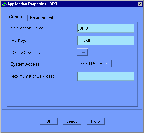
The Application Properties (General) window contains the following fields:
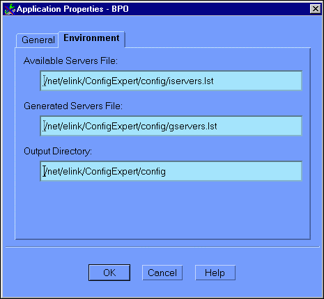
Click on the Environment tab to display the Application Properties (Environment) window, as illustrated in Figure 6-3.
Figure 6-3 Configuration Expert Application Properties Environment Window
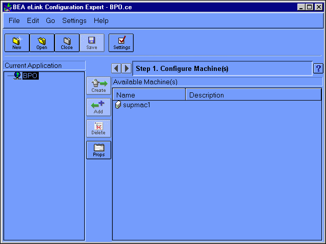
Click OK to submit your Application Properties information and go to the Configuration Expert main window, as illustrated in Figure 6-4.
Figure 6-4 Configuration Expert Main Window
Although you have created a new configuration setup file, it does not yet exist on disk. Choose File->Save to save the new configuration setup file. Each time you choose File->Save at any step in the configuration process, the current configuration information is written to this file.
To save your new configuration specifications, click Save, or choose File->Save or File->Save As. If you choose File->Save As, this displays the Save Application Configuration window, as illustrated in Figure 6-5.
Figure 6-5 Configuration Expert Save Application Configuration Window
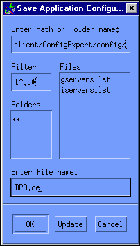
Select the directory to which the configuration should be saved, specify a filename, and click OK.
Step 5: Add the Machine to the Configuration Tree
In Step 2: Create a New Data Configuration File, you defined your server machine and application, and made their existence known to the Configuration Expert. This added the machine to the Available Machines list, but did not add it to the configuration itself. In this step, you add the Business Process Option Server machine to the new configuration by adding it to the configuration tree (left panel in the main window) and thereby make it available for configuration.
To add a machine to the configuration tree:
After completing Step 4: Configure the Application Properties, click OK in the Application Properties window to go to the Configuration Expert main window. The main window displays the machine and application information you specified in the previous steps.
The Configuration Expert main window contains two panels:
Select a machine from the Available Machines list in the left panel.
Click Add to add the selected machine to the Current Application panel on the left. This action also brings up the Machine Properties (General) window for configuring the properties of the machine you just added. You can proceed to the next step to configure the machine you just added, or click OK in the Machine Properties (General) window to configure the machine at another time. You can then repeat the process for Step 5: Add the Machine to the Configuration Tree and continue adding as many machines as you want to configure. Each machine must be configured individually, however. Generally, it is easier to proceed to Step 6: Configure the Machine Properties and configure each machine as you add it, before adding another machine. However, this is not mandatory.
Step 6: Configure the Machine Properties
When you clicked Add in Step 5: Add the Machine to the Configuration Tree, the Machine Properties window automatically displayed, with the General tab already selected. At this point, you can elect to click OK in this window to add the machine to the configuration tree, and then add additional machines before proceding to Step 6: Configure the Machine Properties. Generally, it is more convenient to configure each machine as you add it, before adding additional machines to the configuration tree. To do so, you must repeat Step 5: Add the Machine to the Configuration Tree and Step 6: Configure the Machine Properties for each machine you want to add and configure.
Note: You can also go to the Machine Properties (General) window by selecting the machine you want to configure from the configuration tree (left panel of the main window) and then either clicking the Props button or by selecting Edit->Properties. If you elected to add multiple machines in Step 5: Add the Machine to the Configuration Tree,you will need to use one of these methods to get to the appropriate Machine Properties
To configure the machine properties for the selected machine, click on the tab for each category of properties in the Machine Properties window, and enter your information into the appropriate fields. There are three categories of machine properties:
To configure the machine properties:
When you click Add in Step 5: Add the Machine to the Configuration Tree, the Machine Properties (General) window automatically displays. You can also go to this window by selecting a machine in the configuration tree (left panel), and then either clicking the Props button, or choosing Edit->Properties. Figure 6-6 illustrates the Machine Properties window with the General tab selected.
Figure 6-6 Configuration Expert Machine Properties General Window
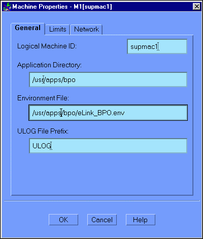
The Machine Properties (General) window contains the following fields:
Click on the Limits tab to display the Machine Properties (Limits) window, as illustrated in Figure 6-7.
Figure 6-7 Configuration Expert Machine Properties Limits Window
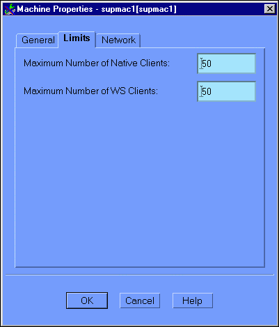
This window contains the following fields:
Click on the Network tab to display the Machine Properties (Network) window, as illustrated in Figure 6-8.
Figure 6-8 Configuration Expert Machine Properties Network Window
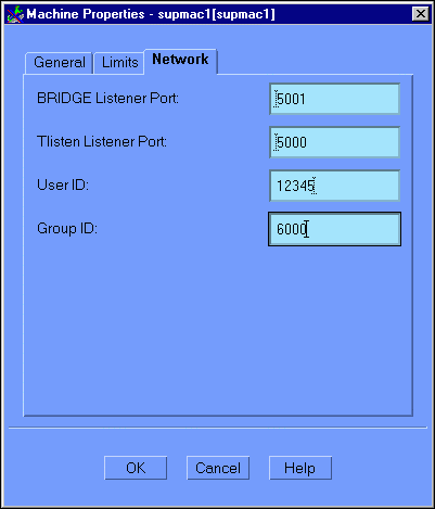
Note: For the standard Business Process Option configuration,which uses only a single machine, it is not necessary to define any Machine Properties Network parameters. Accept the defaults for these parameters.
This window contains the following fields:
After you enter all of the appropriate information, click OK to submit your specifications.
Note: It is recommended that you save your configuration setup file after completing each step, as the information will not be saved automatically. Choose File->Save to save the current file.
Step 7: Add and Configure the Server Groups
The next step is to add the server groups to the configuration and configure each group. You can add and configure one group at a time, or add all of the groups at once, and then configure each group. Each group must be configured individually.
A group is a collection of eLink Platform Servers. Grouping servers facilitates server management by enabling eLink Platform operations (for example, boot or shutdown) to be executed unilaterally across a group.
To add and configure the server groups:
Choose Go->Groups. You can also click the Right Arrow key next to the Step # status message to go to the next configuration step (in this case, Configure Groups). Figure 6-9 illustrates the Configure Groups window.
Figure 6-9 Configuration Expert Configure Groups Window
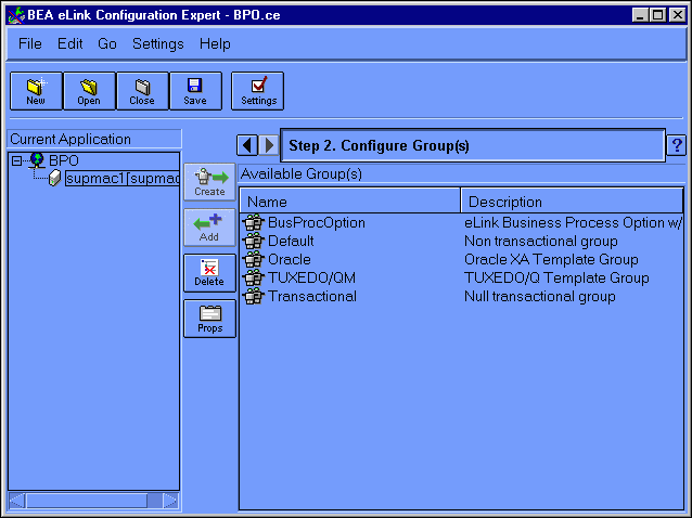
Select the group in the Available Groups list, and then click Add. The group name should now appear in the Current Application configuration tree in the left frame.
Add the following groups to the Current Application configuration tree:
Note: You can customize the list of available server groups by editing the Resource Manager template file. For more information on this procedure, refer to the BEA TUXEDO Builder Configuration Expert online document which is provided on your BEA eLink Platform installation CD-ROM. This document is in PDF form and is readable with Adobe Acrobat Reader.
Select the Default Group in the Current Application configuration tree, and click the Props button (or choose Edit->Properties). This displays the Group Properties (General) window, as illustrated in Figure 6-10.
Figure 6-10 Configuration Expert Group Properties General Window
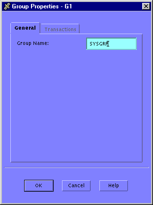
Change the contents of the Group Name field to SYSGRP.
Note: The Transactions tab is greyed out for this group; you need not enter any transaction information for the group SYSGRP.
Follow the same procedure as you did to change the name of the Default group.
Note: It is recommended that you save your configuration setup file after completing each step, as the information will not be saved automatically. Choose File->Save to save the current file.
Step 8: Configure the Servers
The next step is to add and configure the servers. The gservers.lst file defines all servers required by the application. However, if you want to use additional servers - for example, the server mathserv for the MATHAPP sample application - you will need to add those in addition to the servers defined in this procedure. The servers you add are appended to the iservers.lst file.
To configure the servers:
Choose Go->Servers to display the Configure Servers window. You can also click the Right Arrow key next to the Step # status message to go to the next configuration step (in this case, Configure Servers). Figure 6-11 illustrates the Configure Servers window.
Figure 6-11 Configuration Expert Configure Servers Window
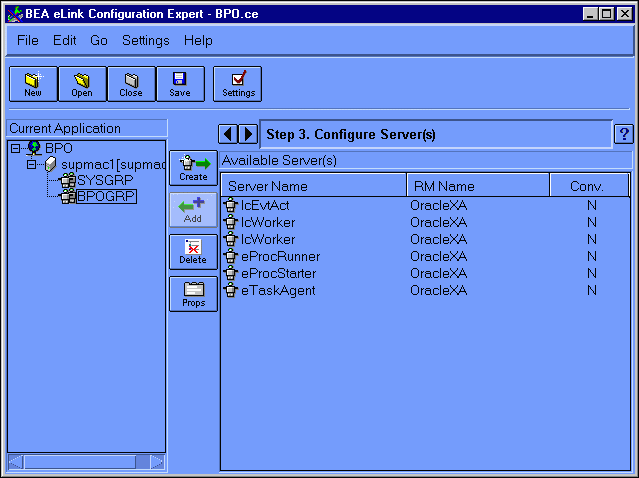
To add the server, do the following:
The IcCliMgr server should now be listed in the Current Applications frame, under the group SYSGRP.
The IcCliMgr server manages the startup and shutdown of certain Business Process Engine services, such as the Repository Daemon.
To configure the general properties for the IcCliMgr server, do the following:
Figure 6-12 Configuration Expert Server Properties General Window
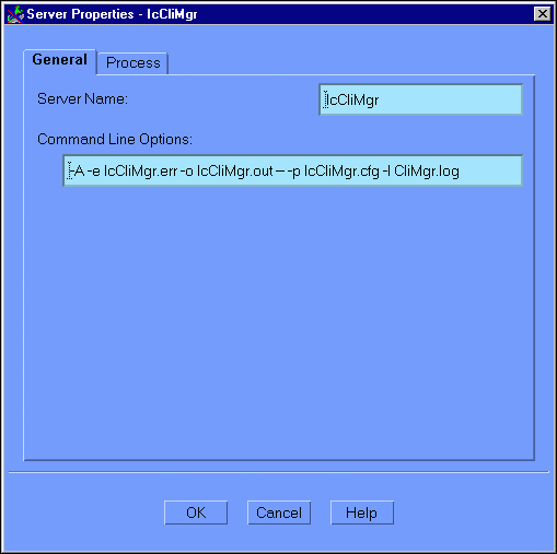
This window contains the following fields:
"/work1/ic/tuxapp/IcCliMgr"
You can optionally change the location of the log files generated by the server. To do so, add the full pathname before both of the .err and .out entries in the Command Line Options field. For example:
Note: A backslash indicates that the command should be written in one continuous line; the backslash is not part of the actual command line.
Before:
-A -e IcCliMgr.err -o IcCliMgr.out --\
-b IcCliMgr.cfg -I IcCliMgr.log
After:
-A -e /bpo/logs/IcCliMgr.err -o /bpo/logs/IcCliMgr.out --\
-b IcCliMgr.cfg -I /bpo/logs/IcCliMgr.log
Warning: This entry consists of two parts: the eLink Platform/TUXEDO-specific options, and the server-specific options. These two portions are separated by two minus sign characters ( -- ). The minus signs must be included in your specification. For information on the platform-specific options, refer to your eLink Platform and TUXEDO UBB file documentation.
Click on the Process tab in the Server Properties window. This displays the Server Properties (Processes) window, as illustrated in Figure 6-13.
Figure 6-13 Configuration Expert Server Properties Process Window
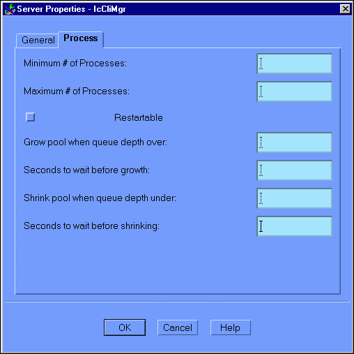
This window contains the following fields:
Note: The following four parameters support the automatic spawning/decaying of servers through the mechanism of the -p eLink Platform/TUXEDO CLOPT parameter. Given the following:
Grow pool when queue depth over = A
Seconds to wait before growth parameter = B
Shrink pool when queue depth under = C
Seconds to wait before shrinking = D
Then the CLOPT line should contain the following:
-p A,B: C,D
Click OK to submit your modifications and return to the Server Configuration window.
Add each of the following servers to the BPOGRP group, in the oder listed.
Note: Add two instances of the IcWorker server.
For each of the BPOGRP servers, do the following:
"/work1/ic/tuxapp/IcCliMgr"
Note: You need not specify an explicit pathname for the eProcRunner, eProcStarter and eTaskAgent servers. However, you must specify the full path to the eLink_BPO.cfg file for each in the Command Line Options field.
To change the log file locations, add the full pathname before each of the .err and .out entries in the Command Line Options field. For example:
Note: A backslash indicates that the command should be written in one continuous line; the backslash is not part of the actual command line.
For the first IcWorker server entry:
-A -e /bpo/logs/IcWorker.err -o /bpo/logs/IcWorker.out --\
-b IcWorker.cfg -I /bpo/logs/GenWorker.log
For the second IcWorker server entry:
-A -e /bpo/logs/IcWorker.err -o /bpo/logs/IcWorker.out --\
-b IcWorker.cfg -I /bpo/logs/IcJobWorker.log
Click on the Process tab in the Server Properties window. This displays the Server Properties (Processes) window, as illustrated in Figure 6-13. The following table provides the Process settings for each server. You can accept the default settings for all fields except those indicated in the table.
Note: For all servers, check the Restartable checkbox.
|
Server Name |
Min. # Processes |
Max. # Processes |
|---|---|---|
|
IcEvtAct |
1 |
1 |
|
IcWorker (IcGen) |
3 |
3 |
|
IcWorker (IcJob) |
1 |
1 |
|
eProcRunner |
1 |
1 |
|
eProcStarter |
1 |
1 |
|
eTaskAgent |
1 |
1 |
Warning: The default installation uses eLink as the Business Process Engine service name suffix. If you change this for any reason during the installation of the Business Process Engine, you must update IcTuxConfig files on both the client machine(s) and server machine(s) to reflect this change. These files are in the following locations:
Client: <PDA_Base_Install_Dir>/Txm/config
Server: <$IC_HOME>/config
In addition, you must change the eLink argument for the -s option in the Command Line Options specification for the following servers:
IcEvt
IcWorker (IcGen)
IcWorker (IcJob)
Note: It is recommended that you save your configuration setup file after completing each step, as the information will not be saved automatically. Choose File->Save to save the current file.
Step 9: Configure the Optional Components
The next step is to add and configure the optional components. The optional components are eLink Platform utility servers or add-ons, such as communication gateways. For the Business Process Option, you must add and configure the following components:
To add and configure these components:
Choose Go->Options to go to the Configure Optional Components window. You can also click the Right Arrow key next to the Step # status message to go to the next configuration step (in this case, Configure Optional Components). Figure 6-14 illustrates the Configure Optional Components window, which comes up with the WS tab selected.
Figure 6-14 Configuration Expert Configuring Optional Components Window
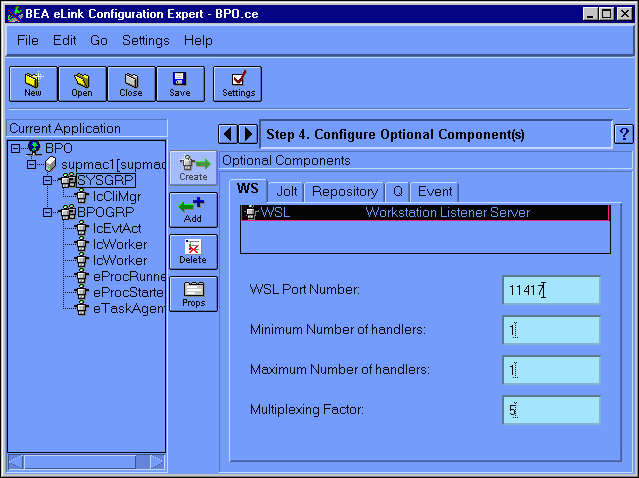
The Configuring Optional Components (WSL) window contains the following fields:
Enter your WSL component specifications and click Add.
To add the eLinkJSL component, do the following:
Figure 6-15 Configuration Expert Configure Optional Components Jolt Window

This displays the Configure Optional Components (Jolt JSL) window, as illustrated in Figure 6-16.
Figure 6-16 Configure Optional Components Jolt JSL Window
This window contains the following fields:
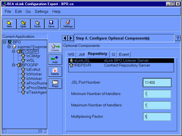
To add the IREPSVR component, do the following:
Figure 6-17 Configuration Expert Configure Optional Components Repository Window
This displays the Configure Optional Components (Repository IREPSVR) window, as illustrated in Figure 6-18.
Figure 6-18 Configure Optional Components Repository IREPSVR Window
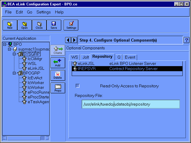
This window contains the following fields:
Choose File->Save to save the current file.
The configuration process is now complete. The next step is to generate the configuration files and scripts, as described in the next section.
Step 10: Generate the Configuration Files and Scripts
After entering all of your configuration information and saving your configuration setup file, you can generate the configuration files and scripts. The Configuration Expert reads the contents of your setup file to generate these files. If you modify the contents of your setup file at any time, you must consequently regenerate the configuration files and scripts for these changes to occur in the configuration.
To generate the configuration files and scripts:
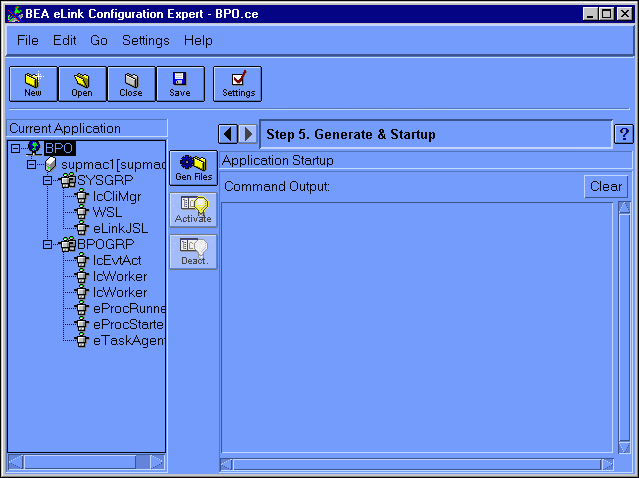
This displays the Generate & Startup window, as illustrated in Figure 6-19.
Figure 6-19 Configuration Expert Generate & Startup Window
This will produce an output listing in the Command Output frame on the left of the Generate & Startup window, as illustrated in Figure 6-20.
Figure 6-20 Configuration Expert Generate Files Output
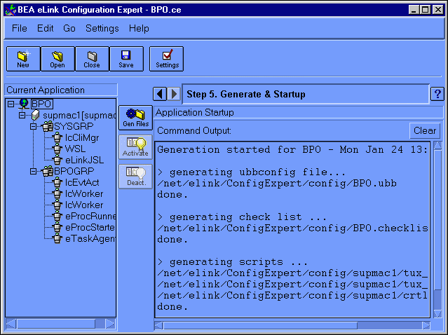
The following files should be generated:
For a description of each of these files, refer to The eLink Platform Business Process Option Configuration Files, in the Overview section of this chapter.
Note: You can move or copy the generated files into the working eLink Platform application directory ($APPDIR, which in this case is the Business Process Option installation directory).
The Business Process Option configuration process is now complete. The next step is to test the new configuration. Instructions for this step are provided in the next section.
Step 11: Testing the Configuration
To test your new configuration, you can use the Configuration Expert Activate feature to perform a preliminary startup of the system. Use one of the following methods:
Figure 6-21 Configuration Expert Step 5: Generate a Startup Window

When the system is started, a series of status and/or error messages are displayed in the Command Output panel in the right half of the main window. You can use the output in this panel to assist in finetuning or debugging your new configuration.

|
|
|
Copyright © 2000 BEA Systems, Inc. All rights reserved.
|