


|

|
|
|
|
Defining the Order Processing Workflow
The following sections describe how to create and define the Order Processing workflow:
Overview of the Order Processing Workflow
The following figure illustrates how the Order Processing workflow diagram should look after you define the entire workflow.
For details on the various workflow components represented by nodes in a workflow diagram, see Chapter 4, "Working with Workflow Components," in the BEA WebLogic Process Integrator Studio Guide.
Figure 2-1 Order Processing Workflow
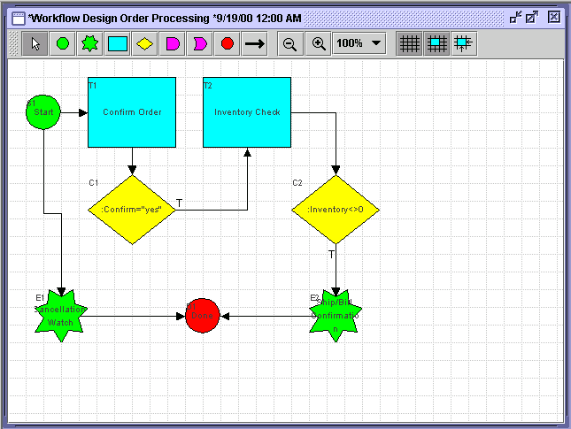
The Order Processing workflow will contain the following nodes:
Table 2-1 Order Processing Workflow Nodes
Creating a New Workflow Template
A workflow template is, in essence, a folder or a container for WebLogic Process Integrator workflow template definitions; each workflow template can hold one or more WebLogic Process Integrator workflow template definitions. Workflow template definitions are essentially different versions of a workflow.
WebLogic Process Integrator workflow template definitions are identified in the folder tree by an Effective and Expiry date; these are discussed in "Understanding Effective and Expiry Dates" of Chapter 3, "Defining and Maintaining Workflows" in the BEA WebLogic Process Integrator Studio Guide.
To create the Order Processing workflow template:
Figure 2-2 Logon to WebLogic Process Integrator Dialog Box

Figure 2-3 Create Template
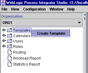
The Order Processing workflow template will be added under the Templates folder.
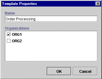
Figure 2-4 Template Properties Dialog Box
Creating a New Workflow Template Definition
To create a new workflow template definition for the new workflow template:
Figure 2-5 Create Template Definition
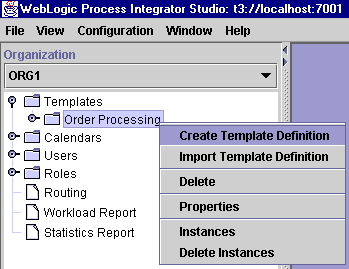
Figure 2-6 Template Definition Dialog Box
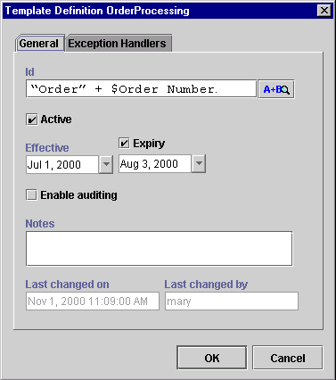
The Effective and Expiry dates allow you to make the workflow template definitions valid for a specific range of time. Each workflow template can contain one or more workflow template definitions, distinguished by the Effective and Expiry dates. At run time, the processing engine chooses the most effective workflow template definition for the specified workflow template, the most effective being the most current template definition that is marked Active.
Drawing the Flow
Once you complete the Template Definition dialog box and click OK, the drawing area is displayed with a simple predefined workflow containing a start node, a task node, and a done node. From the toolbar, you choose the icons that represent nodes and other elements that you use to draw the flow. (Nodes in the drawing area are also referred to as shapes.)
Figure 2-7 Workflow Drawing Area
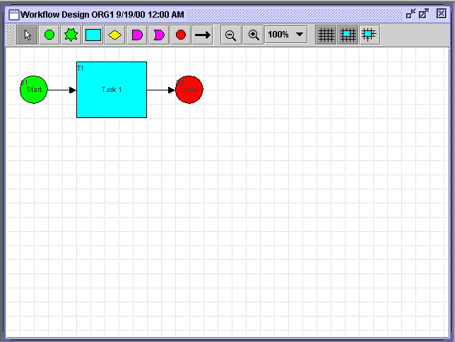
The Processing Order workflow requires the following nodes:
Placing Node Icons (Shapes) in the Drawing Area
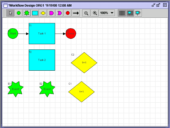
Place a shape in the drawing area by clicking its icon in the toolbar and then clicking the drawing area. This drops the shape (representing a workflow node) in the drawing area. Follow this procedure to place one task, two events, and two decisions in the drawing area. (The start and done nodes and one task node are already represented.)
You can move shapes within the drawing area by dragging and dropping them anywhere in the drawing area.
Figure 2-8 Shapes Placed in Drawing Area
Connecting the Nodes
Next, you connect the shapes in the drawing area to form the flow of the workflow. You connect shapes in one of two ways:
To connect the nodes:
Note: A Decision node contains a condition, which can be either True or False. If the condition within the Decision node is verified as True, the workflow continues to Task 2.
Note: A decision node contains a condition, which can be either True or False. If the condition within the decision node is verified as True, the workflow continues to Task 2.
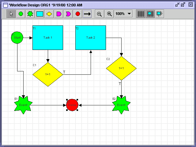
You should have the following flow.
Figure 2-9 Completed Drawing
Renaming Nodes
Next, you will rename nodes in the drawing area.
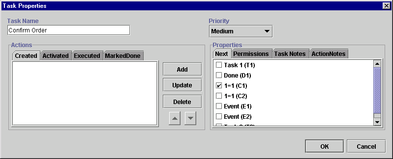
Task 1 (T1) Node
This dialog contains the names of the nodes in the drawing area.
Figure 2-10 Task Properties Dialog Box
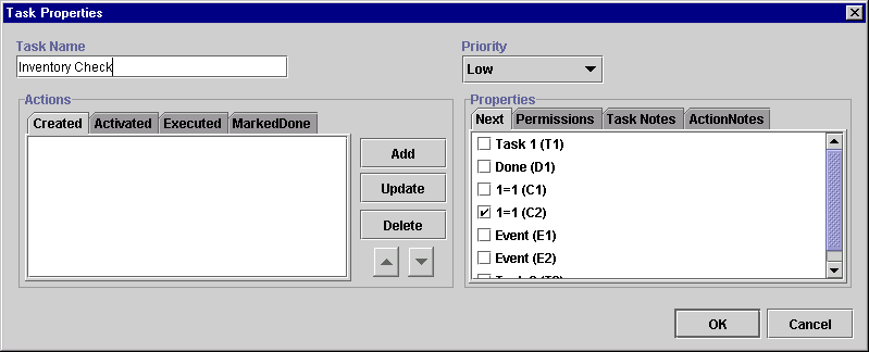
Task 2 (T2) Node
Figure 2-11 Task Properties Dialog Box
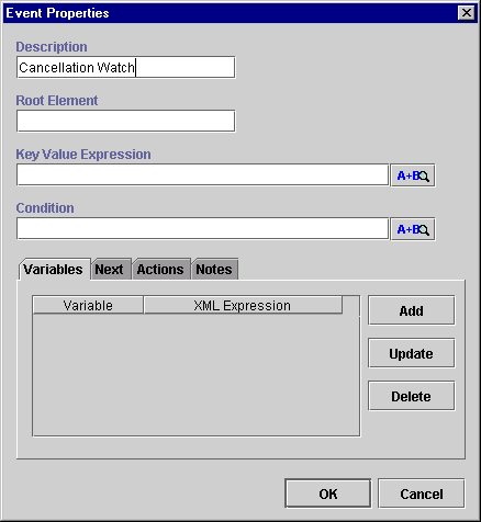
Event 1 (E1) Node
Figure 2-12 Event Properties Dialog Box
Event 2 (E2) Node
Figure 2-13 Event Properties Dialog Box
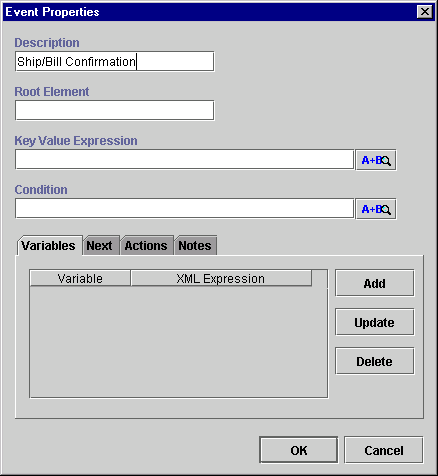
Figure 2-14 Final Flow
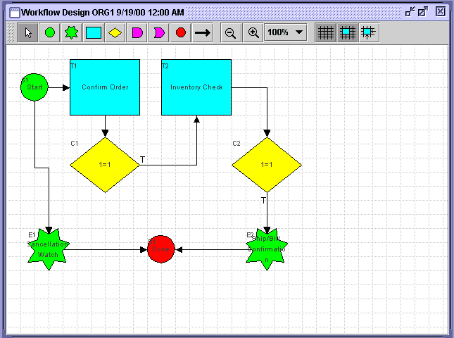
After you connect all the nodes, you will define variables for the workflow; add the appropriate properties to each node; and define the actions for each node. These actions are executed at run time upon the instantiation of the workflow. Instantiation means that the workflow is started or placed into run time.
Defining Variables
Each workflow has a set of variables associated with it. A variable is typically used to store application-specific information required by the workflow at run time. This information is often used to control the logic within a workflow.
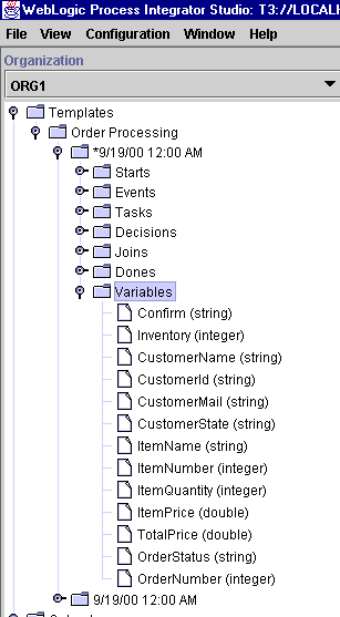
The Order Processing workflow requires the following variables.
You will also need to define some of these variables for the ShipBill workflow that will be called by this workflow.
To define the variables for the Order Processing workflow:
Figure 2-15 Create Variable
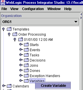
The Variable Properties dialog box is displayed.
Figure 2-16 Variable Properties Dialog Box
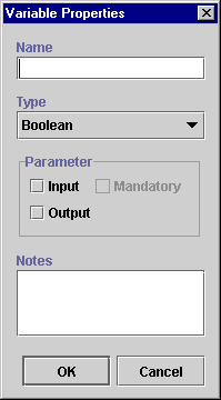
You will define all of the variables in the preceding table using the Variable Properties dialog box. For example, you will begin by defining the variable Confirm, which is a string type variable. It is a user confirmation response, and its possible values are Y (yes) or N (no).
Note: For now, you will only enter the variable name and type. You will define the possible values later in this tutorial.
To define this variable, proceed as follows:
Figure 2-17 New Variable
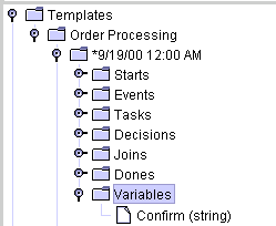
Figure 2-18 New Variables List
Defining Business Operations
In WebLogic Process Integrator, a business operation represents a method call on an Entity/Session EJB or Java class instance. This method call is added to a workflow in WebLogic Process Integrator through use of the Perform Business Operation action. The invocation results of this action can be assigned to the workflow variables.
Entity/Session EJBs represent a component architecture for developing and deploying object-oriented, distributed, enterprise-level applications. The Business Operations feature, in effect, allows for the creation of customized actions, which create the connection between WebLogic Process Integrator and end-user applications and components.
The WebLogic Processing Integrator Business Operations facility enables business analysts to design workflows that invoke the methods of Java objects and Enterprise Java Beans (EJBs) that are registered in WebLogic Sever (WLS). Using this Business Operations facility, you provide a descriptive name for the remote methods and parameters of the Entity/Session EJBs or Java classes that you wish to deploy, thus providing non-technical users with an understanding of the business meaning behind these remote methods and parameters.
Using the Define Business Operation dialog box, you will define two Session EJB business operations. These business operations represent remote methods of invoking the wlpi.tour.POBean JavaBean. This JavaBean is used in the workflow to check the inventory for the item ordered and return the results to the workflow.
The business operations are:
Defining the Check Inventory Business Operation
To define the first business operation, Check Inventory, which is called from the Order Processing workflow and returns the number of items available in stock:
Figure 2-19 Business Operations Dialog Box
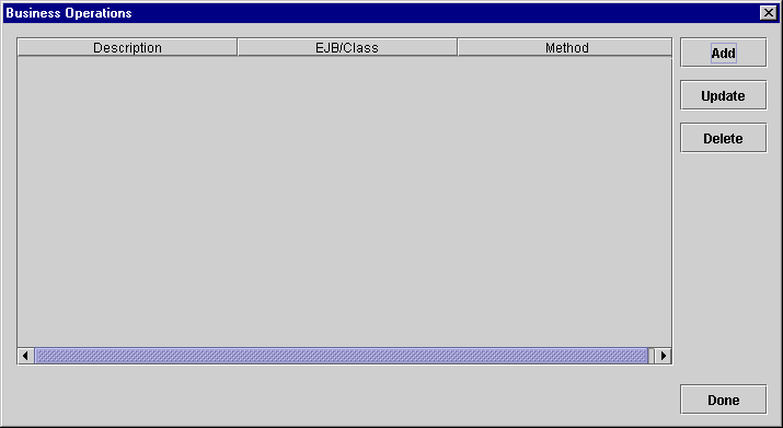
Figure 2-20 Define Business Operation Dialog Box
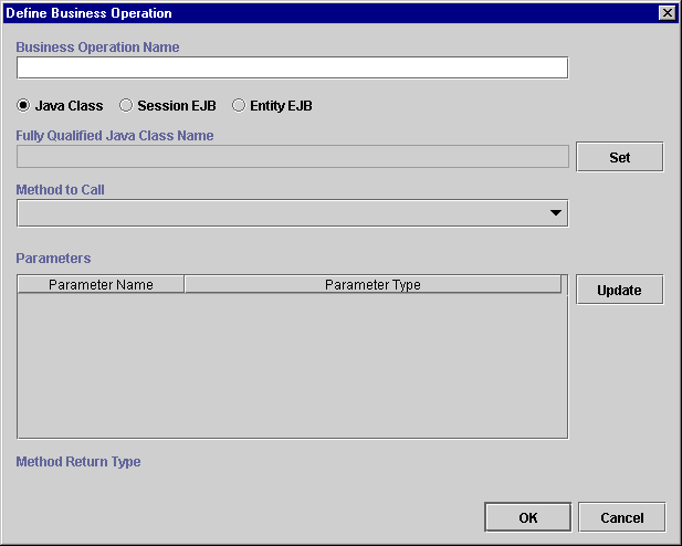
Next, you will select the type of business operation that you are defining. The choices are:
Entity beans most often represent the internal state of WebLogic Process Integrator. They are often deployed by other Entity beans on WebLogic Server. In general, an Entity bean represents an object with persistent data that behaves transactionally. Unlike Java classes, WebLogic Process Integrator does not persist an Entity bean's data in a workflow instance. Instead, WebLogic Process Integrator maintains a reference to the Entity bean as part of the workflow instance data. This fact implies that the underlying entity bean can be modified or even deleted outside of the control (or knowledge) of the workflow instance.
Figure 2-21 Create Session EJB Business Operation
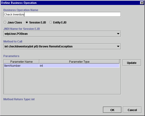
JNDI is a service provided by WebLogic Server; this service stores objects much like a database. Here, you are selecting the JNDI name for the Session EJB; a Session EJB is an object stored in this service.
Figure 2-22 Parameter Dialog Box

Note: The parameter type is displayed for each parameter; these parameters are already defined.
Defining the Calculate Total Price Business Operation
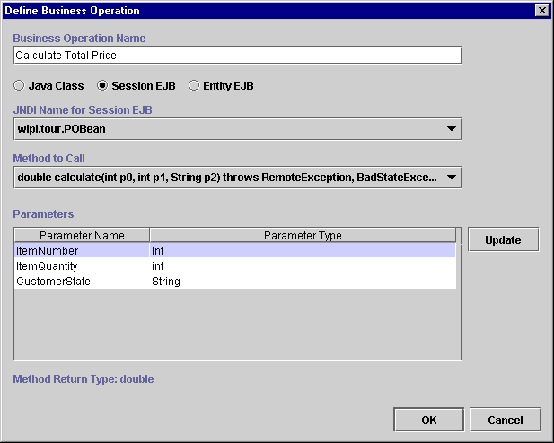
To create the next business operation, Calculate Total Price, which calculates the total price of the order and is called within the workflow ShipBill:
Figure 2-23 Parameter Dialog Box

Note: The parameter type is displayed for each parameter.
Figure 2-24 Calculate Business Operation
Defining the Create PO Bean Business Operation
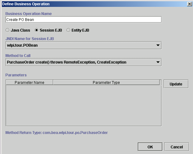
To define the final business operation, Create PO Bean, which creates the POBean object for the Order Processing workflow:
Note: This method contains no parameters.
Figure 2-25 Create PO Bean Business Operation
After Business Operation Creation
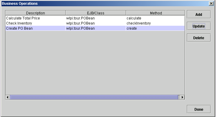
The Business Operations dialog box now contains the three business operations you have just defined.
Figure 2-26 Business Operations Dialog Box
Once you have defined the business operations, you can call them from the workflow using the Perform Business Operation action. This action calls the business operations from the workflow. Instructions for using the Perform Business Operations action are provided in Define Inventory Check Task and in Defining the ShipBill Workflow: An Exception Handling Example.
Defining Tasks
A workflow consists of a series of tasks, each of which represents a discrete activity to be performed automatically by the WebLogic Process Integrator server or by a workflow end user by using the worklist application. In this section, you define the tasks in the Order Processing workflow.
Defining the Confirm Order Task
To define the Confirm Order task:
Figure 2-27 Task Properties

Confirm Order is the first task in this workflow. At run time, this task is performed by an end user. Therefore, it is assigned to an actual user and is displayed on that user's worklist upon instantiation of the workflow.
The tabs on the left side of the dialog box display four separate lists of actions for the tasks that are performed at the four task events. A task responds to an event at run time by executing the associated actions. The four task events are:
You are now ready to add the new Assign Task to User action.
Figure 2-28 Add Action Dialog Box
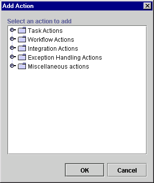
Actions are the basic building blocks of the workflow. They can be defined within tasks, events, decisions, starts, and as a subaction of an action itself.
The action categories are Task, Workflow, Integration, Exception Handling, and Miscellaneous. The task category contains all actions relevant to tasks, including actions that allow the assignment of tasks to users and roles.
Figure 2-29 Add Action Dialog Box
Figure 2-30 Assign Task to User Dialog Box
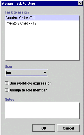
The Assign Task to User action is displayed in the Activated tab.
Figure 2-31 Task Properties: Assign Task to User Action
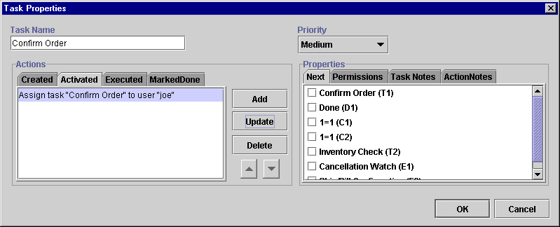
The Confirm Order task, upon execution, prompts the user to confirm the order. The Decision node that succeeds the task directs the flow according to the user's response.
The action that allows the user to interact with the worklist and enter a response to a question or value for a variable is Send XML to Client in the Integration Actions category.
Figure 2-32 Integration Actions
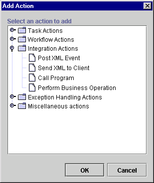
Proceed to the next section, Defining the XML Document Structure, to continue defining the Confirm Order task.
Figure 2-33 Send XML to Client Dialog Box
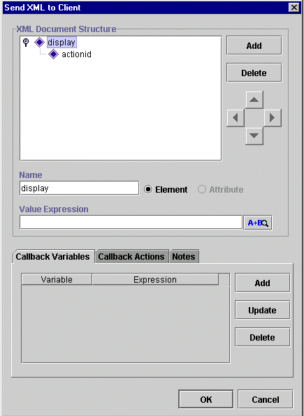
Understanding the XML Document Structure
In the Send XML to Client dialog box, you define an XML document, which will be sent out to the client application. The client application should be programmed to identify this XML document, respond to it appropriately, and send an XML document to the WebLogic Process Integrator server with information that can be used to populate workflow variables. The WebLogic Process Integrator Worklist responds to certain default setups of this action.
Default structures for the XML document can be used to:
To prompt the user for a simple Yes/No confirmation, the XML document must have the following structure, where:
Defining the XML Document Structure
Refer to the following figure and procedure to define the XML document structure. The following figure shows how the Send XML to Client dialog box should look after you complete the procedure.
Figure 2-34 Final XML Document Structure
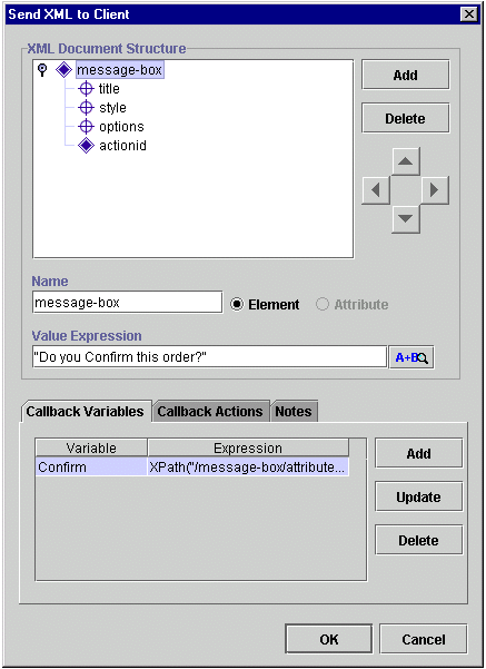
To define the XML document structure:
XPath("/message-box/attribute::option")
Note: If you know XML, you can type the expression directly into this field. Otherwise, click the A+B button to access the Expression Builder. For instructions on using the Expression Builder, see Chapter 6, "Using Expressions and Conditions," of the BEA WebLogic Process Integrator Studio Guide and Using the Expression Builder in this document.
BEA WebLogic Process Integrator uses the XPath XML model. For information on XPath, refer to the following Web site: http://www.w3.org/TR/xpath.html. Also, refer to Chapter 6, "Using Expressions and Conditions," in the BEA WebLogic Process Integrator Studio Guide.
Figure 2-35 Workflow Variable Assignment
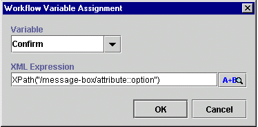
In the example here, the user's response will be stored in the workflow variable Confirm as defined in the Callback Variables tab in the lower part of the Send XML to Client dialog box.
Using the Expression Builder
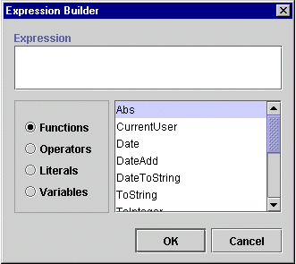
You use the Expression Builder to define the value of the variable coming back in an XML document from the worklist client application. The function XPath is used to parse the XML document and extract the relevant value from it.
The Expression Builder, available in dialog boxes where you see A+B, enables you to build expressions, by using predefined functions, literals and operators, which will be evaluated and executed at run time. Workflow variables are usually used in expressions. Clicking A+B in any dialog box displays the Expression Builder dialog box.
Figure 2-36 Expression Builder
See Chapter 6, "Using Expressions and Conditions," of the BEA WebLogic Process Integrator Studio Guide for detailed explanations of each function available in the Expression Builder.
Define Inventory Check Task
Upon activation, the Inventory Check task calls the JavaBean POBean, which checks the inventory for the item ordered and returns the results to this workflow.
To define the Inventory Check task, you create two Perform Business Operation actions, which perform the business operations you defined in Defining Business Operations, and one Mark Task as Done action, which marks the task as done once the two business operations are complete.
Defining the Create PO Bean Perform Business Operation Action
To define the Create PO Bean Perform Business Operation action, which creates the POBean object:
Figure 2-37 Add Action: Perform Business Operation
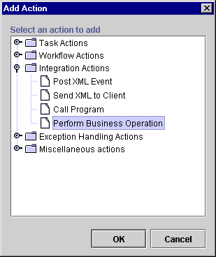
Figure 2-38 Perform Business Operation Dialog Box
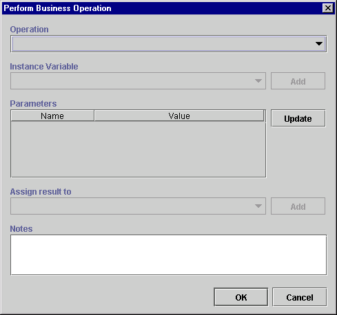
Note: No parameters are associated with the Create PO Bean business operation, since it represents a home method session EJB.
The Assign result to (int) drop-down list already contains the value associated with this business operation, PoBeanHandle.
Defining the Check Inventory Perform Business Operation Action
To define the Check Inventory Perform Business Operation action, which returns the total number of items in stock:
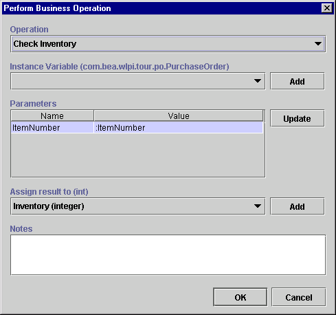
Instance Variable, Parameter Name, and Assign result to are already populated with values correlating to the Check Inventory business operation.
Figure 2-39 Expression Builder Dialog Box
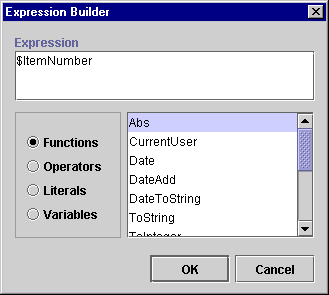
The Value field of the Perform Business Operation dialog box is now populated with the $ItemNumber parameter value.
You have now placed the value of the variable ItemNumber as the input parameter to the JavaBean POBean and the variable Inventory (integer) will get the result back from the execution of this JavaBean.
Figure 2-40 Perform Business Operation Dialog Box: Check Inventory
Defining the Mark Task as Done Action
You will now add the Mark Task as Done action to the Activated tab of the Task Properties dialog box. This action marks the task as done once all other actions within this task are performed and activates the C2 Decision node.
Figure 2-41 Mark Task as Done Dialog Box
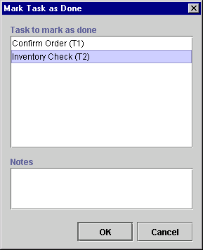
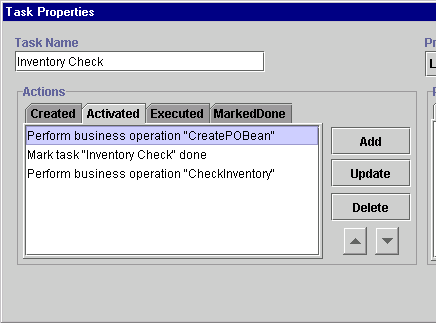
The Activated tab of the Task Properties dialog box now contains three tasks that will be executed upon activation of the workflow. (See Figure 2-42.)
Figure 2-42 Activated Tab
Defining Decisions
A decision allows you to control the flow by evaluating a condition as true or false. Actions can be defined within the decision for each true or false case. The Order Processing workflow contains two decisions: one decision evaluates whether the user has confirmed the order, and the other confirms whether the inventory is available. If the inventory is available, the Order Processing workflow starts the ShipBill workflow, discussed in Defining the ShipBill Workflow: An Exception Handling Example.
Decision: Has Order Been Confirmed?
The first decision checks whether the user has confirmed the order. If the order has been confirmed, the flow continues to the next task Inventory Check. If the order has not been confirmed, an XML message is sent to cancel the workflow; the Cancellation Watch event in the workflow is triggered by this XML message, and the succeeding done node will cause the workflow to cancel.
Defining the C1 Decision Node
To define the C1 decision node:
Figure 2-43 Decision Properties Dialog Box
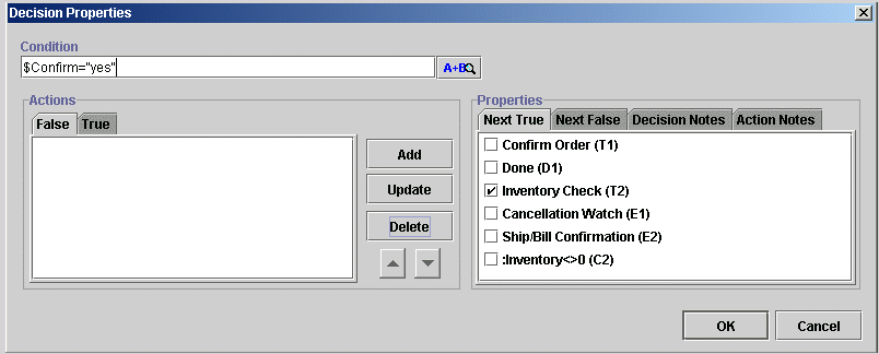
This condition evaluates whether the user has responded Yes or No to the confirmation of the order. If the condition is true (the user has double-clicked Confirm Order in the worklist and responded Yes to the Confirm Order message), the flow moves to the next node. If the condition is false, an XML message is sent to the workflow server, which cancels the order.
Figure 2-44 Decision Properties Dialog Box
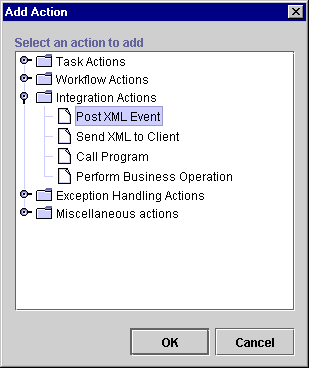
Figure 2-45 Post XML Event Dialog Box

Defining the XML Document Structure
In the Post XML Event dialog box, you define an XML document. In this example, the XML document has the root element order and two subelements:
To define the XML document structure:
Figure 2-46 Post XML Event Dialog Box
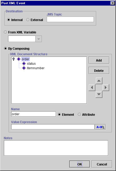
Figure 2-47 Decision Properties Dialog Box
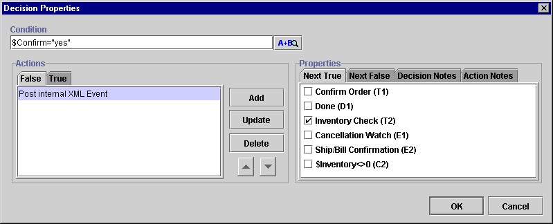
As you will see in the Defining Events section, the event Cancellation Watch will be triggered by this particular XML document.
Decision: Is Item Available?
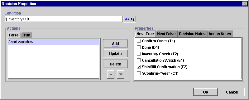
This decision evaluates the value of a variable that is set as the result of a call to the JavaBean POBean. The value is the quantity in stock of the ordered item. If this number is zero, the order is cancelled. If the number is greater than zero, the ShipBill workflow is started by the Start Workflow action and the flow moves on to the next node, which is the Ship/Bill Confirmation event. (In this example, the available number of items is greater than the numbers of items ordered.)
To define the C2 Decision node:
This expression can be typed directly into the Condition description field or can be constructed using the Expression Builder, accessed by clicking the A+B button. This condition evaluates whether the user has responded Yes or No to the confirmation of the order.
Figure 2-48 Abort Workflow Dialog Box
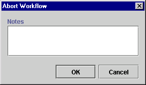
Figure 2-49 Decision Properties Dialog Box: Abort Workflow Action
The Start Workflow action enables you to start a sub-workflow (in this case, ShipBill) from the current workflow, Order Processing.
Figure 2-50 Start Workflow Dialog Box
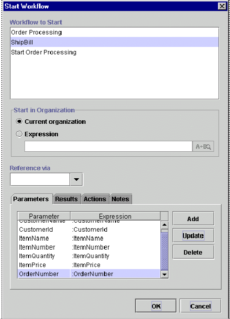
In this example, the organization will remain ORG1, and the value of some variables are transferred from the Order Processing workflow to the ShipBill workflow.
As the example progresses, the variables in the "child" workflow (ShipBill), which will receive values from the "parent" workflow (Order Processing), will be defined as input variables within the variable definition dialog box. All input variables of the child workflow will automatically be displayed. Ordinarily, you can then use the Expression Builder to assign values to them. (In the example, we are simply transferring the values of the variables in the current workflow.)
Defining Events
An event is a notification node. An event is triggered by the arrival of an XML document that is produced internally within the WebLogic Process Integrator processing engine or from an external source through a Java Message Service (JMS) topic. When the flow reaches an event node, it waits until that event is triggered. An event can be cancelled by using the Cancel XML Event action.
The example contains two events: one event waits for the cancellation message, and the other event is triggered upon receipt of the shipping and billing confirmation in order to complete the order.
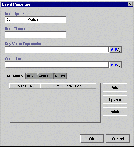
Event: Cancellation Watch
To define the Cancellation Watch event:
Figure 2-51 Event Properties Dialog Box
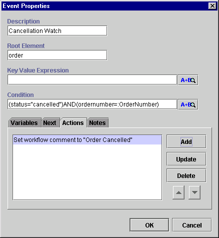
(status="cancelled")AND(ordernumber=:OrderNumber)
Figure 2-52 Event Properties Dialog Box
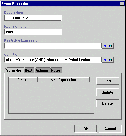
No further actions will be performed within this event, and the flow will move to the next node, which is the done node. However, in order to distinguish between a cancelled order and a completed one (having reached the done node of the workflow), you will add a workflow comment that will be displayed on the monitoring window upon execution of this workflow and when the cancellation occurs.
Figure 2-53 Add Action Dialog Box
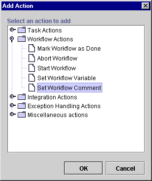
Figure 2-54 Set Workflow Comment Dialog Box
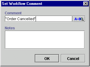
Figure 2-55 Event Properties Dialog Box
Event: ShipBill Confirmation
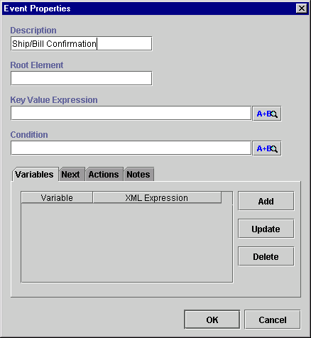
Next, you set up the ShipBill Confirmation event, which waits for the ShipBill workflow to send back an XML document confirming the shipping and billing for the ordered item. (The ShipBill workflow is predefined for this example and is discussed in Defining the ShipBill Workflow: An Exception Handling Example.)
The root element of the XML message that will trigger this event is order, the same element that triggers the Cancellation Watch event. The condition, however, is different. For this event to be triggered, the status has to be "complete".
The total price of the item calculated by the JavaBean POBean in the ShipBill workflow is also returned to this workflow through the XML document.
To define the ShipBill Confirmation event:
Figure 2-56 Event Properties Dialog Box
status="complete"
Next, you will set up an XML document, which returns the total price of the item calculated by the JavaBean POBean in the ShipBill workflow to the Order Processing workflow.
Figure 2-57 Workflow Variable Assignment Dialog Box
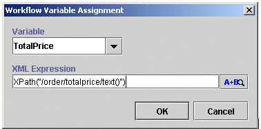
XPath("/order/totalprice/text()")
Your final Event Properties dialog box should look like the following figure:
Setting Up the Trigger
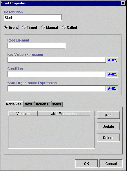
The Order Processing workflow is an event-triggered workflow. An XML document will be constructed and sent from the Start Order Processing workflow to trigger the Order Processing workflow. You specify the trigger conditions for the workflow in the Start node. There are four ways to start a workflow:
This example uses the Event method. The root element of the XML document will be order, and the condition is status="new". The organization for which this workflow should be instantiated also must be specified. Once this workflow is triggered, some of the variables will be populated by values contained in the XML document.
To set up the XML document that will trigger the Order Processing workflow:
Figure 2-59 Start Properties Dialog Box: Event
status="new"
"ORG1"
Next, you will construct an XML document by defining the variable CustomerName to extract the value of the element name from the root customer.
Figure 2-60 Workflow Variable Assignment Dialog Box
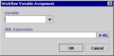
XPath("/order/customer/name/text()")
Figure 2-61 Start Properties Dialog Box

Setting Up the Workflow Template Definition Processing Properties
In order to process the Order Processing workflow, you must set up certain workflow template definition processing properties. The workflow must be marked as Active in the Properties dialog before it can be instantiated.
To set up the workflow template definition processing properties:
Figure 2-62 Template Definition Order Processing Dialog Box
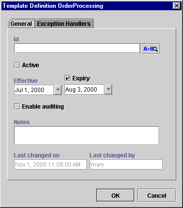
The ID for the Order Processing workflow will be displayed on the worklist and on the monitoring screens. This ID is unique for each instance of this workflow; it is an expression built using workflow variables.
You already defined the Effective and Expiry dates when you created the workflow template definition for Order Processing in Creating a New Workflow Template Definition.
Figure 2-63 Template Definition Order Processing Dialog Box

Note: For instructions on using the Exception Handlers tab to set up an exception handler, see Defining the ShipBill Workflow: An Exception Handling Example.

|

|

|
|
|
|
Copyright © 2001 BEA Systems, Inc. All rights reserved.
|