
| Download Docs | Site Map | Glossary | |
|
|
|||
| bea.com | products | dev2dev | support | askBEA |
 |
 |
|
|||||||
| e-docs > WebLogic Platform > WebLogic Integration > BPM Topics > Using the Studio > Using the Studio Interface |
|
Using the Studio
|
Using the Studio Interface
This section explains how to start the Studio, and provides an overview of the Studio graphical user interface:
Starting and Logging On to the Studio
To start the Studio, do one of the following:
For example, if WebLogic Integration is installed in the /home/bea/weblogic700/integration directory, enter the following:
cd /home/bea/weblogic700/integration/bin
. ./studio
The Logon to WebLogic Integration dialog box is displayed.
Figure 2-1 Logon to WebLogic Integration Dialog Box
To log on to WebLogic Integration:
Figure 2-2 WebLogic Integration Studio Main Window
Overview of the Studio Interface
This section describes the parts of the Studio user interface, and the functions they provide.
Menu Options
The following sections provide information about using the menu bar in the Studio.
File Menu
Choose File
View Menu Choose View
Configuration Menu Choose Configuration
Tools Menu Choose Tools
Help Menu Choose Help
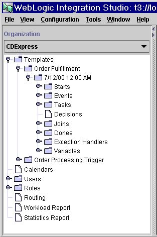
Folder Tree Display The WebLogic Integration Studio interface contains a folder tree display, which organizes workflow components in a standard tree structure. Figure 2-3 WebLogic Integration Folder Tree Display
To select a different organization, use the Organization drop-down list at the top of the window. To view details about any of the following items shown in the folder tree display, double-click the item to expand it:
For example, double-click the Templates folder to display a list of workflow templates. Double-click a workflow template to display a list of all workflow template definitions. Expanding a particular workflow template definition displays folders containing the Tasks, Decisions, Events, Joins, Starts, Dones, and Variables for that workflow template definition.
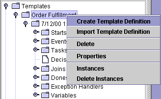
You can right-click most items in the folder tree to display a menu containing options relevant to the highlighted item. For example, right-click on an existing workflow template to display a menu with the options shown in the following figure.
Figure 2-4 Workflow Template Menu Options
Workflow Design Area and Toolbar Once you have created or opened an existing workflow template definition (for procedures, see Working with Template Definitions), the workflow design area, shown in the following figure, is where you create your workflow designs. The workflow toolbar contains the shapes representing workflow nodes and the connections you use to define a workflow. Figure 2-5 Workflow Design Window
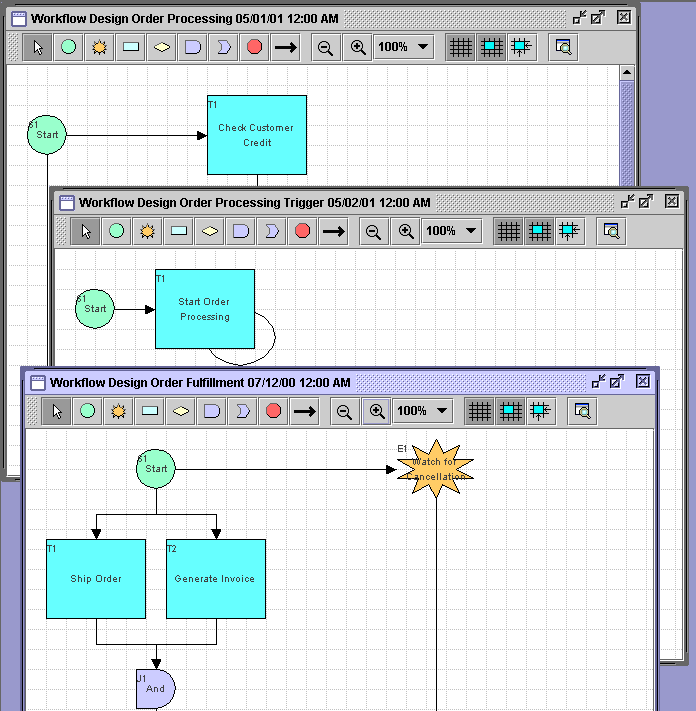
You can have multiple workflow designs open simultaneously. You can view more than one workflow, and toggle back and forth between them. Figure 2-6 Multiple Workflow Diagrams
Using the Toolbar The toolbar also contains the following toggle controls:
By default, the workflow toolbar appears at the top of the drawing area. Depending on the size of the Studio window or drawing area, you might not be able to see the entire toolbar. To see the entire toolbar, relocate the toolbar to another part of the Studio drawing area, or to another location on your desktop.
To relocate the toolbar, click the background area of the toolbar (for example, the space between the Draw Connection and Zoom Out button), and drag the toolbar to the desired location.
If you drag the toolbar to another location on your desktop outside of the Studio drawing area, the toolbar becomes a separate window on your desktop, which you can minimize, maximize, and close.
Using Interface View
Once you have created a template definition, begun to define nodes and add actions to them, it is often useful to see the objects to which a workflow interfaces, according to the nodes that reference those objects. You can use the Interface View to display the components in the workflow diagram, plus icons representing the following objects to which the workflow can interface:
Interface View is disabled by default. To use Interface View, you must turn it on for each template definition, and for each new session in which you access the same template definition.
By contrast, Interface View preferences, which determine the objects that are visible, are set system-wide; that is, they apply to all template definitions. They are saved from session to session in the Studio; they are not saved as part of the template definition.
To specify the objects you want to view:
Figure 2-7 Interface View Preferences Dialog Box
To toggle between a normal and interface view for the current template definition, click the following button in the toolbar: 
Viewing Inbound XML Document Data
In an interface view, the following icon represents an inbound XML document in the workflow diagram.
Note: The arrow points toward a template node to indicate inbound direction. An inbound XML document icon is displayed for Start and Event nodes that respond to incoming XML documents. Hover the mouse pointer over the XML document icon in the workflow diagram to display a text box containing the type (inbound or outbound), root, and key of the XML document. Viewing Outbound XML Document Data In an interface view, the following icon represents an outbound XML document in the workflow diagram. 
Note: The arrow points away from a template node to indicate outbound direction. An outbound XML document icon is displayed if either a Send XML to Client or Post XML Event action is defined for an object. You can obtain information about the XML document as follows:
For details about the Send XML to Client and Post XML Event actions, see Sending an XML Message to a Client Application and Posting an XML Message to a JMS Topic or Queue.
Viewing Sub-workflow Data
In an interface view, the following icon represents a sub-workflow in the workflow diagram.
A sub-workflow icon is displayed if a Start Workflow action is defined for an object. You can obtain information about the sub-workflow as follows:
For details about the Start Workflow action, see Calling a Sub-Workflow.
Viewing Business Operation Data
In an interface view, the following icon represents a business operation in the workflow diagram.
A business operation icon is displayed if a Perform Business Operation action is defined for an object. You can obtain information about the business operation as follows:
For details about the Perform Business Operation action, see Calling a Business Operation.
Viewing Plug-In Data
In an interface view, the following icon, or a custom icon, represents a plug-in action in the workflow diagram.
If a node contains a plug-in action, you can obtain information about the action as follows:![]()
Note: If a Start, Event, or Done node contains a customized property defined by a plug-in, a small plug-in icon is displayed in the upper-right corner of the node icon.
Exiting the Studio
To log off WebLogic Integration and keep the Studio displayed:
To exit the Studio:
Note: If you try to exit the Studio without saving your changes, a dialog box prompts you to do so.

|

|

|