|
|
This document describes how to deploy BEA WebLogic Integration solutions in a production environment. The following sections introduce key concepts and tasks for deploying WebLogic Integration in your organization:
This document focuses on the deployment phase of the WebLogic Integration software lifecycle. For detailed information describing the deployment portion of the software lifecycle for WebLogic Platform applications generally, see Deploying Applications to WebLogic Server.
For information about developing WebLogic Integration applications, see the documentation available at the following URL:
For examples of source and utilities to build, configure, and deploy WebLogic Integration applications, see the WebLogic Integration Solution Samples and the PO Sample that are available in the BEA dev2dev Code Library at the following URL:
| Note: | Code samples and utilities are posted on dev2dev for your convenience. They are not products supported by BEA. |
BEA WebLogic Integration now supports the configuration of JMS and JDBC resources as separate modules. In other words, the config.xml is broken up into two separate directories (config/jms and config/jdbc), making them easier to change. The upgrade process for this release automatically migrates configuration to system modules including JMS and JDBC.
BEA WebLogic Integration 9.2 supports an Eclipse-based development environment, Apache Beehive integration controls, Java 5-compliant annotations, and a new Worklist subsystem. In addition to automated upgrade tools for applications from BEA WebLogic Integration 8.1 SP4, SP5 and SP6, or 8.5 (including SP5 and SP6), BEA WebLogic Integration 9.2 leverages the power of WebLogic Server 9.2, providing improved security, manageability, performance, scalability and availability.
WebLogic Integration is a single, unified platform that provides the functionality businesses can use to develop new applications, integrate them with existing systems, streamline business processes, and connect with trading partners. When deploying WebLogic Integration solutions, consider the following goals:
You can achieve these goals and others with every WebLogic Integration deployment.
Deploying WebLogic Integration may require that you complete some or all of the following tasks:
For a detailed list of deployment tasks associated with WebLogic Platform applications, see Deploying Applications To WebLogic Server.
To deploy an integrated solution successfully, a deployment team must include people who perform the following roles:
One person can assume multiple roles, and all roles are not equally relevant in all deployment scenarios, but a successful deployment requires input by people in each role.
Deployment specialists coordinate the deployment effort. They are knowledgeable about the features of the WebLogic Integration product. They provide expertise in designing the deployment topology for an integration solution, based on their knowledge of how to configure various WebLogic Integration features on one or more servers. Deployment specialists have experience in the following areas:
WebLogic Server administrators provide in-depth technical and operational knowledge about WebLogic Server deployments in an organization. They have knowledge of the hardware and platform, and experience managing all aspects of a WebLogic Server deployment, including installation, configuration, monitoring, security, performance tuning, troubleshooting, and other administrative tasks.
Database administrators provide in-depth technical and operational knowledge about database systems deployed in an organization. They have experience in the following areas:
This section provides an overview of resources that can be modified at deployment time:
| Note: | The term resource is used in this document to refer to technical assets in general, except in Using WebLogic Integration Security, where it is used to refer only to those underlying WebLogic Server entities that can be protected from unauthorized access using security roles and security policies. |
This section provides general information about WebLogic Server resources that are most relevant to the deployment of a WebLogic Integration solution. You can configure these resources from the WebLogic Server Administration Console or through EJB deployment descriptors.
WebLogic Server provides many configuration options and tunable settings for deploying WebLogic Integration solutions in any supported environment. The following sections describe the configurable WebLogic Server features that are most relevant to WebLogic Integration deployments:
To increase workload capacity, you can run WebLogic Server on a cluster: a group of servers that can be managed as a single unit. Clustering provides a deployment platform that is more scalable than a single server. For more information about clustering, see Understanding WebLogic Integration Clusters.
The WebLogic Java Message Service (JMS) enables Java applications sharing a messaging system to exchange (create, send, and receive) messages. WebLogic JMS is based on the Java Message Service Specification version 1.0.2 from Sun Microsystems, Inc.
JMS servers can be clustered and connection factories can be deployed on multiple instances of WebLogic Server. In addition, JMS event destinations can be configured to handle workflow notifications and messages, as described in Process Application Resources.
For more information about WebLogic JMS, see the following topics:
In a WebLogic Integration deployment, the number of EJBs affects system throughput. You can tune the number of EJBs in the system through either the EJB pool or the EJB cache, depending on the type of EJB. The following table describes types of EJBs and their associated tunable parameter.
For more information about controlling throughput by configuring EJBs, see Tuning WebLogic Server EJBs in WebLogic Server Performance and Tuning.
Java Database Connectivity (JDBC) enables Java applications to access data stored in SQL databases. To reduce the overhead associated with establishing database connections, WebLogic JDBC provides connection pools that offer ready-to-use pools of connections to a DBMS.
JDBC connection pools are used to optimize DBMS connections. You can tune WebLogic Integration performance by configuring the size of JDBC connection pools. A setting that is too low results in delays while WebLogic Integration waits for connections to become available. A setting that is too high results in slower DBMS performance.
For more information about WebLogic JDBC, see Introduction to WebLogic JDBC in Programming WebLogic JDBC.
The execution thread pool controls the number of threads that can execute concurrently on WebLogic Server. A setting that is too low results in sequential processing and possible deadlocks. A setting that is too high results in excessive memory consumption and may cause thrashing.
The number of execute threads also determines the number of threads that read incoming socket messages (socket-reader threads). This number is, by default, one-third of the number of execute threads. A number that is too low can result in contention for threads for reading sockets and can sometimes lead to a deadlock.
Set the execution thread pool high enough so that all candidate threads run, but not so high that performance is hampered due to excessive context switching in the system. Monitor your running system to determine empirically the best value for the execution thread pool.
| Note: | Most production applications require an execution thread count greater than the default value. A thread count of 50 is a commonly used value. Be sure to adjust your JDBC connection pool to match your thread count value. |
For more information about configuring execution thread pools, see WebLogic Server Performance and Tuning.
The WebLogic J2EE Connector Architecture (JCA) integrates the J2EE Platform with one or more heterogeneous Enterprise Information Systems (EIS). The WebLogic JCA is based on the J2EE Connector Specification, Version 1.0, from Sun Microsystems, Inc.
For information about the WebLogic J2EE-CA, see Overview of WebLogic J2EE Connectors in Programming WebLogic Server J2EE Connectors.
A process application is represented as an EAR file. You compile the EAR file for deployment using the standard procedure for compiling any WebLogic Workshop application, see Workshop For WebLogic Platform Programmer's Guide.
The EAR file consists of multiple web applications and some shared class files. (The generated schema files go to the shared class files.) Each web application corresponds to a project in the IDE workspace (see Figure 1-1).
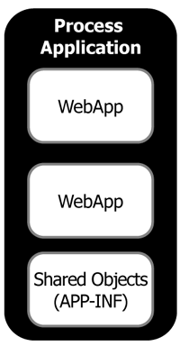
Each web application consists of the following items:
The input JMS queues use an optimized, internal format for messages. They are used implicitly by WebLogic Integration and WebLogic Platform components including process controls, Message Broker, buffered messages, and so on.
| Note: | These input queues are not intended to be used directly by applications. If you are looking for a JMS queue that can be used directly by an application, consider the WebLogic Workshop SOAP/JMS protocol or the WebLogic Integration JMS Event Generator. |
| Note: | For more information about the SOAP/JMS protocol, see Workshop For WebLogic Platform Programmer's Guide. For more information about the JMS Event Generator, see Event Generators in Using The WebLogic Integration Administration Console. |
This is used for dispatching exception elements in process definition.
Figure 1-2 shows the components in a process web application.
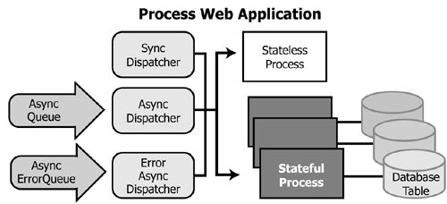
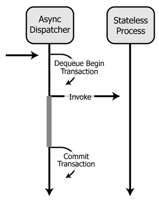
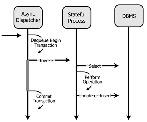
The asynchronous dispatcher has different interactions with stateless and stateful processes. For an illustration of the interaction between the asynchronous dispatcher and a stateless process (see Figure 1-3).
For an illustration of the interaction between the asynchronous dispatcher and a stateful process (see Figure 1-4).
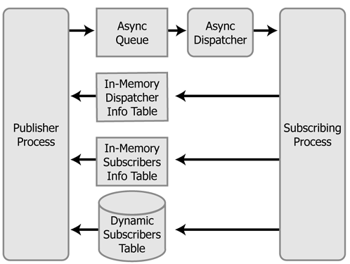
The process control allows messages to be sent directly from one process to another, either through RMI or through JMS using an optimized data format. Normal WebLogic Server load balancing rules apply when using RMI or JMS. (Typically the message will stay on the same server in a cluster due to server affinity of WebLogic Server load balancing.)
An in-memory dispatcher table provides the detailed information needed by the process control to send the message at run time. This dispatcher table is automatically updated when an application is deployed or redeployed.
The behavior of a process call depends on whether it is being used for a synchronous or asynchronous dispatch. The following figure shows the behavior of a process control used for a synchronous dispatch (see Figure 1-5).
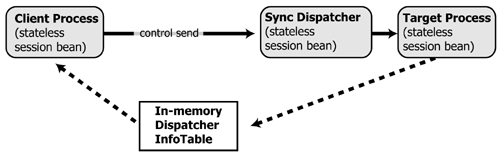
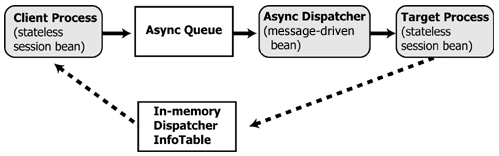
Figure 1-6 shows the behavior of a process control used for an asynchronous dispatch.
It is also possible for a synchronous client process to interact with an asynchronous process.
| Note: | You can optimize performance of this configuration by creating the following dedicated execution thread pools: |
| Note: | Choose a thread pool size that matches the requirements of your application and tracking level. |
| Note: | If you do not create these pools, threads will be consumed from the default thread pool. For more information about execution thread pools. |
For more information about this configuration, see Synchronous Clients for Asynchronous Business Processes in "Building Synchronous and Asynchronous Business Processes" in the "Guide to Building Business Processes". For implementation examples, see the WebLogic Integration Solution Samples.
Any time the Message Broker publishes a message through a Message Broker publish control or event generator, the following actions occur:
The Message Broker uses the same JMS asynchronous queue that the process control uses. Once a message is enqueued, it follows the same code path as if it were sent using the process control. For more information about publishing using the Message Broker control (see Figure 1-7).
WebLogic Integration has a number of native event generators:
In addition, event generators are used for application integration EIS events. (For additional information regarding event generators for EIS adapters, see Application Integration Capabilities and Clients).
The JMS event generator is packaged as a message-driven bean pool. It can be targeted freely to any number of managed servers in a cluster. It would typically be targeted to either a single managed server when using a physical JMS destination, or to the cluster when using distributed destinations.
These event generators are "polling" event generators, in that they poll for events to happen. To do this, each event generator is packaged as a message-driven bean pool and configured with a specific JMS queue. Messages are sent from the event generator to its associated queue with a delivery time of poll-interval in the future. The queue is shared between event generators of the same type (file, email, and so on), and a selector is used to share messages in the queue.
How you target a polling event generator depends on how the JMS server owning the associated queue has been targeted, as shown in the following table.
Because the polling event generators would contend with each other during their polls, they are restricted to being active on a single managed server in a cluster. When an event generator is associated with a migratable queue, it is active only on the single server containing the migratable JMS server—even though the polling event generator is targeted to the cluster.
| Note: | WebLogic Integration supports polling event generators targeted to a single server. However, this configuration is not appropriate for applications that require high availability. |
The HTTP event generator is a servlet which takes HTTP requests, checks for the content type, and then publishes the messages to Message Broker channels. The MQSeries event generator polls for messages on a WebSphere MQ queue and publishes the messages (MQMD headers as metadata along with the message payload) to Message Broker channels. Content filtering, as well as other handling criteria, are specified in the channel rules for the event generator. Both the HTTP and MQSeries event generators can be targeted to a single managed server or cluster, as described in the Event Generators section of Using The WebLogic Integration Administration Console.
The RDBMS event generator polls the database table to check for added, deleted, or updated rows and publishes the results to Message Broker channels. You can also use this event generator to run custom queries on the database table and publish the results to Message Broker channels, as described in the Event Generators section of Using The WebLogic Integration Administration Console.
It is important to note that the suspended status of an event generator is not preserved when the server is restarted. If the event generator is in the suspended state when the server is restarted, the event generator remains suspended and no events are processed. You can restart the event generator by setting it to `running' from the WebLogic Integration Administration Console. For more information, see the Event Generators section of Using The WebLogic Integration Administration Console.
Trading Partner Integration (TPI) provides a framework for peer-to-peer business protocols, implementing RosettaNet (versions 1.1 and 2.0) and ebXML (versions 1.0 and 2.0).
| Note: | Trading Partner Integration was formerly known as B2B. Some resource names contain abbreviations that are a legacy from prior WebLogic Integration releases. The Trading Partner Integration resources currently retain B2B as part of their names |
When you deploy WebLogic Integration to a clustered domain, all Trading Partner Integration resources—with the exception of resources for the administration server—must be deployed homogeneously in the cluster. Targeting Trading Partner Integration resources to all clustered servers in a domain enables you to achieve high availability, scalability, and performance improvements for your application.
For more information about Trading Partner Integration resources and clustering, see Designing a Clustered Deployment. For information about resources that can be configured to accommodate Trading Partner Integration loads, see Trading Partner Management in Using The WebLogic Integration Administration Console.
The Trading Partner Management Repository is an important part of Trading Partner Integration. Database operations on this repository and for all of Trading Partner Integration are performed through the JDBCTxDataSource named cgDataSource using the JDBCPool named cgPool.
| Note: | You can configure the database for your Trading Partner Management Repository to use concurrent access. For information about issues regarding specific databases, see the WebLogic Integration 9.2 Release Notes. |
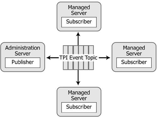
Data from the Trading Partner Management Repository is cached during server startup to improve performance by reducing access to this resource. In a cluster environment, the Trading Partner Management Repository data is cached on the administration server and each managed server. These caches are synchronized through the mechanism shown in Figure 1-8.
The WebLogic Integration Administration Console enables you to perform updates, imports, and deletions to the Trading Partner Management Repository. For information about using the WebLogic Integration Administration Console to perform these operations, see Trading Partner Management in Using The WebLogic Integration Administration Console.
Trading Partner Integration is initialized during server startup by the WLI-B2B Startup EJB.
| WARNING: | The WLI-B2B Startup EJB has an initial-beans-in-pool setting of 1. Changing this value will cause Trading Partner Integration startup to fail. |
At run time, outgoing and incoming Trading Partner Integration messages traverse different paths. The following sections describe the paths and process flows for outgoing and incoming business messages.
Figure 1-9 shows the path of an outgoing business message.
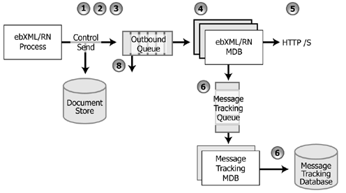
The preceding figure illustrates the following process flow:
wli.internal.b2b.rosettanetencoder.queue and wli.internal.b2b.ebxmlencoder.queue, respectively.wli.internal.msgtracking.queue. The WLI Message Tracking message-driven bean listens to this queue. It will update the various message tracking tables based on the tracking level set in the Trading Partner Management module of the WebLogic Integration Administration Console.For information about using the WebLogic Integration Administration Console to set tracking levels, see Trading Partner Management in Using The WebLogic Integration Administration Console.
Figure 1-10 shows the path of an incoming business message.
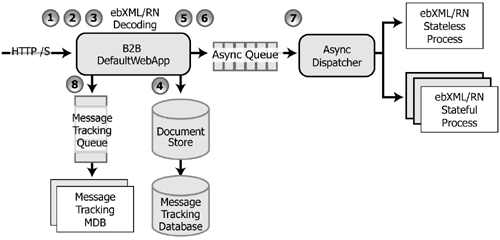
The preceding figure illustrates the following process flow:
B2BdefaultWebApp/WEB-INF/web.xml. The filter inspects the URL and decides if the incoming request is a TPI URL / request. If it is not destined for Trading Partner Integration, the message continues on to other filters and the final destination servlet.b2b.war. wli.internal.msgtracking.queue. The WLI Message Tracking message-driven bean listens to this queue. It will update the various message tracking tables based on the tracking level set in the Trading Partner Management module of the WebLogic Integration Administration Console.For information about using the WebLogic Integration Administration Console to set tracking levels, see Trading Partner Management in Using The WebLogic Integration Administration Console.
The following sections describe the major capabilities of WebLogic Application Integration and how clients make use of those capabilities:
For information about clustering and application integration, see Understanding WebLogic Integration Clusters.
Application integration functionality is integrated in the WebLogic Integration product. In order to use application integration with other components of the WebLogic Platform (such as WebLogic Workshop or WebLogic Portal) you must configure a domain that includes each of those components. For information about creating domains, see Creating a New WebLogic Domain in Creating WebLogic Configurations Using the Configuration Wizard. For more information about deploying WebLogic Platform applications, see Deploying Applications to WebLogic Server.
Use synchronous invocations when the underlying EIS can respond quickly to requests, or when the client application can afford to wait.
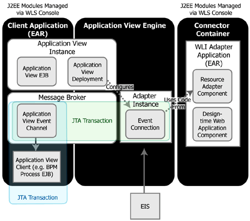
Figure 1-11 illustrates the flow of a synchronous service invocation.
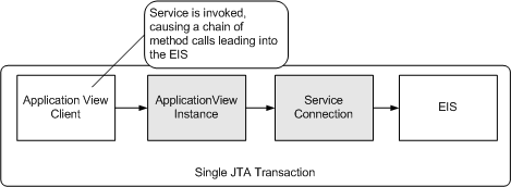
In a synchronous service invocation, a client (for example, a business process) calls the application view (for example, as a control in the business process). The application view calls the adapter using a synchronous Common Client Interface (CCI) request. The service adapter is a J2EE-CA service adapter that actually processes the request.
| Note: | When a process acts as a client to an EIS, the process is stalled while it waits for the request to complete, tying up a WebLogic execute thread, business process, EJB instances, and other resources. To optimize throughput, consider using asynchronous invocations instead unless the underlying EIS system can respond quickly to the request. |
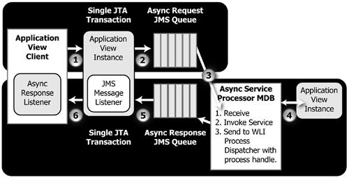
Figure 1-12 illustrates asynchronous service processing in WebLogic Integration.
| Note: | When using the Application View control from a WebLogic Integration process or WebLogic Workshop Web service, the asynchronous response is delivered directly to the EJB for the process or Web service without being posted to the asynchronous response JMS queue. |
Figure 1-13 shows the processing that takes place during asynchronous service invocations in a WebLogic Integration process client.
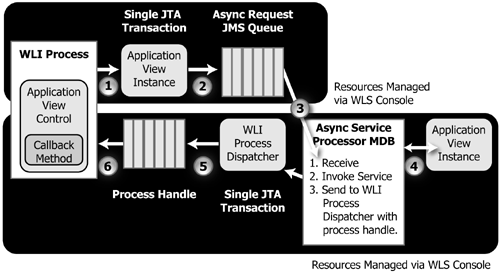
The preceding diagram illustrates the following process flow:
AsyncServiceRequest object and sends it to the wli.internal.ai.async.request queue. AsyncServiceProcessor message-driven bean receives the message from the queue in a first in, first out (FIFO) manner. The AsyncServiceProcessor uses the AsyncServiceRequest object in the JMS ObjectMessage to determine the qualified name, service name, request document, and response destination for the application view.AsyncServiceProcessor uses an application view EJB to invoke the service synchronously. The service is translated into a synchronous CCI-based request/response message for the resource adapter.AsyncServiceProcessor receives the response. The response is subsequently encapsulated into an AsyncServiceResponse object and sent to the response destination provided in the AsyncServiceRequest object:onServiceNameResponse) on the ApplicationView control instance. AsyncServiceResponse message as a JMS ObjectMessage and passes it to the AsyncServiceResponseListener supplied in the invokeServiceAsync() call shown in
step 2Application integration adapters generate events that are consumed by business processes or Web services. Events are then delivered to application view clients through one of two methods:
MessageBroker event channel (named for the ApplicationView and event type for the event).EventListener object provided by the client. The event is actually delivered to the EventListener through a JMS topic and JMS MessageListener instance (provided by the ApplicationView instance) on that topic.Figure 1-14 illustrates event processing in WebLogic Integration.
The preceding figure illustrates the following sequence of steps for event processing:
IEvent object to all registered ApplicationView event subscription objects that have indicated interest in this event type. Subscription objects are registered at application view deployment time.IEvent object to both the MessageBroker event channel for the event type (named for ApplicationView/event) and the wli.internal.ai.event JMS topic.WebLogic Integration relies extensively on database resources for handling run-time operations and ensuring that application data is durable. Database performance is a key factor in overall WebLogic Integration performance. For information about database tuning requirements associated with WebLogic Integration applications, see Preparing Your Database and the database-specific notes in Maintaining Availability.
For additional information on turning your database, see your database vendor's documentation.
Hardware, operating system, and network resources play a crucial role in WebLogic Integration performance. Deployments must comply with the hardware and software requirements described in the WebLogic Integration 9.2 Release Notes.


|