6 Managed Networks
The following topics are described in this chapter.
About Managed Networks
Enterprise Manager Ops Center manages networks for its virtual hosts. Guests in the network communicate with each other or with the Internet through these virtual hosts. The networks are defined only within Enterprise Manager Ops Center so you cannot manage the network connections for servers and chassis.
You can use networks to do the following:
-
Manage individual hosts
-
Connect hosts to the Proxy Controller
-
Allow guests to communicate with each other or with the Internet
-
Connect remote JMX with the public API
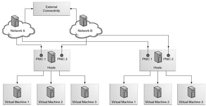
A managed network depends on the physical network interface card (PNIC) that is available the host. You can create one managed network for each physical network interface card. If one host has two PNICs, it is a good practice to create two managed networks: a management network and a data network. This configuration lets you place all the guests on the data network, keeping them separated from the management network, which gives access to internal resources of the data center.
The following configuration shows how two hosts participate in two managed networks. The actual network connection is made to the PNICs in the virtual host. Network A is connected to PNIC 1 of both hosts and Network B is connected to PNIC 2 of the hosts.
See Virtual Pools and Networks for information about virtual pools and networks.
About IPMP Groups and Aggregated Links
You can create managed networks that use IPMP groups. In IPMP, two or more physical network interface cards (NIC) form an IPMP group and use the same IP Address. If one NIC fails, another NIC in the group can maintain network access. You can also create managed networks that use link aggregation. In an aggregated link, two or more NICs form a group and all members of the link aggregation provide network access at the same time. While both methods provide high availability and load balancing, an aggregated link can also provide increased throughput if the network ports are also aggregated. You can implement both methods on the same network because they work at different layers of the network stack. See Additional Resources for links to the Oracle Solaris documentation for these services, which explains how to implement IPMP and link aggregation.
About IPMP Groups
IPMP (IP network multipathing) provides increased reliability, availability, and network performance for systems with multiple physical interfaces. It provides physical interface failure detection and transparent network access failover.
Occasionally, a physical interface or the networking hardware attached to that interface might fail or require maintenance. By using IPMP, you can configure one or more physical interfaces into an IP multipathing group, or IPMP group. After configuring IPMP, the system automatically monitors the interfaces in the IPMP group for failure. If an interface in the group fails or is removed for maintenance, IPMP automatically migrates, or fails over, the failed interface's IP addresses. The failover feature of IPMP preserves connectivity and prevents disruption of any existing connections.
You can create networks that includes IPMP groups. The association between an IPMP group and a network must be unique; an IPMP group can be associated with only one network and a network can be associated with only one IPMP group or individual NICs.
In an IPMP group, you define whether each interface is a failover or a standby one. The actions of each type differ if the current network interface fails:
-
Network access changes from the failed interface to the failover interface in the IPMP group and uses the failover interface data address. You must provide the data address for an interface that is defined as failover.
-
Network access changes from the failed interface to the standby interface in the IPMP group but does not change its data address. The data address of the failed interface migrates to the standby interface.
Link-based failure detection in an IPMP group is always enabled if your interface supports this type of failure detection. You can also set for probe-based failure detection by providing a test address for each interface in the group.
You can create IPMP groups while provisioning OS. You can create only one IPMP group while provisioning an OS. If you create IPMP groups manually, Enterprise Manager Ops Center identifies and displays the groups on the UI.
IPMP Groups and Global Zones
A network that has an IPMP group can be assigned to a global zone. You can assign the network to the global zone and select the IPMP group from the list of interfaces. After you finish the configuration, the network details for the global zone displays the members of IPMP group that are now associated with the network.
If you need to remove a NIC from the IPMP group, you must first verify that the global zone is not using the NIC. If the zone is using the NIC, you must stop the zone, detach the network from the zone, and then re-attach the network using a different NIC in the IPMP group. If you remove a NIC from the IPMP group while the zone is using it, the zone continues to function but the NIC is not able to communicate with the network.
Note:
When Enterprise Manager Ops Center discovers and manages a brownfield zone that has a network with an IPMP group, it does not detect the IPMP group and represents the NICs individually.Shared IP Zones With IPMP Groups
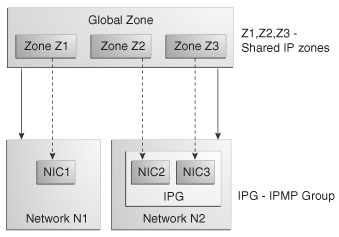
When you create a shared IP zone on a network associated with an IPMP group, all the available interfaces of the group will be displayed on the UI except the failed and standby interfaces. The IPMP groups are not detected for shared IP zones and the available interfaces of the groups are presented directly for association. The shared IP zones use the interfaces individually and not as a group.
For example, the global zone is GZ associated with network N1 and N2 which is in shared IP mode. N2 has the IPMP group IPG. IPG consists of NIC2 and NIC3. GZ has three shared IP zones z1, z2, and z3. Zones z1, z2, and z3 are connected to the shared IP network N1 and N2. z2 and z3 can be connected through NIC2 and NIC3 of the IPMP group and zone z1 through the NIC1 of network N1.
The connection of shared IP zones to a network with IPMP groups is described in the following illustration.
Exclusive IP Zones With IPMP Groups
For an exclusive IP zone, you can connect to a network multiple times. You can then manually define the IPMP group in the exclusive IP zone.
IPMP Groups and Oracle VM Server for SPARC
For a logical domain, you can associate a network multiple times on the same Oracle VM Server. The multiple connections are made through different switches on the Oracle VM Server. Each switch can connect to only NIC at a time.
Connecting a logical domains multiple times to a network on the same Oracle VM Server will allow to create IPMP groups in the logical domains. You can create and define the IPMP groups in the logical domains.
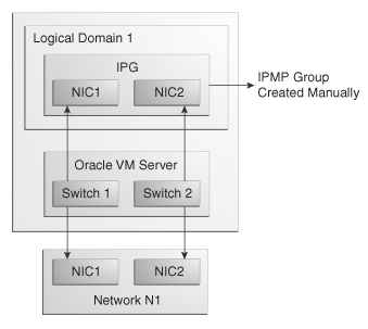
There is a naming pattern for the switches that are created in Oracle VM Server. If an Oracle VM Server is connected to a network, for an example network 1.1.1.0/24, the name of the virtual switches will be 1.1.1.0_24, 1.1.1.0_24_1, 1.1.1.0_24_2 and 1.1.1.0_24_3. When a network connection is made to the Oracle VM Server, the virtual switch created is incremented.
Each virtual switch created has to be connected to an interface. You can then define the IPMP groups in the logical domains with the connected interfaces to it. The network connections with IPMP group is described in the following illustration.
Figure 6-3 Network Connections with an IPMP Group
Description of "Figure 6-3 Network Connections with an IPMP Group"
About Link Aggregation
Link aggregation is a standard defined in IEEE802.3ad. An aggregated link consists of several interfaces on a system configured as a single, logical unit. Link aggregation increases the speed and high availability of a connection between a server and a switch. The most common protocol used to manage link aggregation is LACP (Linked Aggregation Control Protocol). See Additional Resources for more information about link aggregation.
You can create a link aggregation while provisioning an OS. You can configure the interfaces together as a logical unit and define the link aggregation information if the following conditions are met:
-
All the members of the aggregated link are connected to the same switch.
-
The members of the aggregated link are of the same type. For example, NICs with the e1000g interface cannot be mixed with NICs that use the bge interface.
-
For Oracle Solaris OS, the required driver is GLDv3.
Note:
You can create only one link aggregation while OS provisioning. Enterprise Manager Ops Center displays the link aggregation that are created manuallyWhen interfaces have been aggregated, they are treated as a single network interface. Enterprise Manager Ops Center displays the link aggregation in the list of available NICs as if it were an individual interface. When you assign a network with a link aggregation to an Oracle VM Server, logical domain, global zone, or a non-global zone, select the link aggregation from the NIC list. You can view the link aggregation details on the Oracle VM Server's or global zone's Network tab.
Viewing a Managed Network's Configuration
Use the tabbed pages in the center pane to learn about a managed network.
-
Expand Managed Networks in the Navigation pane.
-
Select the network you want to view. The Dashboard page is displayed. The Summary section shows the attributes that were specified when the network was created or last modified and also includes a set of Problem icons for the network.
-
For detailed information about problems, scroll down to view the Status table.
-
For detailed information about all problems, click the Problems tab.
-
For information about what values are being monitored, click the Monitoring tab. The Membership Graph section shows the relationship of the selected network to other Ops Center assets. For detailed information about these network objects, click the Network Connections tab.
-
-
Click the Network Details tab. This page repeats the information in the Summary tab and also lists the static routes that have been defined for the network.
-
Click the Network Services tab to show the services that have been specified for this network. To change any services, use the procedure in Editing Network Services.
-
Click the Network Connections tab to see a table of all the virtual pools that this network is assigned to and all the guests assigned to this network.
To change some of the network information, see the procedure in Editing Network Attributes.
Viewing the Virtual Hosts and Guests Using a Network
Use the following procedure to display the guests that use a specific network.
-
Expand Managed Networks in the Navigation pane. A list of physical networks is displayed.
-
Select a network.
-
Click the Network Connections tab. A table of virtual pools is displayed with the virtual hosts in the virtual pools.
-
Expand each virtual pool and virtual host to see all the guests.
The management IP address and MAC address of each virtual host that is using the network is displayed. The IP address and MAC address of each guest that is using the network is displayed.
Virtual Pools and Networks
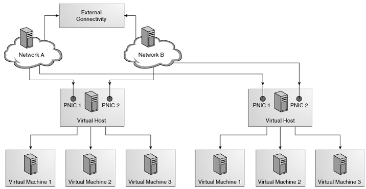
In Enterprise Manager Ops Center, networks are associated with virtual pools so even a standalone virtual host is considered a virtual pool with one member. However, most virtual pools have more than one virtual host. When you assign a network to a virtual pool, the network is accessible to all virtual hosts in the pool and every guest of each virtual host can use the network.
A virtual pool must have at least one associated network. When associate more than one network with a virtual pool, all virtual hosts in the virtual pool are associated with the same set of networks. When you add a virtual host to a virtual pool, the virtual host is configured for all the virtual pool's associated networks. The virtual host has access to all the networks defined for the pool and can be an active member of the pool. This ensures that all guests have access to the network if you migrate a guest from one virtual host to another one within the pool.
The following figure illustrates the view for network connections to two virtual hosts in a virtual pool. This virtual pool has two virtual hosts and two network associations.
See Viewing the Virtual Hosts and Guests Using a Network.
Viewing a Virtual Pool's Networks
Use the following procedure to display the networks of the virtual hosts in a virtual pool.
To View a Virtual Pool's Networks
-
Expand Assets in the Navigation pane.
-
Expand Virtual Pools.
-
Select the virtual pool.
-
Click the Network tab. A table of the virtual hosts in the virtual pool in displayed.
-
Expand each virtual host to see all the guests.
The management IP address and MAC address of each virtual host that is using the network is displayed. The IP address and MAC address of each guest that is using the network is displayed.
Assigning a Network to a Virtual Pool
When you create a network, you use the Manage Network wizard to assign the network to virtual pools. Use this procedure to assign the network to a different virtual pool.
To assign a network to a global zone, see Assigning Networks to a Global Zone in the Oracle Enterprise Manager Ops Center User's Guide.
To Assign a Network to Virtual Pools
-
From the Navigation pane, click Managed Networks. A list of physical networks appear under the Managed Networks section.
-
Select a network from the list of networks.
-
Click Assign Network. The Assign Network to Virtual Pool wizard is displayed.
-
In the Select Virtual Pools step, select the virtual host or virtual pool to which you want to assign this network. Click Next.
-
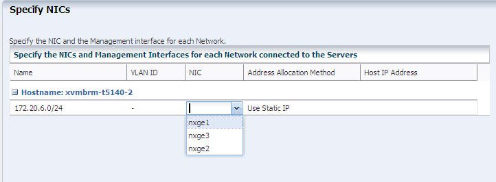
In the Specify NICs screen, identify the network connection and its management interface.
The NIC drop-down list displays all the available NICs and link aggregations. For each host, specify the network connection. For the Address Allocation Method, choose to use either a static IP address or an IP address assigned by DHCP.
-
For a static IP address, type the IP address in the Host IP Address field.
-
For a dynamic IP address, type the IP address of the DHCP server in the Host IP Address field. Click Next.
-
-
Review the selections that you made.
-
Click Save.
Changing the Routing Mode
A virtual host uses the network assigned to it according to the host's routing mode. You specify a virtual host's routing mode during its initial configuration if you do not accept the default mode, Automatic Routing. Enterprise Manager Ops Center supports the following routing modes:
-
Automatic Routing This is the default routing mode. Applying the static routes depends on the following conditions:
-
If a default gateway or static route is defined by the user or retrieved from the DHCP server, this route is used and dynamic routing is disabled.
-
If no default gateway or static route is available, dynamic routing is enabled.
-
-
Dynamic Routing Off The virtual host uses the default gateway and any static routes configured for the network. The default gateway is retrieved from the DHCP server.
-
Dynamic Routing On The virtual host uses routes provided by the dynamic routing service. The default gateway and any static routes configured for the network are ignored.
To Change the Routing Mode of a Virtual Host
-
From the Assets pane, select Virtual Pools.
-
Select the virtual pool that contains the virtual host for which you want to change the routing mode.
-
Select the Summary tab.
-
Select a virtual host from the table.
-
Click the More Actions drop-down list in the table.
-
Click Change Routing Configuration.
-
Specify the routing mode that you want to set.
Specifying the Maximum Transmission Unit (MTU)
The default size for the network's Maximum Transmission Unit (MTU) is 1500 bytes. If your network interface card is one of the following types, you can change the size of the MTU to a size between 576 and 9216 bytes:. However, to assign the network to a logical domain, the minimum MTU size is 1500 bytes.
nxge
ixgbe
hxge
e1000g
ce
bge
ipge
When you specify a size greater than 1500 bytes, Enterprise Manager Ops Center modifies the network interface card's MTU size. For other types of network interface cards, the MTU is changed when the card's driver firmware is updated to support the new MTU size. However, to change the MTU value for an IPMP group, you must edit the MTU value manually.
When you assign the network to a virtual host, complete the following tasks so that the network's MTU size takes effect.
Note:
This procedure succeeds when the Oracle VM Server's switch was created using Enterprise Manager Ops Center 11 g. It is not possible to change the MTU size for a switch created with previous versions of the software.-
For a network with an MTU greater than 1500 bytes that is assigned to an Oracle VM Server, change the Oracle VM Server's switch's MTU manually to accommodate the network's MTU size, using the following command:
ldm set-vswitch mtu=<value> <vswitchname>
For example, to change the MTU of 192.192.192.0_24 to 4000, use the following command:
ldm set-vswitch mtu=4000 192.192.192.0_24
-
Reboot the global zone or Oracle VM Server assigned to the network. If you change the MTU of a network assigned to a logical domain, stop and restart the logical domain.
Note:
When you provision an OS, the MTU size resets to the default value. You must change the MTU again after you provision the system.Dissociating a Network from a Virtual Pool
Use the following procedure to disconnect a network from a virtual pool.
To Dissociate a Network from a Virtual Pool
-
Select the appropriate virtual pool.
-
From the Assets pane, select Virtual Pools.
-
Select the virtual pool.
-
Click the Networks tab.
-
Select the network that you want to dissociate from the virtual pool.
-
Click the Unbind Network in the Action pane. The network is no longer assigned to the virtual pool.
Creating a Network
Use the following procedure to create a new network.
You must have a physical network interface card that is not used. You can also specify a link aggregation.
The mandatory network parameters are:
-
IP address of the network
-
Netmask
-
If you use static IP addressing, the IP address of the management interface
-
If you use dynamic IP addressing, the range of allowed IP addresses and the gateway address
-
Expand Managed Networks in the Navigation pane.
-
Click Manage Network in the Actions pane. The Manage Network wizard opens.
-
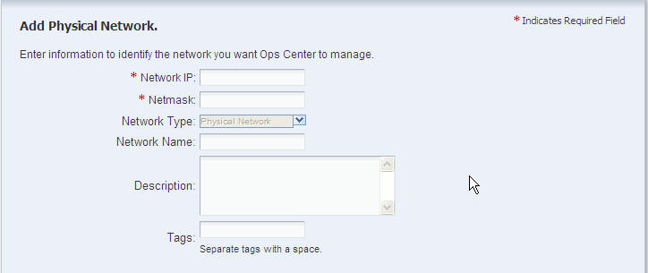
In the Identify Network screen, type the IP address of the network and netmask.
Type the network name, description, and tags for the network. Click Next.
-
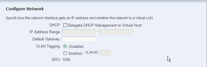
In the Configure Network screen, choose whether to use a DHCP server to assign IP addresses.
Type the range of IP addresses for the network in the Assignable IP range field. Type the default gateway address in the Default Gateway field. MTU specifies the size of the packet in bytes. The default size is 1500 bytes. Click Next.
-
In the Specify Static Routes screen, add the static routes for the network. However, the static routes and the default gateway are not used if the host uses Dynamic Routing mode. Type the destination IP, netmask, and the default gateway. If you want to add additional static routes, click Add and type the required information. Click Next.
-
In the Specify Network Service screen, specify the time server, WINS, DNS, and NIS services for the guests. This information configures the DHCP server, if DHCP support has been enabled. Type the NIS domain name before typing NIS servers. However, you can type the DNS servers without typing a DNS domain name. Click Next.
-
In the Assign Network screen, select the virtual pools or virtual hosts.
Note:
Although this screen includes global zones, you cannot select them. To assign a global zone to this network, use the procedure in Assigning Networks to a Global Zone after you complete this procedure. Click Next. -
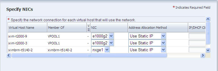
In the Specify NICs screen, attach one or more hosts to the network.
For selected virtual host, identify its network connection and its management interface.
-
The NIC drop-down list displays all the available NICs and link aggregations. For each host, specify the network connection.
-
For the Address Allocation Method, choose to use either a static IP address or an IP address assigned by DHCP.
-
For a static IP address, type the IP address in the IP/DHCP Client ID field.
-
For a dynamic IP address, type the IP address of the DHCP server in the IP/DHCP Client ID field.
-
Click Next.
-
-
In the Summary screen, review the network specifications. Click Finish to create the new network. The new network is listed in the Managed Networks section.
When you have finished creating a network, you can assign this network to serve a virtual pool, as described in Assigning a Network to a Virtual Pool , or connect guests in the host to this network, as described in Connecting Guests to a Network.
Adding and Modifying VLAN Tags
The ability to use VLAN tags is an attribute of each managed network. Use the Edit Network Attributes action to add or change the VLAN capability.
To Edit the Network Attributes for VLAN
-
Expand Managed Networks in the Navigation pane.
-
Select a network from the list of networks.
-
Click Edit Network Attributes in the Actions pane or click the Edit icon in the center pane.
-
Click Enabled to activate VLAN tagging.
-
To add a VLAN tag, type the tag in the VLAN Tags field. Separate a series of tags with commas.
Adding a Static Route for the Network
Static routes specify the route that must be taken by the network to have external access. Although you define a default gateway for a managed network, it might not reach a particular subnet. In this case, you must also provide a static route for the subnet.
When you create a network, you can specify the static route. To add static routes after the network has been created, use the following procedure.
To Add a Static Route for the Network
-
Click Managed Networks in the Navigation pane.
-
Select a network from the list of networks.
-
Click Edit Network Attributes in the Actions pane.
-
Click the Add icon in the Static Routes table. A row is added to the table.
-
Type the values for destination IP, netmask, and gateway.
-
To modify an existing static route, click the route and change the value in the field.
-
Click Finish.
You can delete a static route and change the order of the routes using the icons in the Static Routes table.
Editing Network Attributes
The characteristics of a managed network are displayed in its Network Details tab. You can edit the network name and description, MTU size, assignable IP range, and default gateway. The network IP address, netmask, and its network type cannot be changed. You can also enable and disable DHCP service, VLAN tagging, and manage the static routes of the network. To change the MTU size, see the instructions in Specifying the Maximum Transmission Unit (MTU).
To Edit the Network Attributes
-
Expand Managed Networks in the Navigation pane.
-
Select a network from the list of networks.
-
Click Edit Network Attributes in the Actions pane.
-
Modify the values of the network attributes. Network name cannot be empty.
-
Click Finish.
If you changed the MTU value, also change the virtual host's MTU value and reboot.
Editing Network Services
The network services that a managed network provides are shown on its Network Services tab: time server, WINS, DNS, and NIS. To modify these services, edit the network services. You cannot change the network's IP address or name.
-
Expand Managed Networks in the Navigation pane.
-
Select a network from the list of networks.
-
Click Edit Network Services in the Actions pane. The Edit Network Services window shows the current definition of the network's services.
-
For either Time Server or WINS, enter the IP address of the server for that service. For DNS or NIS, you can edit the IP address of the current server, add an alternate server, delete a server, or change the order of the servers. Use the icons in each table to configure the network service.
-
Click Submit.
Deleting a Network
When you delete a managed network, any assigned resources such as a DHCP server are released from the network.
Note:
You cannot delete the last network.Verify that the network you want to delete is not associated with any virtual pool and not connected to any guest.
-
Expand Managed Networks in the Navigation pane.
-
Select the network you want to delete.
-
Click Delete Network in the Actions pane. The Delete a Network window is displayed, showing the IP address and name of the network you selected.
-
Click Delete Network.
Connecting Guests to a Network
The guests of a virtual host can use the network that is assigned to the virtual host or to the virtual pool to which the virtual host belongs. Each guest must be connected to a network. Use this procedure to connect a disconnected logical domain.
Stop the guests and verify they are in stopped state.
To Connect Guests to a Network
-
Expand Managed Networks in the Navigation pane.
-
Select the network to which you want to connect guests.
-
Click Connect Guests in the Actions pane.
-
The Connect Guests to Network window is displayed, including a table of guests that are not connected to a network.
Figure 6-9 Connecting Guests to a Network
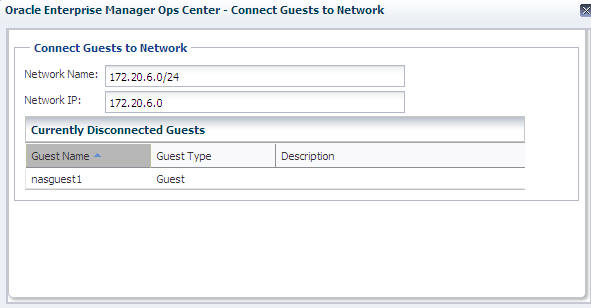
Description of "Figure 6-9 Connecting Guests to a Network"
Note:
Zone guests are not displayed in this table. -
Select one or more guests from the table.
-
Click Connect Guests. A new connection between the guest and the network is created.
-
When the job is completed, re-start the guest.
Disconnecting a Guest From a Network
The guest you want to disconnect must be in the stopped state. You can disconnect a guest from a network in two ways.
To Disconnect a Guest From a Network
Use the following procedure to disconnect a guest from its network.
-
Expand Managed Networks in the Navigation pane.
-
Select a network from the list of networks.
-
Select the Network Connections tab.
-
Select the logical domain or non-global zone that you want to disconnect.
-
Click the Disconnect Guest icon. The Disconnect Guests From Network pop-up window appears.
-
Click Disconnect Guests.
The guests that are disconnected from the network are removed from the Network Connections table of the network.
-
Expand Assets in the Navigation pane.
-
Select a logical domain or a non-global zone.
-
Select the Network tab.
-
Select a network from which you want to disconnect the guest.
-
Click the Disconnect Guest From Network icon. The Unbind a Network pop-up window appears.
-
Select the network from the pop-up window.
-
Click Disconnect From Network. The guests that are disconnected from the network are removed from the Network Connections table of the network.