7.3 Management Network Diagram for Exalogic Machine
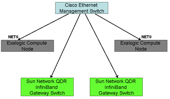
Figure 7-1 illustrates the management/ILOM network in the Exalogic machine.
Figure 7-1 Management Network in Exalogic Machine

Description of "Figure 7-1 Management Network in Exalogic Machine"
Figure 7-1 shows two compute nodes and two Sun Network QDR InfiniBand Gateway Switches as an example only. The number of compute nodes and gateway switches depends on your purchased Exalogic machine rack configuration. The Cisco Ethernet management switch is connected to the NET0 port of compute nodes, and it is connected to the InfiniBand gateway switches.