8.4 Configuration Overview
The storage appliance in the Exalogic machine is configured at different stages of the Exalogic machine setup and enterprise deployment.
The following are the configuration stages:
8.4.1 Initial Configuration
The initial configuration involves networking configuration for the NET0 interface, configuration of ILOM IP addresses, launch of service processor console, launch of several client network services, and the layout of the storage pool for standalone operation. When completed, the appliance in the Exalogic machine is ready for use, and it will have default shares configured for Exalogic compute nodes to access.
Note:
When you run the Oracle Exalogic Configuration Utility set of tools and scripts, the initial configuration for the storage appliance is completed.
For more information, see the Shares and Configuration sections of the Oracle ZFS Storage Appliance Administration Guide (http://docs.oracle.com/cd/E27998_01/html/E48433/toc.html). Alternatively, see the Oracle Fusion Middleware Exalogic Enterprise Deployment Guide for the recommended storage configuration in the Oracle Exalogic environment.
8.4.2 Connect Storage Heads to the Management Network and Accessing the Web Interface
Figure 8-1 shows the physical network connections for the storage appliance.
Figure 8-1 Network Ports on the Storage Appliance
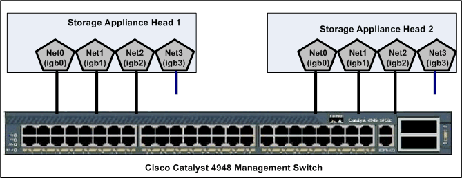
Description of "Figure 8-1 Network Ports on the Storage Appliance"
By default, the NET0 (igb0), NET1 (igb1), and NET2 (igb2) ports on the storage heads are connected to the Cisco management switch, which is included in the Exalogic machine. The igb0 and igb1 interfaces are reserved for administrative access, such as access via a web browser or via command line. This configuration ensures that the storage heads are always reachable, independent of the load on the network data interfaces, and independent of which head is active. One end of a free hanging cable is connected to NET3 (igb3). You can use the other end of this cable to connect to your data center network directly. Typically, for high availability purposes, this cable is connected to a data center switch other than the one that Exalogic's Cisco Management Switch is connected to.
To view the default network configuration of the storage appliance included in your Exalogic machine, do the following:
8.4.3 Cluster Network Configuration
The cluster is set up in an active-passive configuration. All resources, data interface links, and storage pool are owned by the active storage head. When the active node fails, all resources (except the one that is locked to the active node) will be taken over by the passive storage head.
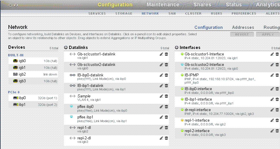
In the example configuration for an active head, igb0 is used as the administrative network interface for the active storage head, such as storagenode1. The lock symbol indicates that igb0 is locked to this storage head. To access this active storage head in a browser, you can use the following URL using either the host name or the IP address:
https://storagenode1:215
or
https://<IP_storagenode1>:215
In the example configuration for a passive head, igb1 is used as the administrative network interface for the passive storage head, such as storagenode2. The lock symbol indicates that igb1 is locked to this storage head. To access this passive storage head in a browser, you can use the following URL using either the host name or the IP address:
https://storagenode2:215
or
https://<IP_storagenode2>:215
Note:
For more information about network configuration for the storage appliance, see the Network topic in the Oracle ZFS Storage Appliance Administration Guide.
8.4.4 Network Configuration Options
You can choose any of the following network configuration options for the storage appliance, based on your specific requirements:
8.4.4.1 Configure Option 1: ASR Support and Separate Paths for Management and Disaster Recovery
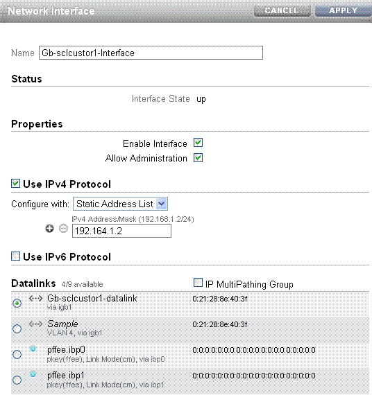
In this default configuration, the igb0 port on your active storage head (head 1) is used, and the management option is enabled. The igb0 port on your stand-by storage head (head 2) is not used. The igb1 port on your stand-by storage head (head 2) is used, and the management option is disabled. The igb2 and igb3 ports are bonded with IP Multipathing (IPMP), and the management option is disabled on both igb2 and igb3.
Tip:
Administrators should remember to use two different management URLs for the storage heads.
This default configuration option offers the following benefits:
-
Supports Automated Service Request (ASR) for the storage appliance included in the Exalogic machine, using ports
igb0andigb1 -
Supports disaster recovery for the Exalogic machine, using ports
igb2andigb3 -
Provides Exalogic Configuration Utility, which is used to reconfigure the Exalogic machine based on your specific requirements, with ports
igb0andigb1 -
Separates the disaster recovery path from the management path
Note:
Ensure that the free hanging cable from the igb3 port is connected to your data center network switch. Typically, for high availability purposes, this cable is connected to a data center switch other than the one that Exalogic's Cisco Management Switch is connected to.
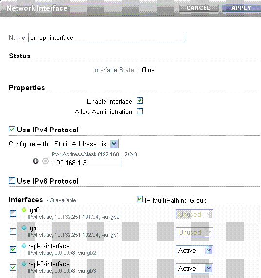
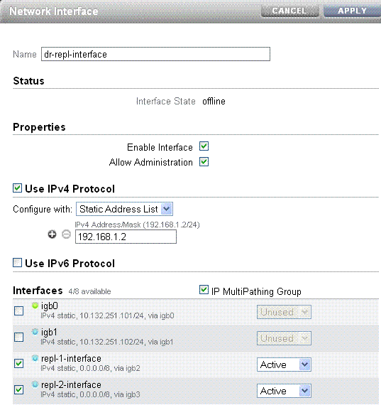
The bonded interface is a new interface, such as dr-repl-interface, with igb2 and igb3 configured as an IPMP group. For example, the network settings of the dr-repl-interface is shown in Figure 8-4.
Figure 8-4 igb2 and igb3 in an IPMP Group
Description of "Figure 8-4 igb2 and igb3 in an IPMP Group"
Note:
The interface names and IP addresses shown on the screens in this chapter are examples only. You must verify the interface names in your environment and use them accordingly.
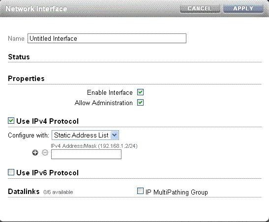
In the Properties section, if you select the Allow Administration option, management is enabled on the interface. To create an IPMP Group with two interfaces, such as igb2 and igb3, you must click the + icon (next to Interfaces) on the Figure 8-2. The Network Interface screen is displayed, as shown in Figure 8-5.
Figure 8-5 Creating a New IPMP Group Interface
Description of "Figure 8-5 Creating a New IPMP Group Interface"
Enter a name for the new interface. In the Properties section, select the Enable Interface option. Select the IP MultiPathing Group option to configure two interfaces, such as igb2 and igb3, in an IPMP group.
8.4.4.2 Configure Option 2: ASR Support and Shared Path for Management and Disaster Recovery, with Single Management URL
In this custom configuration, the igb0 port on your active storage head (head 1) is used, and the management option is enabled. The igb0 port on your stand-by storage head (head 2) is not used. The igb1 port on your stand-by storage head (head 2) is used, and the management option is disabled. The igb2 and igb3 ports are bonded with IP Multipathing (IPMP), and the management option is enabled on both igb2 and igb3.
This configuration option offers the following benefits:
-
Supports Automated Service Request (ASR) for the storage appliance included in the Exalogic machine, using ports
igb0andigb1 -
Supports disaster recovery for the Exalogic machine, using ports
igb2andigb3 -
Provides Exalogic Configuration Utility, which is used to reconfigure the Exalogic machine based on your specific requirements, with ports
igb0andigb1 -
Provides single management URL for both storage heads, using ports
igb2andigb3
Note:
This option does not separate the management path from the disaster recovery path.
To configure this option, complete the following steps:
8.4.4.3 Configure Option 3: ASR Support and No Disaster Recovery, But with Single Management URL
In this custom configuration, the igb0 port on your active storage head (head 1) is used, and the management option is enabled. The igb0 port on your stand-by storage head (head 2) is not used. The igb1 port on your stand-by storage head (head 2) is used, and the management option is disabled. The igb2 port uses a virtual IP, and the management option is enabled. The igb3 port is not used.
This configuration option offers the following benefits:
-
Supports Automated Service Request (ASR) for the storage appliance included in the Exalogic machine, using ports
igb0andigb1 -
Provides Exalogic Configuration Utility, which is used to reconfigure the Exalogic machine based on your specific requirements, with ports
igb0andigb1 -
Provides single management URL for both storage heads, using the port
igb2
Note:
This option does not offer disaster recovery support. When you use this configuration option, you may connect the free hanging cable from igb3 to the Cisco Management switch.
To configure this option, complete the following steps:
8.4.5 Default Storage Configuration
By default, a single storage pool is configured. Active-passive clustering for the server heads is configured. Data is mirrored, which yields a highly reliable and high-performing system.
The default storage configuration is done at the time of manufacturing, and it includes the following shares:
-
Two exclusive NFS shares for each of the Exalogic compute nodes - one for crash dumps, and another for general purposes
In this scenario, you can implement access control for these shares, based on your requirements.
-
Two common NFS shares to be accessed by all compute nodes - one for patches, and another for general purposes
Table 8-1 Default Configuration of the storage appliance
| Default Configuration | Name |
|---|---|
|
Storage pool |
|
|
Projects |
|
|
Shares |
|
Note:
This table represents the default configuration of the storage appliance before the Exalogic machine rack configuration is modified at the customer's site. Oracle Exalogic Configuration Utility does not alter this configuration.
8.4.6 Custom Configuration
You can create and configure a number of projects and shares on the storage appliance to meet your specific storage requirements in the enterprise.
You can implement custom configuration, such as the following:
-
Custom projects, such as
Dept_1,Dept_2. -
Custom shares, such as
jmslogs,jtalogs. -
Creation and administration of users.
-
Access control for custom shares.
Note:
For information about the recommended directory structure and shares, see the Oracle Fusion Middleware Exalogic Enterprise Deployment Guide.
