2 Reference Topology and Slicing Diagram
This chapter describes Exalogic enterprise deployment reference topologies. The instructions and diagrams in this guide describe two scenarios, to which variations may be applied. The chapter also includes the horizontal slicing diagram for an example Exalogic machine configuration.
It contains the following sections:
-
Scenario1: Exalogic Machine Connected to Oracle Database or RAC over 10 Gb Ethernet
-
Scenario2: Exalogic Machine Connected to Oracle Exadata Database Machine via InfiniBand
-
Example: Horizontal Slicing Within Exalogic Machine Quarter Rack
2.1 Scenario1: Exalogic Machine Connected to Oracle Database or RAC over 10 Gb Ethernet
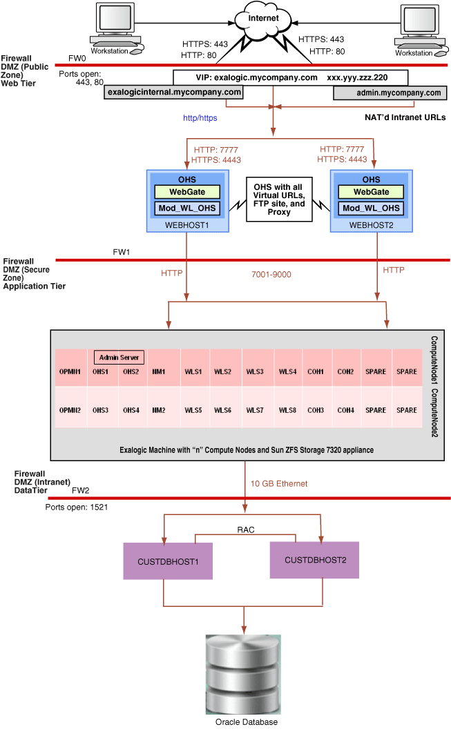
Figure 2-1 illustrates how an Exalogic machine is connected to an Oracle database or RAC over 10 Gb Ethernet in the enterprise deployment reference topology.
Figure 2-1 Exalogic Enterprise Deployment Reference Topology with Oracle Database over Ethernet in the Data Tier

Description of "Figure 2-1 Exalogic Enterprise Deployment Reference Topology with Oracle Database over Ethernet in the Data Tier"
You can use the procedures described in this guide to configure this reference topology. In addition, you must create two vNICs (vnic0/vnic1) for connecting an Oracle Exalogic machine to Oracle database or RAC over a 10 GB Ethernet link. For information about creating these vNICs, see Section 3.5.2, "Connecting to Oracle Database Over Ethernet".
Note:
Although the figure shows 7001-9000 ports, ensure that only ports that are used will be opened.
2.2 Scenario2: Exalogic Machine Connected to Oracle Exadata Database Machine via InfiniBand
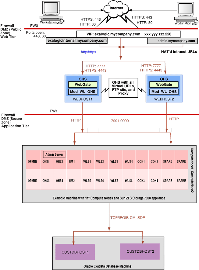
Figure 2-2 illustrates how an Exalogic machine is connected to an Oracle Exadata Database Machine together on the same InfiniBand fabric.
Figure 2-2 Exalogic Enterprise Deployment Reference Topology with Oracle Exadata Database Machine

Description of "Figure 2-2 Exalogic Enterprise Deployment Reference Topology with Oracle Exadata Database Machine"
You can use the procedures described in this guide to configure this reference topology. For information about connecting an Oracle Exalogic machine to Oracle Exadata Database Machine, see the Oracle Fusion Middleware Exalogic Machine Multirack Cabling Guide.
Note:
Although the figure shows 7001-9000 ports, ensure that only ports that are used will be opened.
2.3 Processor Cores for Exalogic X86 Machines
The number of processor cores on an Exalogic compute node depends on the machine version. For example, a compute node on a standard Exalogic X2-2 machine has two 6-core processors (12 cores in total), and a compute node on a standard X3-2 machine has two 8-core processors (16 cores in total).
Although the reference topologies show two compute nodes, the number of compute nodes available for your application deployment and configuration depends on your Exalogic machine configuration. However, you can extrapolate and use the example scenario described in this guide to set up an enterprise reference topology based on your specific requirements.
2.4 Introduction to Tiers
This section introduces the following tiers:
2.4.1 Web Tier
Nodes in the web tier are located in the DMZ public zone.
The configuration example described in this guide uses Oracle HTTP Server as the web server.
In this tier, two nodes WEBHOST1 and WEBHOST2 run Oracle HTTP Server configured with mod_wl_ohs.
Through mod_wl_ohs, which allows requests to be proxied from Oracle HTTP Server to WebLogic Server, Oracle HTTP Server forwards the requests to WebLogic Server running in the application tier.
The web tier also includes an external load balancer router to handle external requests. External requests are sent to the virtual host names configured on the load balancer. The load balancer then forwards the requests to Oracle HTTP Server.
On the firewall protecting the web tier, only the HTTP ports are open: 443 for HTTPS and 80 for HTTP.
Note:
A separate installation of Oracle HTTP Server inside the Exalogic machine in the application tier provides internal load balancing and routes requests via IP over InfiniBand (IPoIB) and Ethernet over InfiniBand (EoIB). This installation is optional.
2.4.1.1 Parameters for Web Server Plug-Ins
You enter the parameters for each Web server plug-in special configuration files. Each Web server has a different name for this configuration file and different rules for formatting the file. In this guide, you must set the Oracle WebLogic cluster parameter to specify the floating IP addresses of Oracle WebLogic Managed Server and their ports in the configuration file used by the plug-in for Oracle HTTP Server.
For more information, see the Oracle Fusion Middleware Using Web Server 1.1 Plug-Ins with Oracle WebLogic Server. In addition, see Chapter 6, "Configuring Oracle HTTP Server".
2.4.2 Application Tier
Nodes in the application tier are located in the DMZ secure zone.
In this tier, Oracle WebLogic Server is configured with Managed Servers for running Oracle Fusion Middleware components on compute nodes in Oracle Exalogic machine. The number of compute nodes in Oracle Exalogic machine depends on your purchased hardware configuration, such as Oracle Exalogic machine full rack (30 compute nodes), Oracle Exalogic machine half rack (16 compute nodes), and Oracle Exalogic Machine quarter rack (8 compute nodes).
Optionally, you can configure and run Oracle HTTP Server instances on your Exalogic compute nodes if you wish to load balance traffic between WebLogic server instances running on the compute nodes. Additionally, Oracle HTTP Server instances running on Exalogic compute nodes provide routing of requests from Oracle HTTP Server to WebLogic server instances via IPoIB and EoIB.
Note:
The topology diagrams show only two Oracle Exalogic compute nodes (ComputeNode1 and ComputeNode2) in the application tier. The configuration procedures described in this guide are based on horizontal slicing (aaaaaaa) within a single Oracle Exalogic machine. In addition, it considers a simple configuration scenario, including two clusters of 8 Managed Servers each on ComputeNode1 and ComputeNode2, Node Manager running on both of the compute nodes, and the Administration Server running on ComputeNode1. For the Administration Server running on ComputeNode1, the second compute node ComputeNode2 is used as the back-up machine.
You can use this example configuration to identify and implement your specific configuration requirements.
2.4.3 Data Tier
Nodes in the data tier are located in the most secured network zone (the intranet).
In the data tier, you should consider the following configuration scenarios:
-
Oracle Exalogic machine connected to Oracle database or RAC over 10 Gb Ethernet
-
Oracle Exalogic machine connected to Oracle Exadata Database Machine over InfiniBand
If you are connecting your Oracle Exalogic machine to an Oracle database or RAC over Ethernet, you must create vNICS and VLANs, as necessary. For more information, see Section 3.5.2, "Connecting to Oracle Database Over Ethernet".
If you are connecting your Oracle Exalogic machine to Oracle Exadata Database Machine to communicate via InfiniBand, you must connect the Oracle Exalogic machine to Oracle Exadata Database Machine, as described in the Oracle Fusion Middleware Exalogic Machine Owner's Guide.
On the firewall protecting the data tier, the database listener port (typically, 1521) is required to be open. The LDAP ports (typically, 389 and 636) are also required to be open for the traffic accessing the LDAP storage in the Exalogic enterprise deployment.
2.5 Load Balancer Requirements
This enterprise topology uses an external load balancer. This external load balancer should have the following features:
-
Ability to load-balance traffic to a pool of physical servers through a virtual host name: Clients access services using the virtual host name (instead of using actual host names). The load balancer can then load balance requests to the servers in the pool.
-
Port translation configuration should be possible, so that incoming requests on the virtual host name and port are directed to a different port on the backend servers.
-
Monitoring of ports on the servers in the pool to determine availability of a service.
-
Virtual servers and port configuration: Ability to configure virtual server names and ports on your external load balancer, and the virtual server names and ports must meet the following requirements:
-
The load balancer should allow configuration of multiple virtual servers. For each virtual server, the load balancer should allow configuration of traffic management on more than one port. For example, for Oracle HTTP Server in the web tier, the load balancer needs to be configured with a virtual server and ports for HTTP and HTTPS traffic.
-
The virtual server names must be associated with IP addresses and be part of your DNS. Clients must be able to access the external load balancer through the virtual server names.
-
-
Ability to detect node failures and immediately stop routing traffic to the failed node.
-
Fault-tolerant mode: It is highly recommended that you configure the load balancer to be in fault-tolerant mode.
-
It is recommended that you configure the load balancer virtual server to return immediately to the calling client when the backend services to which it forwards traffic are unavailable. This is preferred over the client disconnecting on its own after a timeout based on the TCP/IP settings on the client machine.
-
Sticky routing capability: Ability to maintain sticky connections to components. Examples of this include cookie-based persistence, IP-based persistence, and so on.
-
The load balancer should be able to terminate SSL requests at the load balancer and forward traffic to the backend real servers using the equivalent non-SSL protocol (for example, HTTPS to HTTP).
Note:
These are recommendations only. You can use your existing data center practices in the Oracle Exalogic environment.
2.6 Example: Horizontal Slicing Within Exalogic Machine Quarter Rack
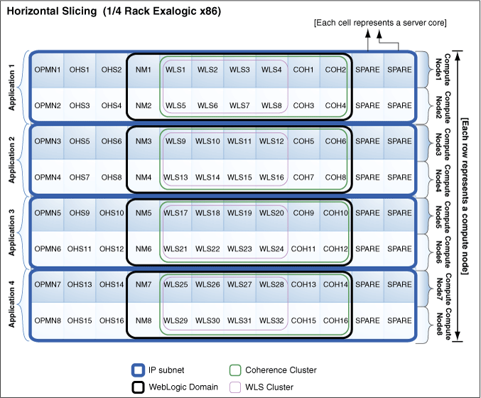
Figure 2-3 illustrates horizontal slicing of an Oracle Exalogic machine quarter rack for Oracle Solaris and Oracle Linux physical environments.
Figure 2-3 Horizontal Slicing Within Exalogic Machine Quarter Rack

Description of "Figure 2-3 Horizontal Slicing Within Exalogic Machine Quarter Rack"
Based on this example, you can configure the following to deploy an application, such as Dept_1:
-
A dedicated Node Manager instance per compute node
-
A dedicated Oracle Process Manager and Notification Server (OPMN) process on each compute node
-
Optional: two Oracle HTTP Server instances on each compute node if you wish to use Oracle HTTP Server inside Exalogic to load balance traffic on the IPoIB network
-
Two storage-enabled Coherence Servers per compute node
-
One WebLogic cluster with 8 Managed Servers across two compute nodes
-
One Coherence cluster across two compute nodes
Note:
The horizontal slicing of an Exalogic machine is an example only. All of the above are in the same IP subnet.