Connectivity
This chapter covers the following topics:
- Introduction to Connectivity
- Connectors and Target Models
- Connectors and Configuration Rules
- Connectors and the Runtime User Interface
Introduction to Connectivity
Some Models require end users to indicate how certain components are related to one another and then enforce specific constraints when the two objects are connected. This type of runtime behavior can be implemented in Configurator Developer by creating Connectors. You create a Connector to define a relationship between a Model (or a Component) and another Model. Then, you build rules in which these nodes are participants to ensure all connections are valid at runtime.
For example, one kind of Model that requires connectivity enables an Oracle Configurator end user to define a network. A network is a system comprised of interrelated or interconnected elements, such as telephones, computers, or television stations. Each kind of network is unique, but all networks are comprised of individual components, that are somehow related (or connected) to one another. For details, see the example Telephone Network Model.
Also consider a Model in which end users must configure a computer server system. In this Model, an end user must indicate on which rack shelf each server component will be installed. To implement this in Configurator Developer, you define a Connector on each server component and specify the rack Model as its target. You then build rules to ensure that all connections made at runtime are valid (for example, each component will fit on the specified shelf in the rack).
Other Models may require you to create Connectors to specify physical connections between components, such as to indicate how an item must ultimately be assembled. However, it is important to remember that Connectors can be used to define almost any type of relationship between components, and the rules you define will ensure that only valid relationships are created at runtime. For this reason, Connectors are a very flexible and powerful modeling tool.
Note: The Generic Configurator UI does not support connectivity. In other words, an Oracle Configurator end user can connect components only in User Interfaces that you create in Configurator Developer. For more information about the Generic Configurator UI, see the Oracle Configurator Implementation Guide.
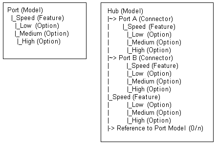
In a runtime Oracle Configurator, an end user configures a telephone network by defining circuits. The user creates a circuit by connecting two Ports, which are part of a configurable Hub Model. One or more configurable Ports exist per circuit, and each Port includes the parameter Speed. The Speed parameter includes the Options High, Medium, and Low, and any two connected Ports must have the same speed. The end user connects two Ports at a time, while constraints defined in Configurator Developer ensure that the Speed of the connected Ports is the same. When all required selections and connections are made and the configuration is valid, the data is passed back to the host application for downstream processing.
The Models required to create the network and rules described in this example are shown in Telephone Network Models.

Note: Connectivity was designed for users who need to update a large network of connected components, such as a long-distance telephone network. Models that support connectivity, and Models that support reconfiguration of an installed configuration, are implemented primarily by businesses in the Telecommunications Service Ordering industry. For additional information about this functionality, see the Oracle Telecommunications Service Ordering Process Guide.
Connectors and Target Models
In Configurator Developer, you can create a Connector on a BOM Model or a Component node. (In the Model structure, the Connector itself actually appears beneath the node on which it was created). However, a Connector’s target is always a Model. In other words, an Oracle Configurator end user can create a connection from:
-
A BOM Model to another Model
-
A Component to a Model
The target Model can be any Model in the CZ schema (in other words, any Model that appears in the Main area of the Repository). A Model may have one or multiple Connectors, and you can specify whether a connection is required to create a valid configuration.
In Configurator Developer, the Model that is the target of a Connector must be referenced from the Model being configured at runtime. This is because an instance of the target Model must exist in the configuration before an end user can connect the Connector’s parent and the target Model (and the only way a Model can be part of another Model’s structure when it is a Reference).
Before an Oracle Configurator end user can connect two components at runtime, an instance of each component must exist in the configuration. This is an important consideration when building your Model in Configurator Developer, because all components that you want an end user to be able to connect at runtime must be part of the Model’s structure.
If an instance of the target Model does not exist at runtime, the runtime Oracle Configurator displays an empty list of targets when an end user attempts to create a connection. See Connectors and the Runtime User Interface.
Target Model Structure and Rules
When you create a Connector and specify a target Model in Configurator Developer, the read-only structure of the target Model is visible beneath the Connector node and you can use nodes from the target Model when defining configuration rules for the Model in which the Connector is defined. The target Model’s read-only rules are also visible when you are working in the Configuration Rules module. To modify the structure of a target Model or any of its rules, you must open the target Model for editing in the Workbench.
Although the target Model and its structure are visible beneath the Connector node in Configurator Developer, a new instance of the target Model is not automatically created when another instance of the Connector’s parent is added at runtime. If the configuration requires another instance of the target Model, the end user must add it (see Creating Instances at Runtime). For more information about instantiation, see Introduction to Instantiation .
Connectors and Configuration Rules
A unique characteristic of Models that contain Connectors is that you can define configuration rules relating instances that may be connected at runtime. However, these rules do not propagate until the end user actually connects the components that are participants in the rule. Then, the rule verifies that the connection is valid and propagates to other parts of the Model (depending on the rule’s definition). If the connection is valid, the Oracle Configurator end user can continue; otherwise, a contradiction message explains why the connection is invalid. For an example of this behavior, see Runtime Behavior of Rules Relating Connected Components.
Before you can create rules to relate components that may be connected at runtime, you must create Connector nodes in Configurator Developer and specify the Model that serves as the Connector’s target. (See Creating a Connector.) You can then use any nodes within the structure of the Connector’s target Model to define any type of configuration rule.
Connector nodes themselves cannot participate in configuration rules, but you can use a Connector node when defining a Configurator Extension Rule. See Connection Filter Configurator Extension.
The ability to use nodes within the structure of a Connector’s target enables you to create configuration rules between optional instantiable components, which are Model or Component nodes that may exist at runtime, but are not required to create a valid configuration (for example, a Component or Model Reference that has an Initial Minimum of 0). For more information, see Rules that Relate Components and Models.
Note: Use caution when using nodes within a target Model as participants in the parent Model’s configuration rules. If a node in the target Model is modified or deleted, the rule in the parent Model may become invalid. In this case, Configurator Developer displays an error message when you generate logic for the parent.
Note: It must be possible for Oracle Configurator end users to connect all necessary components in a configuration in the absence of any previous end user requests or default option selections. For details, and an important Model design suggestion, see the Oracle Configurator Modeling Guide.
Second-Level Connectors
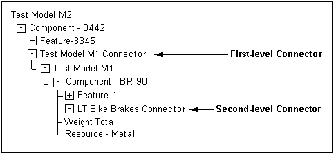
A target Model can also contain a Connector. When this occurs the structure of the second-level (nested) Connector’s target Model is not visible in Configurator Developer. Because the second-level Connector’s target Model is not visible, nodes from that Model cannot participate in the parent Model’s configuration rules.
First and Second-Level Connectors shows how a Model containing both first and second-level Connectors appears in Configurator Developer.
First and Second-Level Connectors

To work around the restriction of creating rules using nodes from a second-level Connector’s target Model, perform the following:
-
Create an intermediate node in the first-level target Model. (Feature 1 in Connectors and Target Models.)
-
Define a rule in the first-level target that includes the intermediate node and the node(s) you want to use in the nested Connector’s target.
-
Define a rule in the root Model using the intermediate node to produce the desired results.
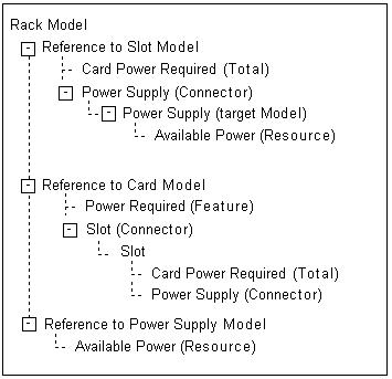
Example: The Rack Model shown in Rack Model Structure contains References to three Models: Slot, Card, and Power Supply.

In the Rack Model, Card has a Connector to Slot, which in turn has a Connector to Power Supply. You need to define a rule that states Power Required consumes from the Available Power Resource in Power Supply. In the Rack Model, however, Power Supply is the target of a second-level Connector (in Card), so you cannot use a node from Power Supply to create the rule.
To work around this restriction, define an intermediate node in Slot (in this example, the Card Power Required Total) to reflect information from Card, and then define the rule in two pieces.
First, relate the Power Required Total in Card to the desired node in Power Supply:
Card.Power Required Consumes from Power Supply.AvailablePower
Then, create a rule in Slot relating Power Required with the intermediate node:
Power Required Contributes to Slot.Card Power Required
Runtime Behavior of Rules Relating Connected Components
If a rule contains one or more nodes from one or more Connector’s target Models, the rule does not propagate until the Connector is connected at runtime.
For example, you want to contribute a constant value to a Total when either Option1 from Component A or Option2 from target Model B is added to the configuration at runtime. You define a "Contributes To" relation (Numeric Rule) and include Option1 and Option2 as participants. This rule will not contribute to the Total, even if Option1 and Option2 are selected, until the end user connects an instance of Component A and an instance of Model B.
Connection Filter Configurator Extension
You may want to control which instances of the target Model appear for selection when an Oracle Configurator user wants to create a connection. To do this, define a Connection Filter Configurator Extension and assign it to the Connector node whose target instances you want to filter.
For example, you want to prevent end users from creating more than one connection to an instance of Model X. You can define a Configurator Extension that makes Model X unavailable once the end user creates a connection to it. Then, assign the Connector that has an instance of Model X as its target to the Configurator Extension in Configurator Developer.
To assign a Configurator Extension to a Connector, the Connector must be defined in the Model that is open for editing (that is, not in the Connector’s target Model). For example, you are editing Model A, which has a Connector to Model B. Model B also contains a Connector that is visible in the Structure area of the Workbench. In this example, you cannot assign a Configurator Extension to the Connector in Model B when editing Model A.
For more information about creating Configurator Extensions, see the Oracle Configurator Extensions and Interface Object Developer’s Guide.
For more information about creating connections at runtime, see Connectors and the Runtime User Interface.
Connectors and the Runtime User Interface
When you generate a User Interface, Configurator Developer uses the UI Master Template you select to create UI controls for each Connector in your Model. For details, see:
At runtime, when the end user activates a UI control to create a connection, a secondary window displays each available instance of the Connector’s target Model. The end user then creates the connection by selecting a specific instance of that Model.
At least one instance of a Model that is the target of a Connector must exist in the configuration before an Oracle Configurator user can connect a component to it.
For example, the minimum number of instances defined for a reference to Model B is 0 (zero). Model B is the target of a Connector that is defined in Model A. When the configuration session begins, the end user cannot connect an instance of Model A to an instance of Model B because no instances of Model B exist. Therefore, until Model B is instantiated, no targets are available when the end user clicks the "Create Connection" button in Model A’s UI Page.
Connections and Runtime Navigation
When an end user connects two components at runtime, the name of the Model that is the target of the connection appears as a hypertext link next to the "Create Connection" button. Clicking this link navigates to the connected Model’s UI Page.
A Connection Navigator control displays a list of components that are connected to a selected component at runtime. Each component appears as a link the end user can click to navigate to that component.
Connecting Hidden Components
A component might not appear in the UI due to a display condition that you define in Configurator Developer, or because the structure node’s Include in Generated UI setting is not selected in Configurator Developer. In either case, the component is not visible and an end user cannot navigate to it. However, unlike components and options that are not available because of their effectivity, hidden components do exist in the configuration. Therefore, an end user can create a connection, even when the target component does not appear in the UI.
For more information about defining display conditions, see Defining a Condition for Runtime Display and Behavior.