 Part 1: Creating a Logical UML Class Model

Before transforming the logical model, you create a specific project for your physical model, then you focus on some properties that might be interesting to observe on how the transformer behaves. From a database designer point of view, you should notice that in the class model, some names contain spaces, some class have no primary keys defined. Some have a generalization class, and there are many to many association and names defined on both side of associations. To create the first cut database diagram, perform the following steps:
-
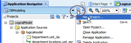
Click the Application icon and select New Project from the context menu to open the New Gallery. (alternatively, select File | New from the main menu. )
-
In the New Gallery select the Database Project option.
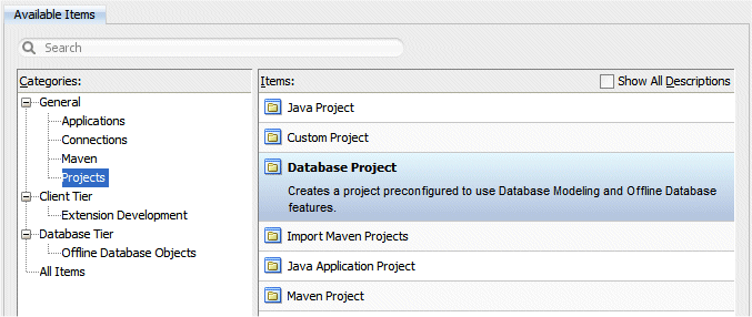
Click OK.
-
In the Create Database Project dialog, type PhysicalModel as the Project name

Click Finish.
-
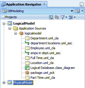
The Application Navigator should look like the following:
-
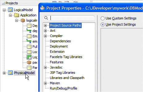
Double click the PhysicalModel node to open the project properties dialog.
-
In the Project Properties dialog, select the Dependencies node in the left pane and click the Edit button
 .
. 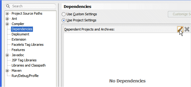 Creating dependencies between projects.
 Read more...
Complex applications generally comprise multiple projects, which may be related though dependencies. That is, project A (Physical model) must depend on project B (Logical model) when project A uses classes or resources from project B. When this dependency is set, compiling project A will automatically compile project B.
-
In the Edit Properties dialog, expand the LogicalModel node and check the Build Output checkbox.
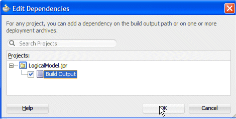
Click OK. Click OK again.
-
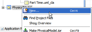
Right-click the PhysicalModel node and select New from context.
-
In the New Gallery, select the Database Tier | Offline Database Objects and select Offline Database.
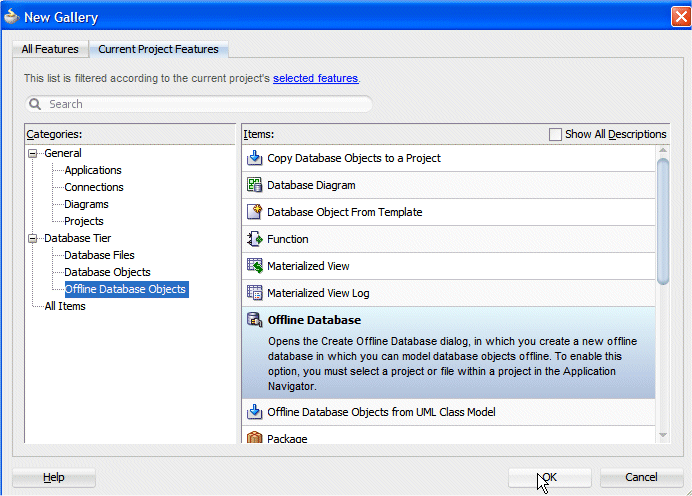
Click OK.
-
In the Create Offline Database dialog type basic as the name.
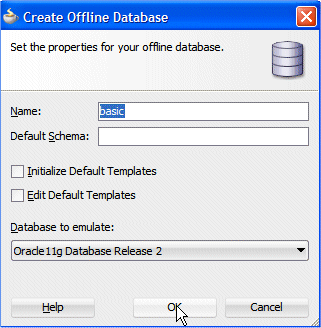
Click OK.
-
Click the Save All button
 to save your work.
 -
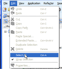
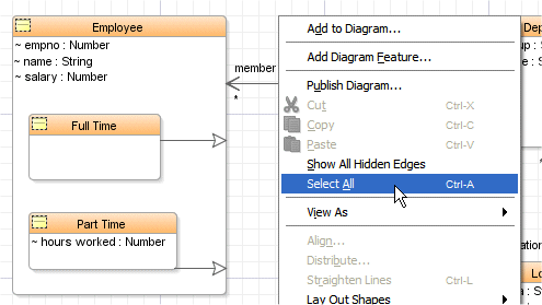
Having the LogicalDatabase class diagram selected, select Edit --> Select All from the main menu to select all classes in the diagram.
-
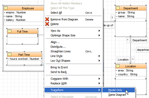
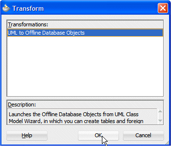
Right-click within any class and select Transform --> Model Only from the context menu.

-
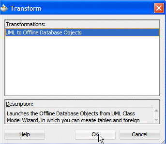
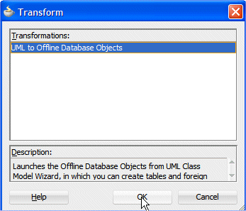
In the Transform dialog, select UML to Offline Database Objects. If we had opened JDeveloper with another role, than the Database Edition role, we would have other options to choose from.

Click OK.
Offline database is a technology in JDeveloper that allows you to create and edit database object definitions within a project.Read more...
Definitions are saved as .xml files, using the same editors that are used to create and edit database objects on live database connections.
You can create new offline database objects, or import them from a connection to a live database. After you have finished working with them, you can generate DDL that can be used to create and update database definitions in online database schemas.
-
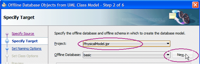
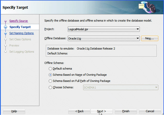
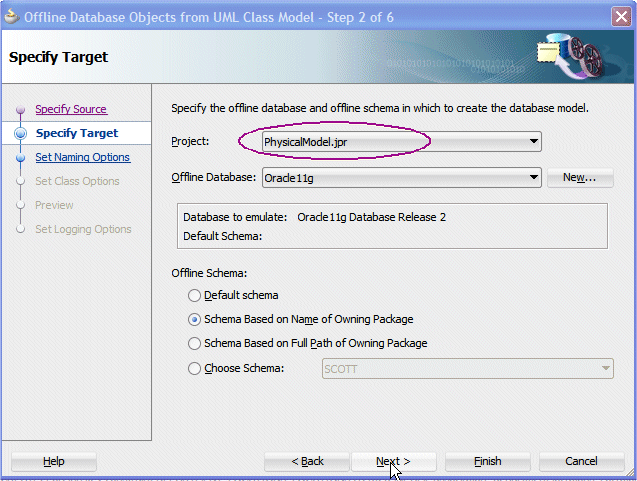
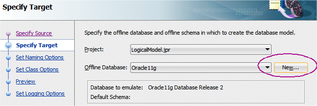
In the Offline Database Objects from UML Class Model dialog, select the PhysicalModel project from the list, and select the Schema Based on the Name of Owning Package option.
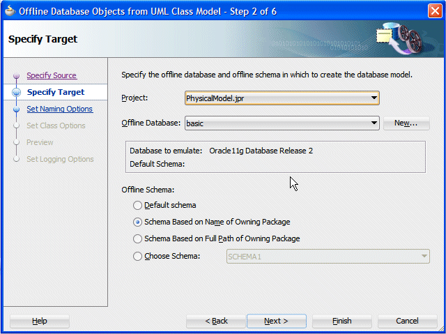
Click Next.
Notice that the default Offline Database is the one that you created just before.Read more...
By default the Database to Emulate is set to Oracle11g Database Release 2. You can specify the type of database that the offline database emulates, thereby determining the kinds of offline database object and the data types that will be supported in the offline database.
-
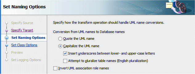
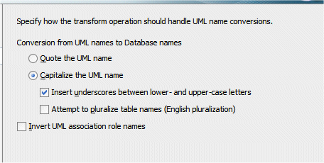
In the Set Naming Options step, check the following options:
- Capitalize the UML name
- Insert underscores between lower and uppercase letters
- Attempt to pluralize table names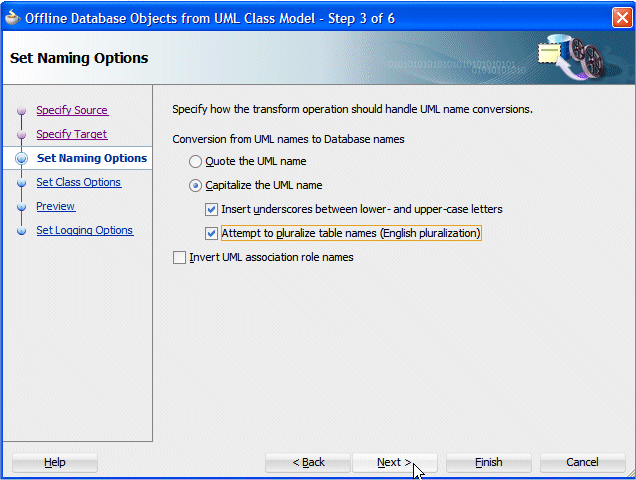
Click Next
-
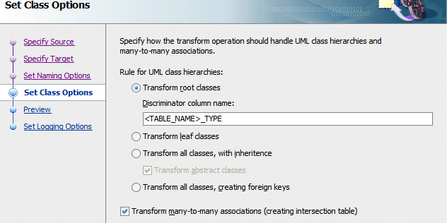
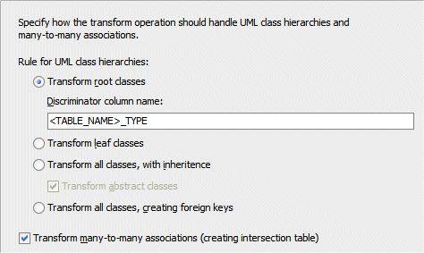
Select the Transform root classes option, and check Transform many-to-many associations.
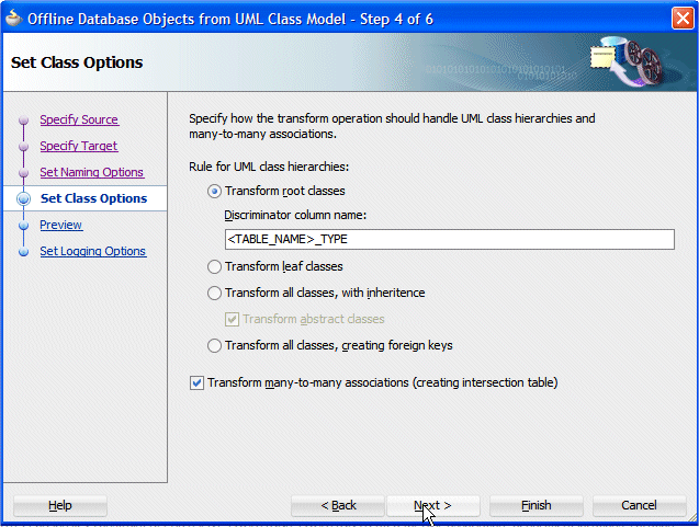
Click Next.
-
Expand all components that the wizard is prepared to create. See that column EMPLOYEE_TYPE is added as a discriminator column for handling Part Time and Full Time employee subtypes.
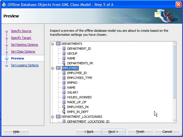
Click Next then Finish.
-
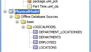
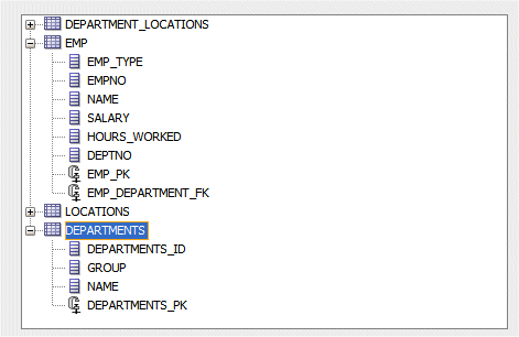
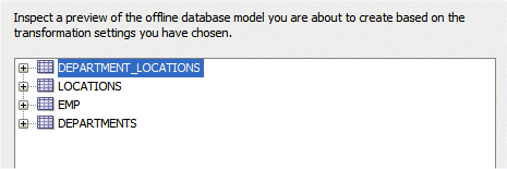
The transformed objects now appear in the Application Navigator. Notice the name generated for the intersection table (Department_Locationses).
-
Double-click the Department_Locationses node to edit the table properties.
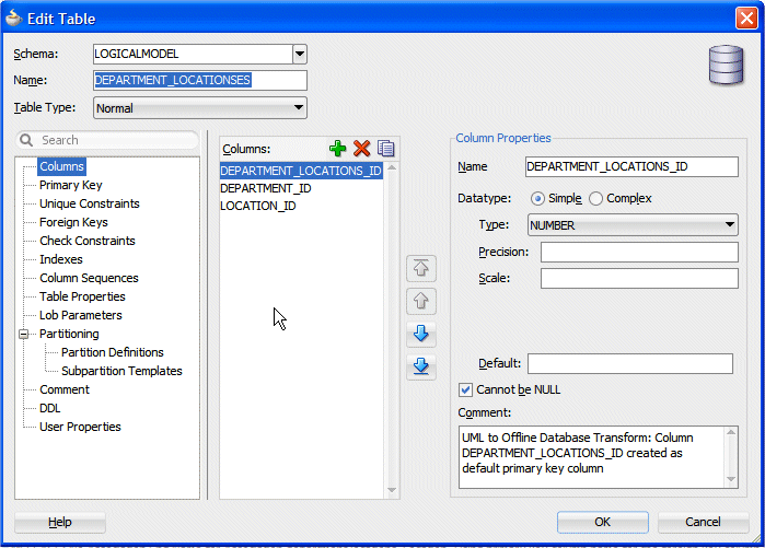
Explore the various properties of this table: attributes, primary key and foreign keys. Notice that the intersection table has a primary key based on a created column (DEPARTMENT_LOCATIONS_ID) and has also 2 foreign keys one for department_id and the other for location_id.
Click OK. -
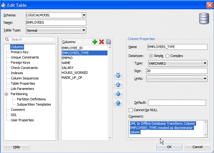
In the Application Navigator, double-click the Employees table to edit it. Notice the comment created for the Employees_type column indicating that this column is the discriminator column for making distinction between Full Time and Part Time employees.
-
Explore the various other properties created for this table.
-
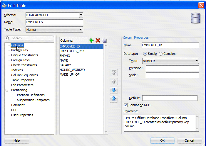
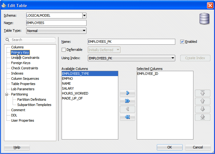
Notice that a Primary Key column EMPLOYEE_ID has been created.
-
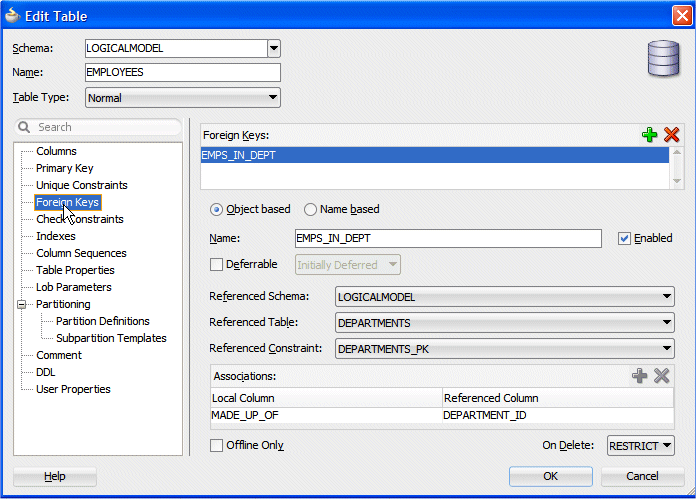
Examine the foreign key names and how they are made.
Click OK.
-
Click the Save All button
to save your work.
The way the transformer behaves may not fully satisfy your expectations and needs. You want to have more control on the rules that apply to the transformation of classes into tables. For example, you want the Employee table to be named Emp, the column empno to be used as the primary key, the Foreign Key columns to be named using the association name, and the intersection tables to be named differently than this attempt of pluralization.
-
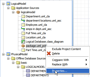
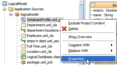
In the Application Navigator, right-click the package.uml_pck node and select Properties from context.
-
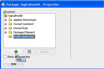
In the Package properties dialog, select the Profile Application node and click the Add button
 .
. 
-
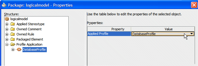
In the Properties pane, select DatabaseProfile from the list.
-
Select the Applied Stereotype node and click the Add button
. In the Properties pane, Type SCOTT as the name to give as the database name. 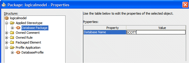
Click OK.
-
A new entry is now created in the Application Navigator named DatabaseProfile.uml_pa. Right-click and select Properties from dialog.
-
The properties dialog shows what database profile is going to be used from now on.
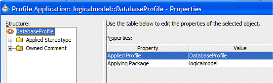
Click OK.
-
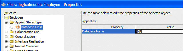
Right-click Employee.uml_cla and select Properties from context. In the Property dialog select Applied Stereotype and click the Add button
, then select Database Class from the list.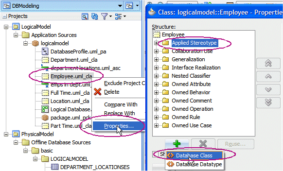
-
Enter EMP in the value field. This is the name you want to be generated as the table name for the employee class.
-
Expand the Owned Attribute | empno node and select Applied Stereotype, then click the Add button
. 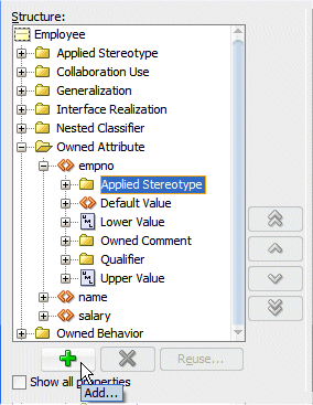
-
Enter the following property values:
Property Value Datatype NUMBER Datatype (Oracle) NUMBER(8,0) Datatype (SQL Lite) INT Is Primary Key? (checked) 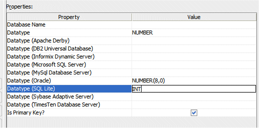 Notice all the different databases you can emulate.Read more...
Make sure that the properties you specify for a specific database are compatible with that database type. No validation controls is done at this point.
-
Repeat the operation for the name attribute, entering the following property values:
Property Value Datatype VARCHAR Datatype (DB2 Universal Database) VARCHAR(25) Datatype (Oracle) VARCHAR2(30) Datatype (SQL Lite) CHAR(20) 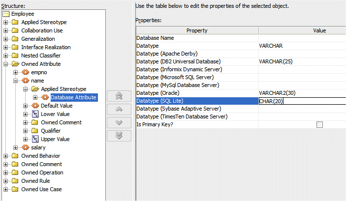
Repeat the operation for the salary attribute. Enter the following properties:
Property Value Datatype NUMBER(8,2) Datatype (Oracle) NUMBER(10,2) Datatype (SQL Lite) NUMBER(8,2) 
Click OK.
-
Right-click emps in dept.uml_cla in the Application Navigator and select Properties from context. In the Properties dialog, select Applied Stereotype and clicking the Add button
, select Database Association. 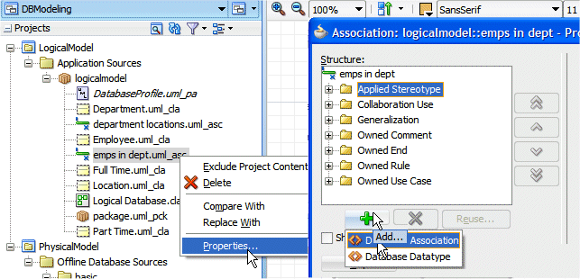
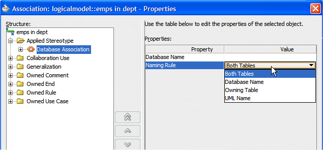
-
From the Naming Rule dropdown list, notice the rule that you can choose from and select Both Tables.
-
Expand the Owned End | made up of node, select Applied Stereotype and click the Add button
to add a new rule. 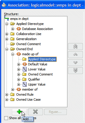
-
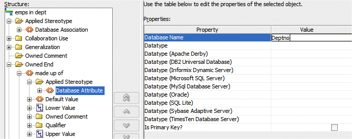
Type Deptno as the value for the database name field. It is the name you want to be used for the foreign key attribute.
Click OK.
-
Right-click department.uml_cla in the Application Navigator and select Properties from context. In the Class Properties dialog, select Applied Stereotype and clicking the Add button
, select Database Class. 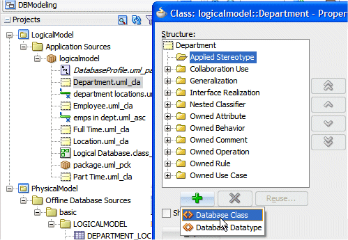
-
Type Departments as the Database name for this table.
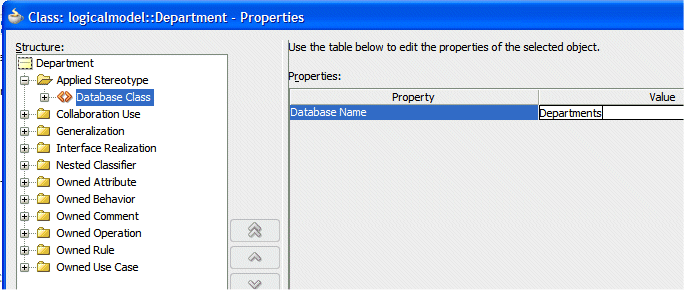
Click OK.
-
Right-click Location.uml_cla in the Application Navigator and select Properties from context. In the Class Properties dialog, select Applied Stereotype and clicking the Add button
, select Database Class. 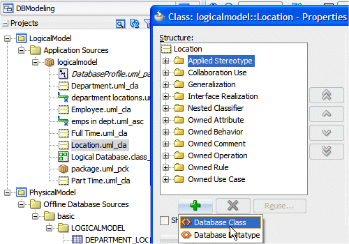
-
Type Locations as the name to give to the generated table.
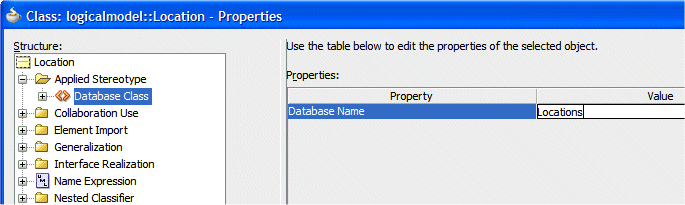
Click OK.
-
Right-click within the diagram and select Select All.
-
Right-click within the diagram and select Transform --> Model.
-
In the Transform dialog, Click OK to accept the default. (UML to offline Database Objects).
-
In step 2 of the wizard click the New button next to the Offline Database field.
-
In the Create Offline Database dialog, type Oracle11g as the Name and choose Oracle11g Database Release 2 as the database to emulate.
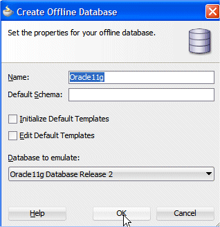
Click OK.
Oracle 11g Database Release 2 is the default database emulation in this version.
Read more...
It is recommended to clearly identify the database emulation you are using for the transformation process.
-
Back in the main dialog, click Next.
-
On the Set Naming options step, select Capitalize the UML name and check Insert underscores between lower- and upper -case letters.
Click Next.
-
In the Set Class Options step, choose the following options:
Click Next.
-
In the Preview step, notice the new names for tables and attributes.
Click Next then Finish.
-
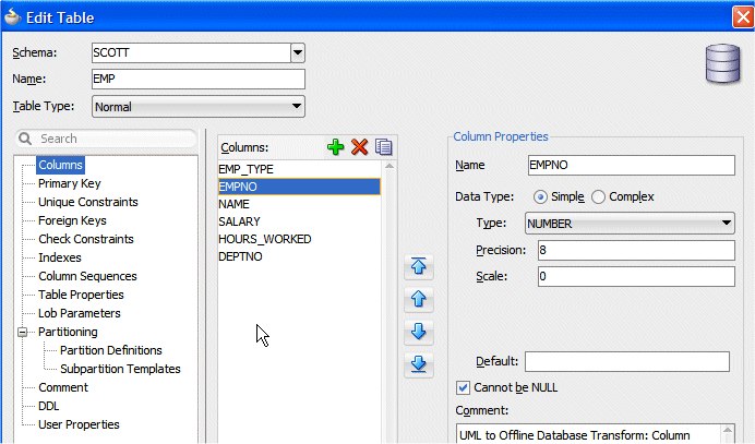
The Database node Oracle11g is created in the Application Navigator. Expand the nodes and double-click the EMP table name to open the Edit Table dialog.
-
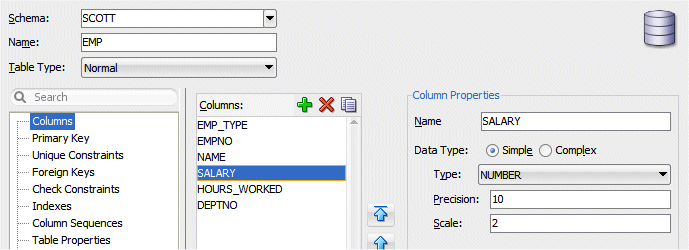
Review each column characteristics. Example for column Empno:
-
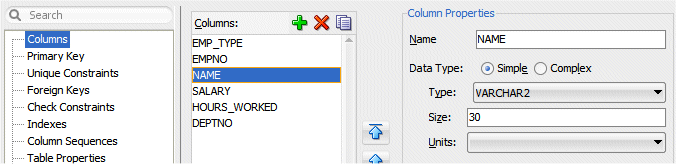
Example for column Name:
-
Example for column Salary:
-
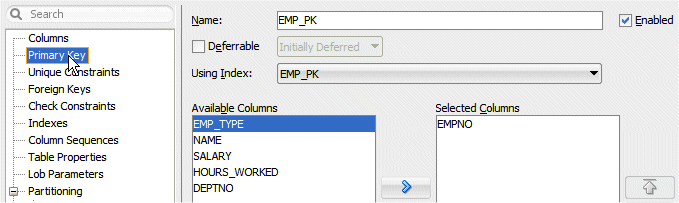
Review the Primary Key:
-
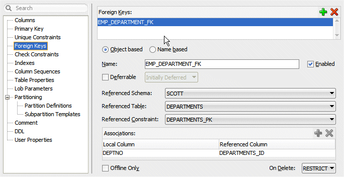
Review the Foreign key and notice the new names generated:
Click OK.
-
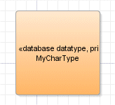
In the Component Palette, drag the Primitive Type icon
 onto the diagram. Rename it MyCharType.
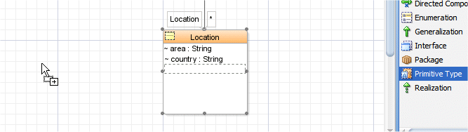
-
The new datatype appears on the diagram.
-
In the Application Navigator right-click MyChartType.uml_prt to open the Properties dialog. Select the Applied Stereotype node and click the Add button
.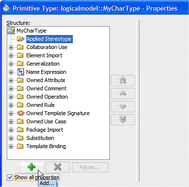
-
In the Properties pane, enter the following values:
Property Value Datatype VARCHAR(50) Datatype (DB2 Universal Database) CHAR(50) Datatype (Oracle) CHAR(50) Datatype (SQL Lite) VARCHAR2(50) 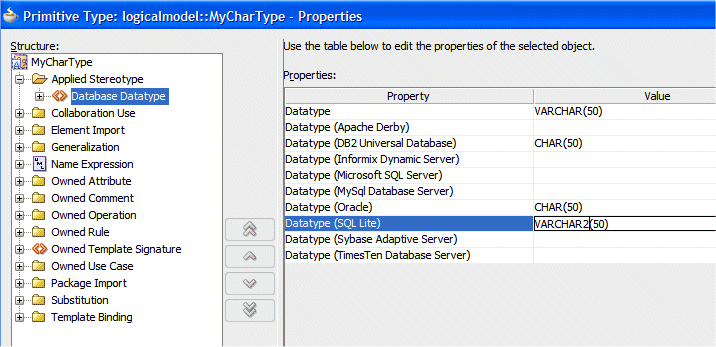
Click OK.
-
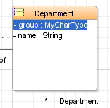
In the Department Class, using 'in place' edit, type MyCharType for the group attribute.
-
Double-click the Location class to open its properties. In the properties dialog, select the Owned Attribute | area node in the Structure pane and next to the Type field click the Select element button
 .
. 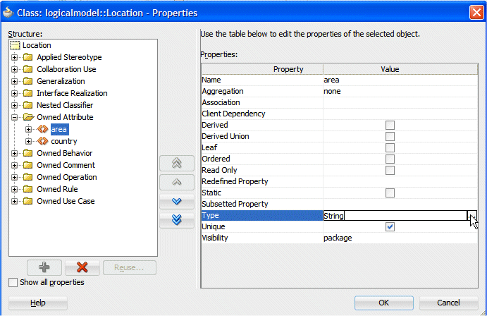
-
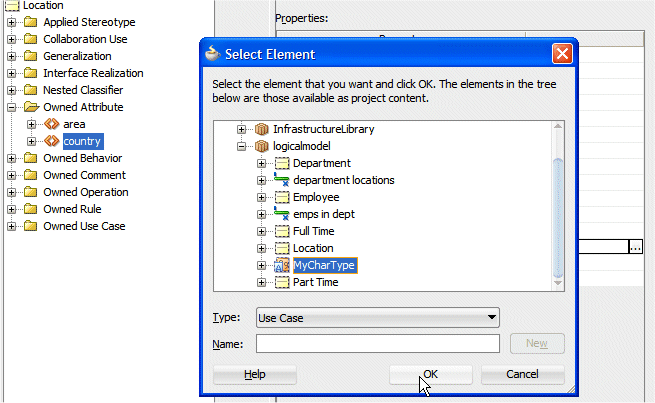
In the Select Element dialog, expand logicalmodel and select MyCharType.
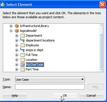
Click OK.
-
Repeat the operation for the country attribute.
Click OK then OK again.
-
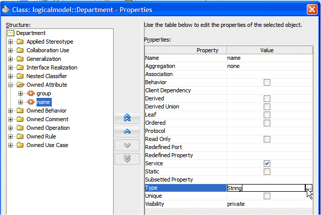
Back the the class diagram, double-click the Department class to open it. In the Properties dialog, select Owned Attribute | name and click the Select element button next to the Type.
-
In the Select Element dialog, select UML | Database Library | Primitive Types | DatabaseString30.
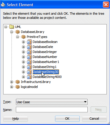
Click OK .
-
Click the Save All button
to save your work. -
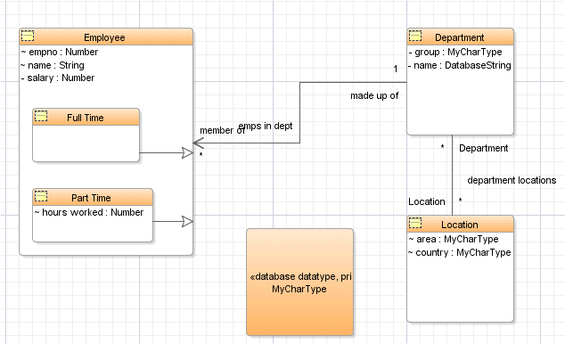
Your diagram should now look like the following:
-
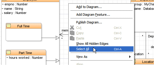
Right-click within the diagram and select Select All.
-
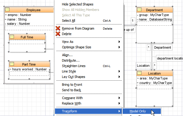
Right-click in one of the classes and select Transform --> Model only.
-
In the Transform dialog click OK.
-
In the Offline Database Objects from UML Class Model, select PhysicalModel for the Project.
Click Next.
-
In the Set Naming Option, check that the following options are selected:
Click Next.
-
In the Set Class Option, check that the following options are selected: .
Click Next.
-
In the Preview step, click Finish.
-
Repeat the operation to generate an Oracle Lite table structure: In the diagram, having the classes selected, right-click and select Transform --> Model Only.
In the Transform dialog, click OK.
-
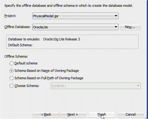
In the Offline Database Objects from UML Class Model dialog, in the Specify Target step, select the PhysicalModel project, then click the New button next to the Offline Database field.
-
In the Create Offline Database type OracleLite as the Name and select Oracle10g Lite Release 3 as the Database to emulate.
 d
d
Click OK.
-
Back in the Specify Target step, and since we want all the default options to be applied, click Finish.
-
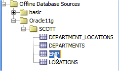
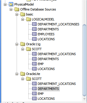
In the Application Navigator, you now have two offline database schemas defined. One for Scott in a Oracle Lite database and one for Scott in an Oracle 11g database.
-
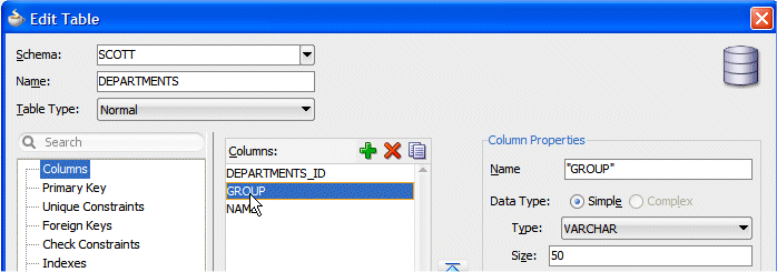
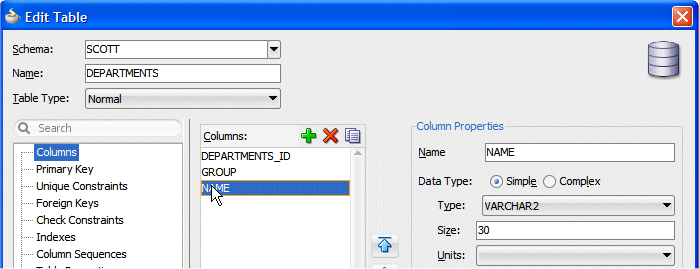
Double-click the Departments table in the OracleLite database and review the GROUP column characteristics. Notice the VARCHAR (50) type corresponding to your custom datatype for Oracle Lite databases.
-
Select the NAME column now and review its properties.
Click OK.
-
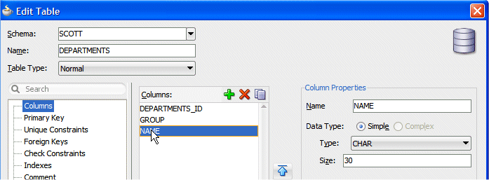
In the Application Navigator, double-click the Departments table in the Oracle11g database and review the GROUP column characteristics. Notice the CHAR (50) type corresponds to your custom datatype for Oracle 11g database.

-
Select the NAME column now and review its properties.
Click OK.
-
Click the Save All button
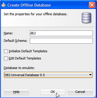
to save your work. Additionally, you could also experiment generating a database schema for a DB2 database and review the column properties.Read more...
In the diagram, having the classes selected, right-click and select Transform --> Model Only. In the Offline Database Objects from UML Class Model dialog, in the Specify Target step, select the PhysicalModel project, then click the New button next to the Offline Database field and create the DB2 database emulation.
Read more...
JDeveloper provides few additional datatypes that could be useful, and are often used.
For example a DatabaseBoolean type is available. Also, as its name suggest, the DatabaseString30 is a predefined String of 30 characters. It can be useful for attributes such as names, country, states....