Sun Fire B1600 Blade System Chassis Administration Guide B1600 Blade System Chassis Administration Guide
|
| Sun Fire B1600 Blade System Chassis Administration Guide
|
| C H A P T E R 12 |
|
Replacing Optional Hardware Components |
This chapter provides details of how to replace existing components or install new components into the Sun Fire B1600 blade system chassis, and includes the following sections:
This section provides the information required to install or replace a blade in the Sun Fire B1600 blade system chassis.
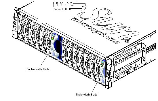
The system chassis contains 16 slots. It can hold a combination of single-width blades, double-width blades and filler panels. Double-width blades occupy two adjacent slots in the system chassis.
The existing blade or filler panel must be removed immediately prior to installing the new blade. Do not leave the blade slot empty for an extended period of time.
FIGURE 12-1 shows a system chassis containing single-width blades and a
double-width blade.
|
Note - Be aware that the system chassis contains three internal dividing walls. Double-width blades must be installed in two available slots between these internal dividing walls. |
 To shutdown the blade in preparation for removal, and to cause the blue "Ready to Remove" LED to be lit, type:
Where n is the number of the slot containing the blade you are removing.
|
Note - If the Solaris Operating environment is executing on the blade the System Controller will cause it to shut down in an orderly manner before it powers it off. |
The steps in this section refer to removal of a single-width blade. The same steps apply when installing a double-width blade or filler panel.
1. If you are removing a blade, check that the blue "Ready to Remove" LED is lit.
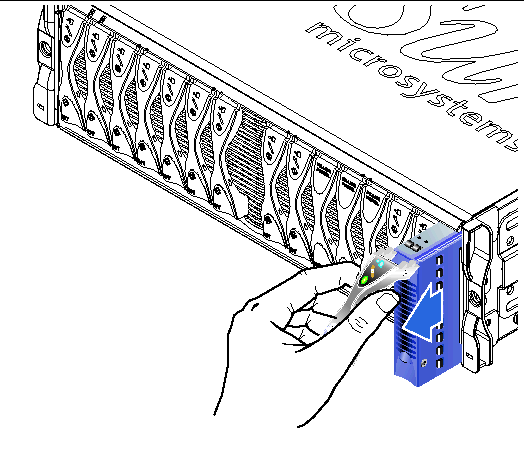
2. Insert your finger in the pull recess located at the bottom front of the blade lever and pull gently to disengage the locking mechanism (FIGURE 12-2).

3. Pull the lever in a forward and upward motion, causing the blade lever to unlatch and eject the blade partially from the system chassis (FIGURE 12-3).
4. Pull the lever to remove the filler panel from the system chassis (FIGURE 12-4).
Support the bottom of the filler panel with your free hand while lifting the filler panel clear of the system chassis.

5. Install a blade or filler panel into the empty slot.
See Section 12.1.3, Inserting the New Blade or Filler Panel.

|
Caution - Do not leave any slots empty as this can disrupt airflow through the system and compromise EMC performance. |
The system chassis is designed to operate with a total of up to 16 blades and filler panels installed.
|
Note - Be aware that the system chassis contains three internal dividing walls. Double-width blades must be installed in two available slots between these internal dividing walls. |
The steps below refer to installation of a single-width blade. The same steps apply when installing a filler panel or double-width blade.
1. If required, open the blade lever by inserting a finger in the pull recess located in lower portion of the blade lever and pull the lever in a forward and upward motion, causing the lever to unlatch (FIGURE 12-5).

2. Align the blade with the empty slot.
Ensure that the blade connector is facing towards the system chassis, with the hinge point of the lever mechanism at the top. Support the bottom of the blade with your free hand while lifting the blade up to the system chassis (FIGURE 12-6).
3. Insert the blade into the selected system chassis slot (FIGURE 12-6).

|
Caution - Ensure that the blade engages with the system chassis guidance system. Failure to align the blade correctly can result in damage to the chassis midplane or the blade connection. |

4. Gently push the blade into the slot until the blade latch ears, on top of the lever, are positioned in the chassis.
5. Close the blade lever fully by pushing it down until you feel the latch click in place.
This engages the blade with the connectors in the chassis slot (FIGURE 12-7). When you do this, the LEDs on the blade flash several times.

1. From the System Controller's sc> prompt, console into the server blade by typing:
where n is the number of the slot containing the blade you have just installed.
2. Follow the instructions in the Sun Fire B1600 Blade System Chassis Software Setup Guide for powering on the blade and loading the operating environment.
This section provides the steps required to replace an SSC in the system chassis. For information about how the chassis's midplane and the SSCs cooperate to preserve System Controller login information and server blade host ID information for the chassis as a whole, see Section 12.5, User Login and Host ID Information for a Replacement Chassis or SSC.
|
Note - When you replace an SSC, you must ensure that the latest version of the System Controller firmware is installed on the new SSC. For information on checking the System Controller version and on how to upgrade the System Controller firmware, see Chapter 10. |
|
Note - Release 1.2 is the first firmware release to support failover (in other words, to support the ability of two System Controllers to monitor each other's health, and of the standby System Controller to take over from the active one in the event of a critical failure). Therefore, before adding the new SSC module into the chassis, make sure the currently installed SSC is using release 1.2 (or later) of the System Controller firmware (see Step 3 below). If the module you are installing as a redundant SCC is not a new one but is taken from another chassis and does not have release 1.2 (or later) firmware installed on it, upgrade its firmware while it is still in the old chassis before installing it as a redundant SSC. |
The mechanical procedures for removing and installing an SSC filler module are the same as those for removing and installing an actual SSC module (except there are no LEDs to indicate when the module is ready to remove - it is always ready).
|
Note - Do not install the new SSC hardware until you have upgraded the firmware on the currently installed SSC to release 1.2 (or later). |
1. Download release 1.2 of the System Controller firmware from the following website onto a TFTP server:
http://wwws.sun.com/software/download/network.html
2. Upgrade the currently installed SSC to firmware release 1.2.
For instructions on using a TFTP server to upgrade the firmware on an SSC, see Chapter 10. A sample upgrade command is as follows:
When you complete the upgrade procedure described in Chapter 10, make sure you reset the System Controller by typing:
3. To confirm that the SSC now has the correct firmware installed (version 1.2.x), type:
4. Remove the SSC filler panel (if present) from the spare SSC slot.
For instructions on removing this, see Section 12.2.3, Removing an SSC Enclosure.
5. Insert the new SSC and wait (approximately 30 seconds) for it to boot.
For instructions on inserting an SSC module, see Section 12.2.4, Inserting the New SSC. Make sure you connect network and serial cables for the second SSC.
To confirm that the new SSC is installed and in standby mode, type showsc:
6. Check that the new standby SSC has the correct firmware installed (version 1.2.x) to support failover.
a. To do this, first make the standby SSC into the active one by using the setfailover command as follows:
c. If the newly active SSC does not have the correct firmware installed, then repeat Step 2 to upgrade the firmware.
For more information on performing a manual failover from one SSC to the other, see Chapter 7.
7. Your chassis is now operating with redundant System Controllers and switches.
If you want to revert back to using the original SSC as the active one, run the setfailover command again.
To check which of the SSCs is the active one run the showsc command again.
8. Configure the chassis to take full advantage of the network redundancy provided by the second SSC module.
For information on how to do this if you are using Solaris server blades, refer to the Sun Fire B1600 Blade System Chassis Software Setup Guide (Chapters 5, 6, and 7).
1. Make sure the SSC you are removing is the one containing the standby System Controller.
To do this, type the showsc command at the sc> promt. For example:
where the : characters indicate omitted information.
2. If the SSC you intend to remove is not the standby one, then force it to become the standby one.
Type yin response to the prompt.
3. To disable the standby SSC prior to removal, and to cause the blue "OK to remove" LED on the SSC to be lit, type:
where n is either 0 or 1 depending on which SSC you are about to remove.
1. Check that either the blue `OK to Remove`, or amber `service required` LED is lit.
|
Note - Do not remove the SSC until one of these LED states is displayed. |
2. Disconnect all network and management cables from the SSC and disengage the cables from the cable management system, if necessary.
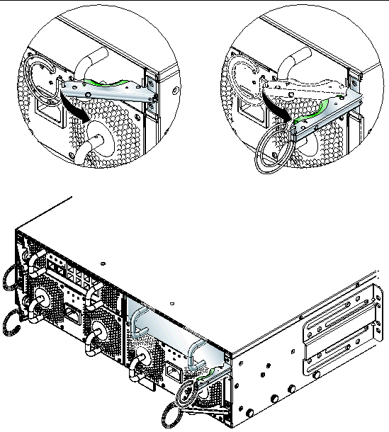
3. Squeeze the green SSC ejector lever to unlatch it, and then pull the lever towards you to disconnect the SSC from the system chassis (FIGURE 12-9).
 and a rear and side view of the chassis with arrows indicating removal of SSC1.")
4. Check that the ejector lever is open fully and clear of the SSC module (FIGURE 12-9).
5. Remove the SSC from the system chassis by pulling on the vertical handles attached to the back of the SSC (FIGURE 12-10).
Support the bottom of the SSC while removing the module from the system chassis.

1. Align the SSC with the system chassis.
SSC connectors must face towards the system chassis and be located on the lower half of the SSC.
2. Ensure that the chassis ejector lever is opened fully and does not obstruct the chassis opening (FIGURE 12-11).

3. Slide the SSC into the empty chassis slot.
Push the SSC into the slot until the ejector lever engages (FIGURE 12-12).

4. Complete insertion by closing the ejector lever.
Check that the latch engages onto the SSC pull handle. This engages the SSC into the system chassis (FIGURE 12-13).

5. Reconnect all network and management cables to the SSC and, if necessary, place the cables in the cable management system.
6. Check that the green `Activity` LED is lit.
7. Log into the active SSC and power on the new standby SSC.
where n is either 0 or 1 depending on whether you have replaced SSC0 or SSC1.
This section provides the steps required to replace a Power Supply Unit in the
Sun Fire B1600 system chassis.


|
Caution - Do not connect an IEC power cord to the Power Supply Unit until the PSU is installed. |
1. To disable the PSU prior to removal, at the sc> prompt, type:
where n is either 0 or 1 depending on whether you are removing PSU 0 or PSU 1.
1. Check that either the blue `OK to Remove`, or amber Fault LED is lit.
|
Note - Do not remove the PSU until one of these LED states is displayed. |
2. Disconnect the power cable from the PSU and disengage the cable from the cable management system, if necessary.
3. Squeeze the green PSU ejector lever to unlatch it and pull the lever towards you to disconnect the PSU from the system chassis (FIGURE 12-14).

4. Check that the ejector lever is open fully and clear of the PSU module.
5. Remove the PSU from the system chassis by pulling on the vertical handles attached to the rear of the PSU (FIGURE 12-15).
Support the bottom of the PSU while removing the module from the system chassis.


|
Caution - To ensure that it remains within an acceptable range of operating temperatures the Sun Fire B1600 system chassis requires two PSUs. |

|
Caution - Do not install a PSU with the IEC power cord already attached. Only connect the power cord when the PSU is installed. |
1. Correctly align the PSU with the empty PSU slot in the system chassis.
PSU connectors must face towards the system chassis and be located on the lower half of the PSU.
2. Check that the chassis ejector lever is opened fully and does not obstruct the opening to the PSU slot in the chassis.
3. Slide the PSU into the empty PSU slot in the chassis.
Push the PSU into the slot until the ejector lever engages (FIGURE 12-16). You must push the PSU firmly to raise the system flap within the system chassis.

4. Complete the installation by closing the ejector lever fully.
Check that the ejector lever engages onto the PSU pull handle. This engages the PSU into the system chassis (FIGURE 12-17).

5. Connect the power cable to the PSU.
6. Check that the green `Activity` LED is lit.
This section tells you how to shut down one chassis, remove its components, remove the chassis from the rack, and install the new chassis into the rack. It then tells you how to install the components from the old chassis into the new one.
This section contains the following sub-sections:
|
Note - The new chassis will use the same host ID and user login information as the old chassis. For information about the behavior of the midplane in the new chassis with respect to login information and server blade host ID information on SSCs from another (previously configured) chassis, see Section 12.5, User Login and Host ID Information for a Replacement Chassis or SSC. |
To shut down all components of the chassis that can be powered down (that is, all blades, the standby SSC, and both switches, type:

|
Caution - The PSUs provide the only reliable connection to earth for the system chassis. Do not remove the PSUs until all other components have been removed. |
We recommend you note the position of the SSCs and server blades before removing them from the old chassis. This enables you to install them into the corresponding enclosures and blade slots in the new chassis.
Remove the system components in the following order:
1. Blades and filler panels. See Removing the Existing Blade or Filler Panel.
2. SSCs. See Removing an SSC Enclosure.
3. PSUs. See Removing the Existing PSU.
1. Unscrew the system chassis captive retaining screws.
2. Slide the system chassis out of the rack (FIGURE 12-18).
The system chassis will stop when the retaining catches positioned on the chassis runners meet the rack. You must depress the retaining catches before you can remove the system fully from the rack.

1. Remove the rear brackets from the system chassis and rack (FIGURE 12-19).

2. Detach the front brackets from the rack (FIGURE 12-20).

3. Remove the front rack bracket from the system chassis (FIGURE 12-21).

For information about installing the chassis into a rack, refer to the Sun Fire B1600 Blade System Chassis Hardware Installation Guide (Part No. 816-7614). This tells you how to install into the following racks:
When the new chassis is installed in the rack, you can install the system components. Remember to install the SSC and server blades into the enclosures and blade slots that correspond with their original locations in the old chassis.
Install the chassis components in the following order:
1. PSUs. See Installing a New Power Supply Unit.
2. SSCs. See Installing a New SSC.
3. Blades and filler panels. See Installing A New Blade.
Read this information if you are replacing a chassis or if you are replacing an SSC.
Where a new SSC (in its factory default state) is introduced into a chassis that is already in use, the new SSC inherits the user login information (for the System Controllers) and the host ID information (for the server blades) that is currently stored on the midplane.
In the reverse case, where the chassis is new (and its user login and host ID information are therefore unconfigured) but the SSC has been previously in use, the midplane takes the user login and host ID information from the System Controller.
However, in the case where an SSC is introduced into a chassis and both already contain user login and host ID information but the SSC and chassis differ in respect of either or both the outcome is more complicated to predict. In this case the standby System Controller, if it is available, plays an arbitrating role. It compares its own user login and host ID information with the information held on the SSC containing the active System Controller and with the information held on the midplane. If its own host ID information agrees with that stored on either the active SSC or the midplane, then that information prevails. Similarly if its own user login information agrees with that stored on either the active SSC or the midplane, then that information prevails. For both sets of information, if the standby System Controller finds that its own information differs from that of both the active SSC and the midplane, then the information in the midplane prevails.
| Sun Fire B1600 Blade System Chassis Administration Guide
|
817-3432-12 |
Copyright © 2004, Sun Microsystems, Inc. All rights reserved.