| Exit Print View | |
Sun Blade 6000 Disk Module Administration Guide |

|
1. Overview of Using Sun Blade 6000 Disk Modules With Server Modules
Overview of the Sun Blade 6000 Disk Module
Sun Blade 6000 Disk Module Front Panel
2. Inserting, Moving and Replacing the Sun Blade 6000 Disk Module
5. Installing, Removing or Replacing Disks
7. How LSI Host Bus Adapters Assign Target IDs to Expanders, Disks, and RAID Volumes
8. How Adaptec Host Bus Adapters Assign Target IDs to Expanders, Disks, and RAID Volumes
9. Setting Up Hardware RAID Volumes With LSI and Adaptec Host Bus Adapters
10. ILOM For the Sun Blade 6000 Disk Module
11. Oracle's Sun Storage Common Array Manager (CAM)
A. Using the SIA Application to Upgrade x86 Server Blade and Host Bus Adapter Firmware
C. Upgrading the Disk Module to Allow a SAS-2 Compatible Server Blade in the Chassis
This chapter contains the following topics:
The following terminology is used in this document.
|
Note - From time to time, this document refers to SAS-NEMs. SAS-NEM is a general category: it includes Sun Blade 6000 Multi-Fabric NEMs, as well as other NEMs with SAS connectivity such as the Sun Blade 6000 10GbE Multi-Fabric NEM. From the standpoint of connecting server blades with disk blades, all SAS-NEMs provide the same functionality.
The Sun Blade 6000 Disk Module is a SAS-1 (up to 3 Gb/s data transfer speed) disk module for the Sun Blade 6000 Modular System.
As a disk module, the Sun Blade 6000 Disk Module does not contain a CPU or service processor. It does, however, contain SAS expanders, which are switching circuits that can connect disks in complex patterns.
A fully loaded Sun Blade 6000 Disk Module consists of eight SAS disks, with each disk connected to SAS expanders. The SAS expanders, in turn, connect to a Sun Blade 6000 Modular System chassis’ SAS-NEMs.
The disk module works only with a SAS-NEM. It does not work with a NEM that lacks SAS connectivity. For the disk module to function, there must be a SAS-NEM in at least slot NEM 0. Dual paths to SAS disks require SAS-NEMs in both NEM slots.
Note - You can use a plain NEM (one without SAS connectivity) in slot NEM 1, but not in slot NEM 0. If you do this, you lose the redundant second path to SAS disks.
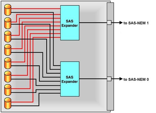
![]() Main Components of the Sun Blade 6000 Disk Module shows a schematic view of the disk module. Each SAS port connects to a single SAS-NEM module.
Main Components of the Sun Blade 6000 Disk Module shows a schematic view of the disk module. Each SAS port connects to a single SAS-NEM module.
Note - SATA drives are not supported for the disk module at this time.
![]() Interior of the Sun Blade 6000 Disk Module shows the interior of the disk module, fully loaded with eight SAS disks.
Interior of the Sun Blade 6000 Disk Module shows the interior of the disk module, fully loaded with eight SAS disks.
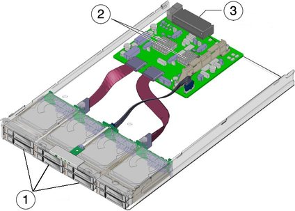
Figure Legend
1 Disk drives
2 SAS Expanders
3 Connectors to chassis midplane
The front panel of the disk module is shown in ![]() Sun Blade 6000 Disk Module Front Panel.
Sun Blade 6000 Disk Module Front Panel.
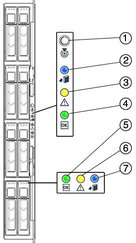
Refer to ![]() Front Panel LED Functions for descriptions of the LED behavior.
Front Panel LED Functions for descriptions of the LED behavior.
|
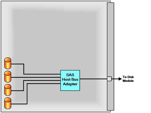
The disks on a Sun Blade 6000 Disk Module are controlled by a SAS host bus adapter on the server module. This adapter can be either an on-board chip or a RAID Expansion Module (REM) card. ![]() Connection of SAS Host Bus Adapter for Sun Blade Servers shows the key components of a server that are used to control disks. All of the server modules except the X6450 (no disks) and the T6340 (two disks maximum) can have up to four disks of their own. The SAS host bus adapter on the server module controls its own disks as well as disks on the disk module. The disks on the disk module can be connected to the SAS host bus adapter through two SAS-NEM modules, providing a dual path to each SAS disk.
Connection of SAS Host Bus Adapter for Sun Blade Servers shows the key components of a server that are used to control disks. All of the server modules except the X6450 (no disks) and the T6340 (two disks maximum) can have up to four disks of their own. The SAS host bus adapter on the server module controls its own disks as well as disks on the disk module. The disks on the disk module can be connected to the SAS host bus adapter through two SAS-NEM modules, providing a dual path to each SAS disk.
Note - Server modules with a SAS-2 (up to 6 Gb/s data transfer speed) REM are not supported to work with the Sun Blade 6000 Disk Module. However, SAS-1 NEMs and Sun Blade 6000 Disk Modules might need to be upgraded to allow a server module with a SAS-2 REM to coexist in the chassis with a SAS-1 devices. For more information, refer to ![]() Appendix C, Upgrading the Disk Module to Allow a SAS-2 Compatible Server Blade in the Chassis.
Appendix C, Upgrading the Disk Module to Allow a SAS-2 Compatible Server Blade in the Chassis.
The Sun Blade 6000 Disk Module can interoperate with any one of the supported server blades (see ![]() Chapter 3, System Requirements).
Chapter 3, System Requirements).
The server blades and disk blades must be placed in the chassis in pairs. The pairs must be in slots 0+1, 2+3, 4+5, 6+7, or 8+9. No other combination of slots can be used. A server blade in slot n (n is an even number) sees its own on-blade disks and all the disks in a disk blade in slot n+1, but no other disks.
Note - You should place the disk module in an odd-numbered slot. The server module that controls its disks should then be in the even-numbered slot to the left of the disk module. The 10 chassis slots are numbered 0 through 9 from the left to the right, viewed facing the chassis.
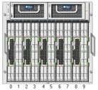
![]() Front View of Chassis Filled With Server Modules and Disk Modules in Pairs shows a Sun Blade 6000 Modular System chassis, fully loaded with server modules and disk modules.
Front View of Chassis Filled With Server Modules and Disk Modules in Pairs shows a Sun Blade 6000 Modular System chassis, fully loaded with server modules and disk modules.
