| C H A P T E R 1 |
|
Setting Up the Server Hardware |
This chapter describes how to insert the Sun Blade X6240 server module into the chassis, how to power on and power off the server module, and how to connect the dongle cable to the server module.
This chapter contains the following topics:
Note the following terms used in this book:
After unpacking your server module, perform the following tasks:
1. Insert the server module into the chassis.
See Inserting the Server Module.
2. Connect all cables, peripherals, and power cords to the chassis.
See the installation guide for your chassis.
3. Power on the server module.
See Powering On and Powering Off the Server Module.
4. Connect to the server module through the service processor on the chassis management module or through the service processor on the server module itself.
This book assumes that the service processor software on the chassis, called the CMM ILOM, is already configured. See Chapter 2, Setting Up the Server Software of this guide.
5. Configure either the preinstalled Solaris or OpenSolaris Operating System, or install a supported operating system of your choice.
Refer to Configuring the Preinstalled Solaris 10 Operating System or Configuring the Preinstalled OpenSolaris Operating System. See also the Sun Blade X6240 Server Module Operating System Installation Guide (820-3969).
6. Customize your server, as needed.
For more information, see the Sun ILOM documentation:
|
1. Locate the desired server module slot in the chassis.
2. (Optional) Remove the slot filler panel, if applicable.
Pull the lever out and eject the filler panel.
| Note - Other filler panels should remain in any unused slots as they ensure the chassis complies with FCC limits on electromagnetic interference (EMI). |
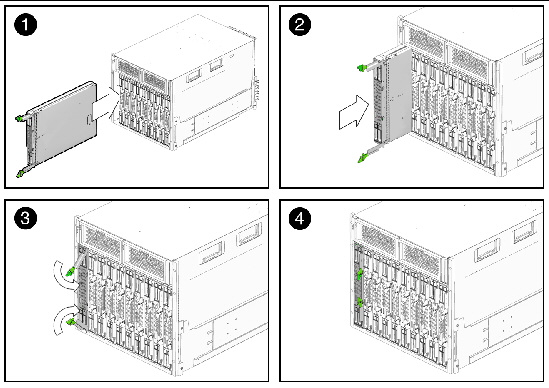
3. Position the server module vertically so that the ejectors are on the right and extended outwardly.
The following illustrations show the server module being inserted into the Sun Blade 6000 Modular System; your chassis might differ. See box 1 in FIGURE 1-1.
FIGURE 1-1 Inserting the Server Module Into the Chassis

4. Push the server module into the slot until the server module stops.
See Box 2 in FIGURE 1-1.
5. Rotate the ejectors down until they snap into place.
The server module is now flush with the chassis and the ejectors are locked. See Boxes 3 and 4 in FIGURE 1-1.
You have to apply only standby power to the server module at this point so that you can perform initial configuration of the service processor (SP). Procedures for powering on to main power mode and for shutting down from main power mode are also included in this section.
|
Use this procedure to apply standby power to the service processor (SP) before initial configuration.
1. Connect grounded AC power cords to the AC power connectors on the back panel of the chassis and to grounded AC power outlets. For details, see your chassis documentation.
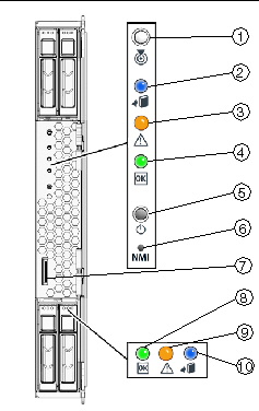
In standby power mode, the blue (Ready to Remove) LED is illuminated, indicating that the SP is working. See FIGURE 1-2 for the LED location.
| Note - At this point, standby power is supplied only to the service processor and power supply fans. |
2. Continue with initial software setup tasks, as described in Chapter 2 of this guide.
|
1. Verify that standby power is on.
In standby power mode, the blue (Ready to Remove) LED is illuminated. See FIGURE 1-2.
2. Use a pointed object or stylus to press and release the recessed Power button on the server module front panel.
When main power is applied to all server module components, the green Power LED above the Power button lights and remains lit.
FIGURE 1-2 Sun Blade X6240 Server Module Front Panel

|
To power off the server module from main power mode, use one of the following two methods:
When main power is off, the blue (Ready to Remove) LED on the front panel will be illuminated, indicating that the server module is in standby power mode.
| Note - To power off the server module completely, you must disconnect the AC power cords from the back panel of the chassis. This will remove power from all the blades in the chassis. |
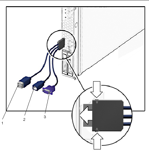
Your chassis ships with a dongle cable. The dongle enables you to plug devices directly into the front of the server module for testing.
|
1. Insert the dongle cable into the universal connector port (UCP) on the server module front panel. See FIGURE 1-3.
2. Connect device to the dongle cable connections, as appropriate.
FIGURE 1-3 Dongle Cable Connections

Copyright © 2009 Sun Microsystems, Inc. All rights reserved.