| C H A P T E R 4 |
|
Maintaining the Sun Blade X6440 Server Module |
This chapter contains information and procedures for servicing the Sun Blade X6440 server module hardware, including component removal and replacement procedures.
The following topics are covered in this chapter:
You can service the server with the following items:
Use the preparatory procedures in this section when you are referred to them from the removal and replacement procedures.

|
Caution - Do not operate the system with empty slots. Always insert a filler into an empty slot to reduce the possibility of system shut down. |
To replace components for the Sun Blade X6440 server module, you need to remove the server module from the chassis.
1. Choose a method for shutting down the server from main power mode to standby power mode.
See FIGURE 1-1 for the location of the power button.
At the ILOM command prompt, type:
See the Sun Integrated Lights Out Manager 2.0 User’s Guide (820-1188) for more information.
When the main power is off, the Power/OK LED on the front panel begins flashing, indicating that the server is in standby power mode.
2. Turn off any peripheral devices connected to the dongle, and disconnect the dongle from the server.
FIGURE 4-1 Removing a Server Module
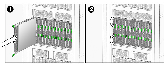
3. Remove the server module from the chassis. See FIGURE 4-1.
a. Press together and hold the green ejector buttons.
b. Open the ejector levers by rotating them out from the server module.
c. Pull the server module out from the chassis by the ejector levers until you are able to grasp the module with both hands to pull it out of the chassis.
4. Set the server module on an antistatic surface.
5. Install a filler panel into the server module slot if the server module will be out of the chassis for more than one minute.
1. Press down on the cover release button and, using the indent for leverage, slide the main cover toward the rear of the chassis approximately 0.5 inch (12 mm). See FIGURE 4-2.
2. Grasp the cover by its rear edge and lift it straight up from the chassis.
FIGURE 4-2 Removing the Main Cover
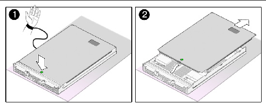
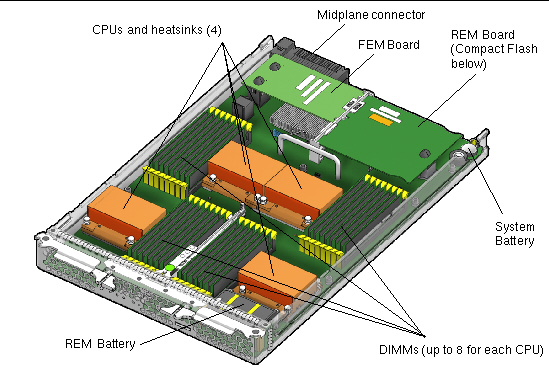
FIGURE 4-3 shows the locations of the replaceable Sun Blade X6440 server module components that are documented in this chapter.
FIGURE 4-3 Sun Blade X6440 Server Module Replaceable Component Locations
Supported components and their part numbers are subject to change over time. For the most up-to-date list of replaceable components for the Sun Blade X6440 server module, see the following URL:
http://sunsolve.sun.com/handbook_pub/Systems/
1. Click the name and model of your server.
2. On the product page that opens for the server, click the Full Components List for the list of components.
Some Sun Blade X6440 server module components are hot-swappable, which means that you can remove and replace those components without powering off the server module. For other component replacements, you must power off and remove the server module from the chassis.
This section contains procedures for replacing the following components:
| Note - This component is a CRU and can be replaced by anyone. |
Use the following procedure to replace the server module system battery.
1. Power off the server and remove the server module from the chassis as described in Removing the Server Module From the Chassis.

|
Caution - Do not operate the system with empty slots. Always insert a filler panel into an empty slot to reduce the possibility of system shut down. |
2. Remove the main cover as described in Removing the Main Cover.
3. If a RAID expansion module (REM) card is installed in the server module, it must be removed before extracting the system battery. For instructions, see Adding or Replacing a RAID Expansion Module.
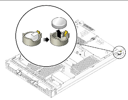
4. Remove the system battery by gently pulling the clip away from the side of the battery and lifting the battery from its holder. See FIGURE 4-4.
FIGURE 4-4 Removing the System Battery
Installation is the reverse of these procedures.
| Note - Install the new system battery in the holder with the same orientation (polarity) as the battery that you removed. The positive polarity, marked with a “+” symbol, should be facing upward. |
| Note - This component is a CRU and can be replaced by anyone. |
Use the following procedure to replace the compact flash module.
1. If necessary, back up any data that is contained on the Compact Flash module.
2. Power off the server and remove the server module from the chassis as described in Removing the Server Module From the Chassis.

|
Caution - Do not operate the system with empty slots. Always insert a filler panel into an empty slot to reduce the possibility of system shut down. |
3. Remove the main cover as described in Removing the Main Cover.
4. Locate the Compact Flash module underneath the REM board. See FIGURE 4-5.
You do not need to remove the REM board to remove the Compact Flash module.
FIGURE 4-5 Replacing the Compact Flash Module
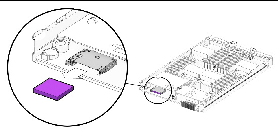
5. Push the compact flash ejector button to release the module from its holder.
This action causes the spring-loaded card to eject.
6. Grasp the compact flash module and pull it out from under the REM board.
Installation is the reverse of this procedure.
Use the procedures in this section to remove and replace the server’s dual inline memory modules (DIMMs).
The DIMM population rules for the Sun Blade X6440 server modules are listed here:
| Note - This component is a CRU and can be replaced by anyone. |
Use the following procedure to replace a DIMM.
1. Power off the server and remove the server module from the chassis as described in Removing the Server Module From the Chassis.

|
Caution - Do not operate the system with empty slots. Always insert a filler panel into an empty slot to reduce the possibility of system shut down. |
2. Remove the main cover as described in Removing the Main Cover.
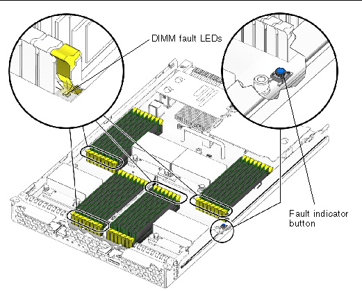
3. Press the fault indicator button on the motherboard to illuminate the LED for the DIMMs that have failed.
FIGURE 4-6 Fault Indicator Button Location
4. Locate the DIMM slot on the motherboard into which you plan to install or replace a DIMM.
The DIMM ejector levers contain LEDs that can indicate a faulty DIMM:
FIGURE 4-7 Sun Blade X6440 Server Module DIMM Slot Numbering
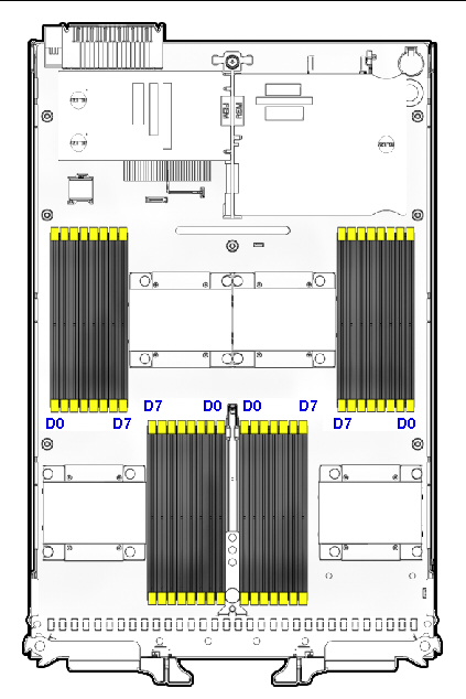
5. Before continuing with the next step, review the guidelines in DIMM Population Rules.
a. Rotate both DIMM slot ejectors outward as far as they will go. The DIMM is partially ejected from the socket. See FIGURE 4-8.
b. Carefully lift the DIMM straight up to remove it from the socket.
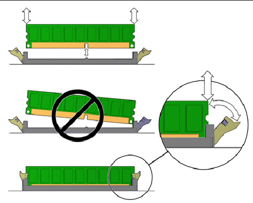
a. Ensure that the DIMM slot ejectors at each end of the memory socket are fully open (rotated outward) to accept the new DIMM.
b. Align the notch in the bottom edge of the DIMM with the key in the DIMM socket. See FIGURE 4-8.
c. Press down evenly on both top corners of the DIMM until the ejectors snap over the cutouts in the left and right edges of the DIMM.
The AMD processor on the Sun Blade X6440 server module provides parity protection on its internal cache memories and error-correcting code (ECC) protection of the data. The system can detect and log to the system event log (SEL) the following types of errors:
Advanced ECC corrects up to 4 bits in error on nibble boundaries, as long as they are all in the same DRAM. If a DRAM fails, the DIMM continues to function.
Refer to the Sun Integrated Lights Out Manager 2.0 User’s Guide (820-1188) for more information on accessing the error log.
Follow these steps to remove and replace a RAID expansion module (REM) in a Sun Blade X6440 server module.
The RAID expansion module enables LSI RAID functionality for externally attached RAID arrays and hard disk drives (HDDs).
| Note - For information on configuring external RAID arrays and HDDs, see the instructions that shipped with the product. |
| Note - This component is a CRU and can be replaced by anyone. |
Use the following procedure to add, or remove and replace the REM.
1. Power off the server and remove the server module from the chassis as described in Removing the Server Module From the Chassis.

|
Caution - Do not operate the system with empty slots. Always insert a filler panel into an empty slot to reduce the possibility of system shutdown. |
2. Remove the main cover as described in Removing the Main Cover.
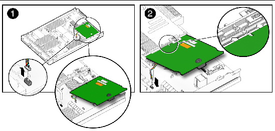
3. If the REM board uses a backup battery, (see also Changing the REM Battery) disconnect the jumper cable between the REM board and chassis motherboard.
The Sun Blade X6440 can be populated either with REM board model 4620A, which uses a backup battery to store the system configuration, or REM board model 4607A, which does not use a backup battery.
4. Remove the existing REM board or the cap(s) from the REM connector(s) if either is present.
The cap(s) should only be present if you are adding a REM board to a server module without one.
5. Slide the REM board at an angle into the support bracket, then press it carefully into the connector. See FIGURE 4-9.
6. If the REM board uses a backup battery, connect the jumper cable between the REM board and chassis motherboard.
Installation is the reverse of this procedure.
The REM battery, used with board model 4620A, should be replaced when indicated in the Sun StorageTek RAID Manager Software User's Guide (820-1177).

|
Caution - Follow the instructions in this section to ensure that the REM battery is properly installed. Proper installation is required to ensure adequate cooling of the battery. |
| Note - This component is a CRU and can be replaced by anyone. |
Use the following procedure to change the REM battery.
1. Power off the server and remove the server module from the chassis as described in Removing the Server Module From the Chassis.

|
Caution - Do not operate the system with empty slots. Always insert a filler into an empty slot to reduce the possibility of module shutdown. |
2. Remove the main cover as described in Removing the Main Cover.
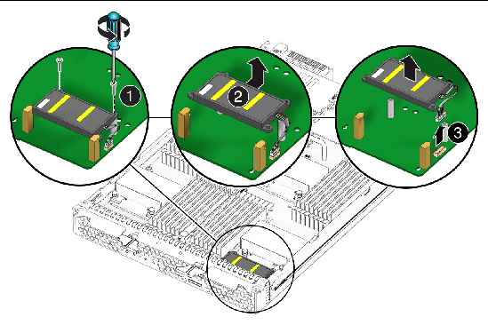
3. Remove the two screws that secure the REM battery to the battery standoff connectors.
4. Lift the battery away from the standoff connectors while simultaneously pulling the battery from its slot.
5. Disconnect the battery cable from the chassis motherboard. See FIGURE 4-10.
6. To install the new battery, reverse Step 1 through Step 5.
FIGURE 4-10 Replacing the REM Battery
Follow these steps to remove and replace a Fabric Expansion Module (FEM) in a Sun Blade X6440 server module.
| Note - This component is a CRU and can be replaced by anyone. |
Use the following procedure to add, or remove and replace the FEM.
1. Power off the server and remove the server module from the chassis as described in Removing the Server Module From the Chassis.

|
Caution - Do not operate the system with empty slots. Always insert a filler panel into an empty slot to reduce the possibility of system shutdown. |
2. Remove the main cover as described in Removing the Main Cover.
3. Remove the existing FEM board or the cap from the FEM connector if either is present.
The cap should only be present if you are adding a FEM board to a server module without one.
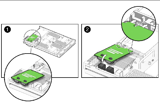
4. Slide the FEM board at an angle into the support bracket, then press it carefully into the connector. See FIGURE 4-11.
Installation is the reverse of these procedures.
FIGURE 4-11 Inserting the FEM Board
| Note - This component is a FRU and should be replaced only by qualified service technicians. Contact your Sun service representative for assistance. |
Follow these steps to remove and replace a CPU and its heatsink in a Sun Blade X6440 server module.
1. Power off the server and remove the server module from the chassis as described in Removing the Server Module From the Chassis.

|
Caution - Do not operate the system with empty slots. Always insert a filler panel into an empty slot to reduce the possibility of system shut down. |
2. Remove the main cover as described in Removing the Main Cover.
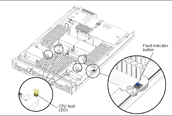
3. Press the fault indicator button on the motherboard to illuminate the LED for the CPU that has failed.
FIGURE 4-12 Fault Indicator Button Location
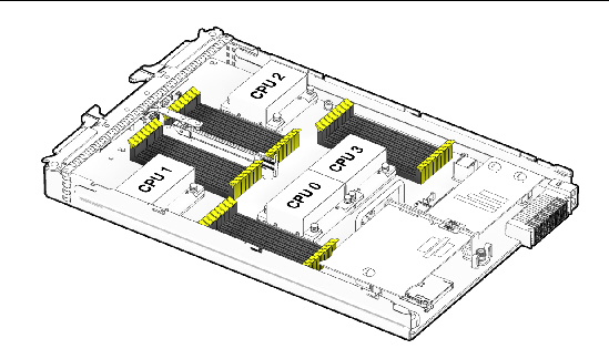
4. Identify which CPU and heatsink you are replacing.
The internal designation of the two CPUs in the server is shown in FIGURE 4-12. There is a fault LED on the motherboard for each CPU:
5. Remove the CPU and heatsink from the motherboard:
a. Hold down on the top of the heatsink to prevent it from tipping unevenly while you alternately loosen the four spring-loaded mounting screws that secure the heatsink to the motherboard.
Turn the screws 180 degrees at a time, and then remove the screws when they are detached. See FIGURE 4-14.
FIGURE 4-14 Removing the Heatsink and CPU
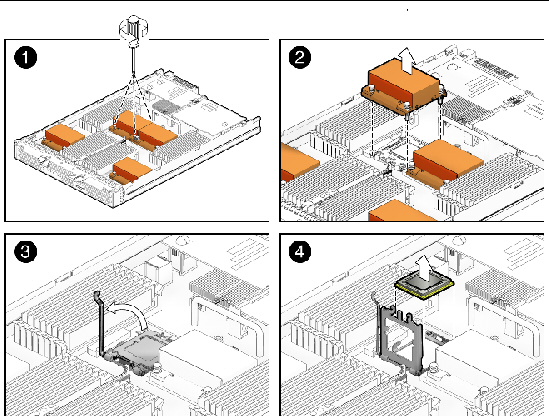
b. Twist the heatsink slightly to lift it off the board. Turn the heatsink upside down and allow the spring in each of the four mounting holes to fall out into your hand.
| Note - Set the heatsink upside down on a clean, flat surface to prevent the thermal grease from contaminating other components. |
6. Pull the CPU socket lever slightly away from the socket.
a. Pivot the lever up, into the fully open position.
b. Open the hinged plate that covers the CPU until it is in the fully open position.
c. Lift the CPU out of the socket, leaving the lever and plate in the open position.
7. Install the new CPU, or reinstall the existing CPU.
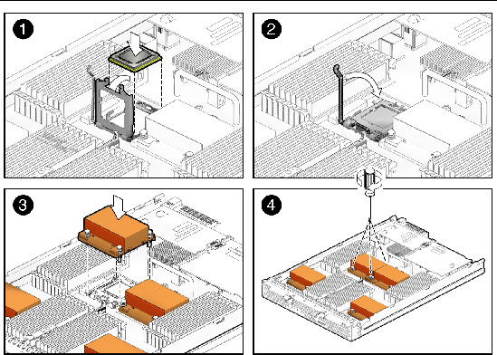
FIGURE 4-15 shows how to install the CPU and heatsink.
FIGURE 4-15 Installing the Heatsink and CPU
| Note - Mixing CPU speeds is not supported. Use two identical CPUs in your server. |
a. If you are reinstalling the existing CPU, use an alcohol pad to clean all the old thermal grease from the component surface.
You will need to apply new thermal grease when you reinstall the heatsink in Step 8.
b. Ensure that the CPU socket release lever and retainer plate are in the fully open position.
c. Align the CPU in the socket.
| Note - Use the alignment keys in the CPU socket to match the alignment notches on the sides of the CPU. |
d. Gently set the CPU onto the pins in the socket.
e. When the CPU is fully seated in the socket, pivot the hinged retainer plate down onto the top of the CPU.
f. Pivot the release lever down and into the locked position, at the side of the socket.
The release lever must lock down the retainer plate as you close the lever.
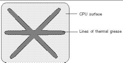
a. Using one syringe of thermal grease (0.2 ml/0.5 g), carefully apply grease to the top of the CPU in three lines in the pattern shown in FIGURE 4-16.
FIGURE 4-16 Required Pattern for Thermal Grease Application
b. If you are reinstalling an existing heatsink, use an alcohol pad to clean all the old thermal grease from the component surface. Also, clean the dust from the heatsink fins.
c. Turn the heatsink upright and reinsert the four springs and mounting screws.

|
Caution - Avoid moving the heatsink after it has contacted the top of the CPU. Too much movement could disturb the layer of thermal grease, leading to component damage. |
d. Carefully position and align the heatsink over the CPU.
e. Lower the heatsink onto the CPU, aligning the mounting screws with their holes on the motherboard.
f. Using an adjustable torque driver, alternately tighten the two heatsink mounting screws, 180 degrees at a time, until each spring is completely compressed.
Tighten the screws to 7 in.-lbs (0.8 Nm).
| Note - This component is a FRU and should be replaced only by qualified service technicians. Contact your Sun Service representative for assistance. |
Follow these steps to remove and replace the motherboard.
1. Remove the server module from the chassis as described in Removing the Server Module From the Chassis.

|
Caution - Do not operate the system with empty slots. Always insert a filler panel into an empty slot to reduce the possibility of system shut down. |
2. Remove the main cover as described in Removing the Main Cover.
3. Remove the following components from the motherboard and place them on an antistatic surface.
| Note - The server module enclosure, and the motherboard are all part of the motherboard FRU. |
Installation is the reverse of this procedure.
Copyright © 2009 Sun Microsystems, Inc. All rights reserved.