| C H A P T E R 3 |
|
Exploring the Software |
Before you build a storage space, read this chapter to familiarize yourself with the main features of the Sun StorageTek RAID Manager software and learn to navigate to the information you need.
This chapter contains the following sections:
The main window of the Sun StorageTek RAID Manager software has three main panels, or views, in addition to the other features shown in this figure.
FIGURE 3-1 Sun StorageTek RAID Manager Main Window
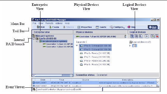
Resize the panels and scroll horizontally or vertically as required, to view more or less information.
For more information about specific areas of the main window, see these sections:
The Enterprise View is an expandable tree with two main branches--the Internal RAID branch, and the External RAID branch. The External RAID branch is not covered in this document.
Under Internal RAID, the Enterprise View lists the local system (the system you are working on) and any other systems that you are managing using the Sun StorageTek RAID Manager software.
Expand a system in the Enterprise View to the see its HBAs. (See Logging Into Remote Systems for more information about local and remote systems.)
| Note - See Creating Display Groups to learn how to group related systems together in the Enterprise View. |
When you select a component in the Enterprise View, the disk drives and logical drives (“devices”) associated with it appear in the Physical and Logical Devices Views, as shown in the following figure.
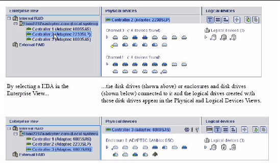
You can perform most tasks by selecting an HBA in the Enterprise View and working with its associated devices in the Physical and Logical Devices Views.
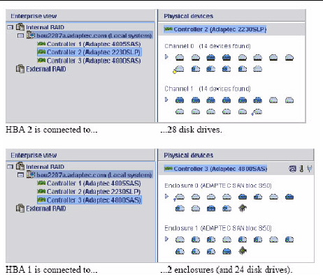
When you select an HBA in the Enterprise View, information about the physical disk drives and enclosures connected to that HBA are displayed in the Physical Devices View.
FIGURE 3-3 Example of the Physical Devices View
|
|
Disk drives designated as hot-spares have plus signs (+) beside them. A blue plus sign means that the spare is protecting at least one logical drive. See Working With Hot-Spares for more information. |
|
|
A hot-spare with a yellow plus sign may not be large enough to protect the logical drive it’s assigned to, or may not be assigned to a logical drive. See Working With Hot-Spares for more information. |
|
|
Hold your cursor over any disk drive to see its status, port/connector/ID number, and maximum speed. You can also click the arrow to see this same information for all the disk drives at the same time. To reveal further information, use the View buttons to change how the disk drives are displayed, as described in Revealing More Disk Drive Information. |
|
|
A disk drive shaded in light blue is not part of any logical drive. A disk drive shaded half light/half dark blue has some space allocated to a logical drive, and some space available. To view the logical drives associated with a particular disk drive, see Using the Logical Devices View. |
|
|
If your storage space includes an enclosure, its enclosure management device is represented by the following icon. |
When you select an HBA in the Enterprise View, information about the logical drives and arrays associated with that HBA appear in the Logical Devices View. (A logical drive is a group of physical disk drives that your operating system recognizes as a single drive. For more information, see Understanding Logical Drives.)
FIGURE 3-4 Logical Devices View
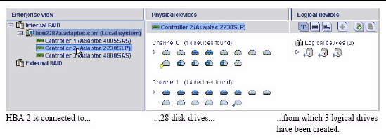
Click on a logical drive to highlight the disk drives that comprise it in the Physical Devices View.In the following figure, six disk drives (plus one hot-spare) comprise the selected RAID 5 logical drive.
FIGURE 3-5 Relationship Between Physical and Logical Devices
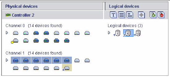
You can also click on any disk drive to see which (if any) logical drive it belongs to. A disk drive shaded in light blue is not part of any logical drive.
You can reveal more information about disk drives by using the View buttons to change how they are displayed.
By default, disk drives are displayed in the unexpanded Text Description View, as shown in the following figure.
FIGURE 3-6 Unexpanded Text Description View

Or, if you are managing disk drives in an enclosure, the disk drives are displayed in the Enclosure View.

| Note - Not all enclosures are supported by the Sun StorageTek RAID Manager software. Unsupported enclosures do not appear in Enclosure View. |
Click the expand arrow to see basic disk drive information.
FIGURE 3-8 Text Description View

Click the Full Size Capacity View button to see the size capacities of the disk drives. Disk drives or segments of disk drives that are included in logical drives are shaded brown.
FIGURE 3-9 Full Size Capacity View

Click the Relative Size Capacity View button to see the size capacities of the disk drives relative to each other. A full length bar is displayed for the largest disk drive. Proportionally shorter bars are displayed for other disk drives.
FIGURE 3-10 Relative Size Capacity View

The Sun StorageTek RAID Manager software includes an Event Viewer for at-a-glance system and event status information. The Event Viewer provides status information and messages about activity (or events) occurring in your storage space. Double-click any event to see more information in an easier-to-read format.
FIGURE 3-11 Event Viewer Screen

Warning- and Error-level icons, shown in FIGURE 3-12, appear next to components (such as systems and logical drives) affected by a failure or error, creating a trail, or rapid fault isolation, that helps you identify the source of a problem when it occurs. See Identifying a Failed or Failing Component for more information.
FIGURE 3-12 Enclosure Warning and Disk Drive Error Icons

If your storage space includes a HBA with a temperature sensor, or an enclosure with an enclosure management device, such as a SCSI Accessed Fault-Tolerant Enclosure (SAF-TE) processor, temperature, fan, and power module status is displayed by status icons in the Physical Device view, as shown in the next figure. These status icons change color to indicate status (see Managing Enclosure Status).
FIGURE 3-13 Physical Devices View Icons

For more information, see Monitoring Storage Space.
| Note - By default, all Warning- and Error-level events activate an audible alarm. See Silencing and Testing the Audible Alarm for more information. |
The Sun StorageTek RAID Manager software provides multiple ways to work with its menus and windows.
Most menu options are available by doing the following:
For simplicity, the tasks in this document are explained mainly using menu bar options.
Most of the main tasks in the Sun StorageTek RAID Manager software are part of the Actions menu on the menu bar. Options on the Actions menu vary, depending on which type of component is selected in the main window. For instance, managed systems, disk drives, and hot-spares each have specialized Actions menus.
For an overview of all Actions menu options, see About Viewing Actions Menu Options.
The Sun StorageTek RAID Manager software online Help includes conceptual information, glossary definitions, and descriptions of on-screen menus and items, in addition to step-by-step instructions for completing tasks.
To open the online Help, click the Help button. Alternatively, press the F1 key, or in the menu bar select Help, then click Search or Contents.

Press the Help button in a dialog box or wizard for help with that specific dialog box, window, or procedure.
Additionally, you can find the most commonly asked-about information in Frequently Asked Questions of this document. For help identifying features of the Sun StorageTek RAID Manager software, see Buttons and Icons At-a-Glance.
Copyright © 2009 Sun Microsystems, Inc. All rights reserved.