Policy Rules Panel
Policy rules govern data communication between systems--either another host, a network, or a remote computer and your network. You write and edit the rules that govern this communication in the Policy Rules panel. SunScreen uses ordered sets of rules to implement the security policies. Ordered set of rules means that, when a Screen receives a packet, it matches the packet against each rule in its active policy until it finds one that applies, and then takes the actions associated with that rule. Once a Screen finds an applicable rule for a packet, it ignores subsequent rules in its active policies.
Rules do not take effect until you save and activate the policy to which they belong by clicking the Save Changes button located above the Common Objects area, and the Activate button in the bottom area of the Policies List page. SunScreen sets up the basic security policy for name service lookups, Routing Information Protocol (RIP) packets, and SunScreen SKIP certificate discovery during installation. You can change these setting for each Screen by changing them in the screen object. You can use the Rules area on the Policy Rules page to specify how your Screen should filter other types of packets.
Note -
If the specified filtering rule fails to detect any issued certificate (key) encryption algorithms, it may display the following error message: An error occurred in detecting the Encryption algorithms. Please check if skipd process is running. If this occurs, restart the skipd process using the command skipd_restart.
Use the Policy Rules panel to add or modify a rule in a SunScreen policy. Clicking the Add New button (or selecting a policy and clicking the Edit button) opens the Policy Rules panel of the Policy List page.
To display the controls on a tab, click the tab header. TABLE 5-34 describes the tabs that are available from the Policy Rules panel.
Table 5-34 Policy Rules Panel Tabs|
Tab |
Description |
|---|---|
|
Packet Filtering |
Shows the packet filtering rule or rules. |
|
Administration Access |
Defines access rules for local administration and remote Administration Stations through the administration GUI or the command line (seeAppendix B, Command-Line Reference ). |
|
NAT (Network Address Translation) |
Maps private network addresses to public network addresses. |
|
VPN (Virtual Private Network) |
Maps name, address, certificate, issued certificate (key) algorithm, data algorithm, MAC algorithm, tunnel address, and description. |
Packet Filtering Tab
The Packet Filtering tab displays a panel, shown in FIGURE 5-34, for configuring packet-filtering rules. Use packet filtering to control traffic using a particular service, traffic intended for a particular service, or traffic coming from a particular address.
Figure 5-34 Packet Filtering Tab
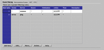
SunScreen uses ordered packet filtering. The Screen assumes that the first rule that matches a packet is the rule that governs the disposition of the packet.
If the packet does not match any rule, the Screen uses its default action to determine the disposition of the packet.
Note -
The default action is set when defining the interfaces. A default action can be set for each interface, but not for the entire Screen. Typically, the default action is to only drop the packet. Other options are available. See "Interface".
TABLE 5-35 describes the available fields in the Packet Filtering tab.
Table 5-35 fields on the Packet Filtering Tab|
Field |
Description |
|---|---|
|
Rule Index |
(Optional) Assigns a number to a rule. When editing or adding a new rule, by default, this field displays a number one greater than the last rule (indicating this rule will be placed at the bottom of the list). If you type a lower number, the new rule is inserted into the specified position in the list, and the rules currently in the configuration are renumbered. |
|
Screen |
(Optional) Specifies the Screen for which you want the rule to apply. Type a specific Screen name in this field if you use centralized management and want a rule to apply to a specific Screen. |
|
Service |
Identifies the network service or service group to which this rule applies. Network services and service groups are described in Appendix C, Services and State Engines. |
|
Source |
The value to which the source address of a packet is compared. If an asterisk (*) appears, any source address meets the criteria of the rule. |
|
Destination |
The value to which the destination address of a packet is compared to determine whether the rule should apply. If an asterisk (*) appears, any destination address meets the criteria of the rule. |
|
Action |
Displays the action for the rule and permits setting the logging behavior. The options are:
|
|
Time |
Specifies the time of day for the rule. |
|
Description |
(Optional) Provides a brief description of the Administrative Access rule. |
To edit every field, except the Rule Index field, on the Packet Filtering tab, click it to display the choice list. The changes in the fields for a rule are reflected in the Common Objects panel, except for the Action field, which displays a dialog box for that rule and policy. Set the logging options for the action in the dialog box for that action. The particular dialog box that appears depends on the action selected.
ALLOW Action
FIGURE 5-35 shows the Policy Rule Index dialog box for the ALLOW action.
Figure 5-35 Policy Rule Index Dialog Box for ALLOW action

TABLE 5-36 describes the controls in Policy Rule Index dialog box for ALLOW action.
Table 5-36 Controls for ALLOW Action
-
PROXY_HTTP - Presents the dialog box shown in FIGURE 5-36.
Figure 5-36 PROXY_HTTP Dialog Box for ALLOW action
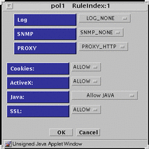
TABLE 5-37 lists the flags for the HTTP proxy.
Table 5-37 HTTP Proxy Flags
-
PROXY_FTP - Presents the dialog box shown in FIGURE 5-37.
Figure 5-37 PROXY_FTP Dialog Box for ALLOW action
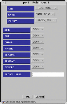
TABLE 5-38 lists the settings available for the flags for the FTP proxy.
Table 5-38 FTP Proxy Flags|
Flag |
Function |
|---|---|
|
GET |
Allow or disallow use of the FTP get command |
|
PUT |
Allow or disallow use of the FTP put command |
|
CHDIR |
Allow or disallow use of the FTP chdir command |
|
MKDIR |
Allow or disallow use of the FTP mkdir command |
|
RENAME |
Allow or disallow use of the FTP rename command |
|
REMOVE |
Allow or disallow use of the FTP remove_dir command |
|
DELETE |
Allow or disallow use of the FTP delete command |
|
PROXY USERS |
Choose the proxy user or the group of proxy users that you want for this rule. You can have only one proxy user or one group of proxy users in this field. You define these proxy users in the proxy user common object. |
-
PROXY_SMTP - Presents the dialog box shown in FIGURE 5-38.
Figure 5-38 PROXY_SMTP Dialog Box for ALLOW action
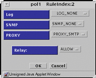
The only flag for the SMTP proxy is to allow or disallow relayed mail.
-
PROXY_Telnet - Presents the dialog box shown in FIGURE 5-39.
Figure 5-39 PROXY_Telnet Dialog Box for ALLOW action
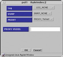
For the PROXY USER field, type the proxy user or the group of proxy users that you want for this rule from the choice list. Specify only one proxy user or one group of proxy users in this field. Define these proxy users in the proxy user common object.
DENY Action
FIGURE 5-40 shows the Policy Rule Index dialog box for DENY action
Figure 5-40 Policy Rule Index Dialog Box for DENY Action
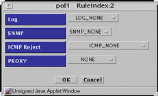
TABLE 5-39 describes the controls in Policy Rule Index dialog box for DENY action.
Table 5-39 Controls for DENY Action
-
PROXY_HTTP - Presents the same dialog box shown in Figure 5-40 save that PROXY_HTTP appears in the PROXY field. There are no flags to set.
-
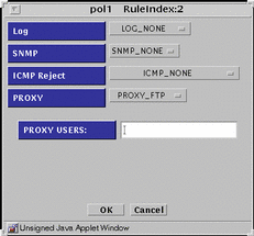
PROXY_FTP - Presents the dialog box shown in FIGURE 5-41.
Figure 5-41 PROXY_FTP Dialog Box for DENY action
-
PROXY_SMTP - Presents same dialog box shown in Figure 5-40 save that PROXY_SMTP appears in the PROXY field. There are no flags to set.
-
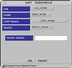
PROXY_Telnet - Presents the dialog box shown in FIGURE 5-42.
Figure 5-42 PROXY_Telnet Dialog Box for DENY action
ENCRYPT Action
FIGURE 5-43 shows the Policy Rule Index dialog box for ENCRYPT action.
Figure 5-43 Policy Rule Index Dialog Box for ENCRYPT Action
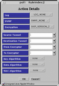
TABLE 5-40 describes the controls in Policy Rule Index dialog box for ENCRYPT action.
Table 5-40 Controls For ENCRYPT Action
SECURE Action
FIGURE 5-44 shows the Policy Rule Index dialog box for SECURE action
Figure 5-44 Policy Rule Index Dialog Box for SECURE Action
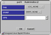
TABLE 5-41 describes the controls in Policy Rule Index dialog box for SECURE action.
Table 5-41 Controls for SECURE Action
Administrative Access Tab
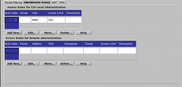
The Administrative Access rules tab shows access and encryption settings for local and remote administration. FIGURE 5-45 shows the Administrative Access tab. You set the values reflected on the two panels of this tab through the dialog box for each panel.
Figure 5-45 Administrative Access Tab
Access Rules for GUI Local Administration
Use the Access Rules for GUI Local Administration dialog box, shown in FIGURE 5-46, to add or modify administrative access rules for local Administration Stations.
Figure 5-46 Local Access Rules Dialog Box

TABLE 5-42 describes the controls for the Local Access Rules dialog box.
Table 5-42 Controls for the Local Access Rules Dialog Box
The Access Rules for Remote Administration
Use the Remote Access Rules dialog box, shown in FIGURE 5-47, to add or modify administrative access rules for remote administration stations. The certificates used here must be of the same strength and type as those defined in the screen object. The entries here determine what type of remote Administration Station the Screen will accept. The Screen only uses the administration certificate field of the Screen object here.
Figure 5-47 Remote Access Rules Dialog Box
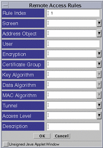
TABLE 5-43 describes the controls for the Remote Access Rules dialog box.
Table 5-43 Controls for the Remote Access Rules Dialog Box
NAT Tab
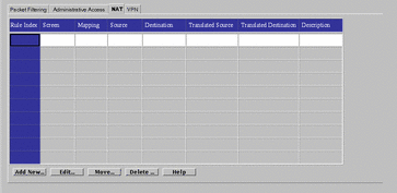
Use the Network Address Translation (NAT) tab, shown in FIGURE 5-48, to set up mapping rules to translate IP addresses according to specific rules. These rules interpret the source and destination of incoming IP packets, then translate either the apparent source or the intended destination, and send the packets on. You can map hosts, lists of addresses, ranges of addresses, or specific groups, depending on what you have configured in your SunScreen installation. See "Address" for information on defining addresses, ranges, or groups of addresses.
Figure 5-48 NAT Tab
In general, you map addresses to:
-
Ensure that internal addresses appear as registered addresses on the Internet, or
-
Send traffic for a specific destination to a different, predetermined destination.
Translating both source and destination addresses is not possible--that is, making packets appear to come from a different IP address and directing the packets to a different destination simultaneously is not possible.
When defining NAT rules, the first rule (lowest number) that matches a packet is the one that applies, and no other rules can apply; define specific rules first, then broader cases later.
FIGURE 5-49 shows the NAT Definition dialog box.
Figure 5-49 NAT Definition Dialog Box
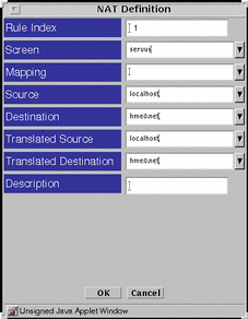
TABLE 5-44 describes the controls for the NAT Definition dialog box.
Table 5-44 Controls for the NAT Dialog Box
When defining rules, remember that translating both source and destination addresses is not possible. Either translate packets so they appear to come from a different source, or translate packets so they go to a specific destination, but not both.
All static NAT rules are unidirectional--that is, they work precisely as defined, and are not interpreted as also applying in the reverse direction. For rules to apply in both directions, specify two different rules. For example, if you map the source address internalname.com to the destination publicip.com, you will also have to map the source publicip.com to the destination internalname.com to translate traffic in both directions.
VPN Tab
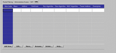
The VPN tab, shown in FIGURE 5-50, allows you to define VPN gateways. Defining VPN gateways using this mechanism simplifies the creation of VPNs that include more than two gateways and are managed in a centralized management group.
Note -
Each gateway in this type of configuration must be able to connect to the other ones directly--without going through another gateway.
Figure 5-50 VPN Tab
Setting up a VPN requires:
-
Choosing a name for the VPN.
-
Defining the VPN gateway.
-
Adding a rule for the VPN.
Defining VPN Gateways
Use the VPN Definition box, shown in FIGURE 5-51, to define and edit VPN gateways.
Figure 5-51 VPN Definition Dialog Box
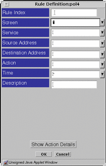
TABLE 5-45 describes the controls in the VPN Definition dialog box for defining VPN gateways.
Table 5-45 Controls in the VPN Definition Dialog Box|
Control |
Descriptions |
|---|---|
|
Rule Index |
(Optional) Assigns a number to a rule. By default, this field displays a number one greater than the last rule (indicating this rule will be placed the end of the list). Typing a lower number inserts the new rule into the specified position in the list and renumbers the rules currently in the configuration. Rules take effect in order. |
|
Name |
Specifies the Name of the VPN to which this gateway belongs. Type the same name in the Name field for each gateway that is in the VPN. |
|
Address |
Specifies the machine to be included in the VPN. |
|
Certificate |
Specifies the name of the certificate for this VPN gateway. |
|
Key Algorithm |
Specifies the secret (key) algorithm the VPN uses. All gateways in the same VPN must use the same (key) algorithm. |
|
Data Algorithm |
Specifies the data algorithm the VPN uses. All gateways in the same VPN must use the same data algorithm. |
|
MAC Algorithm |
Specifies the MAC algorithm the VPN uses. All gateways in the same VPN must use the same MAC algorithm. |
|
Tunnel Address |
Specifies the destination address on the outer (unencrypted) IP packet to which tunnel packets are sent. |
|
Description |
(Optional) Provides a short description of the VPN gateway. |
|
Add New |
Allows adding a new VPN rule. |
|
Edit |
Allows you to edit the VPN rule that you highlighted in the NAT tab. |
|
Move |
Allows assigning a new rule index number for the rule highlighted in the NAT tab. |
|
Delete |
Deletes the access rule highlighted in the VPN tab. |
|
Help |
Displays the online help. |
Adding a VPN Rule
After defining the gateways in a VPN, add a packet-filtering rule for this VPN. Add the packet-filtering rule using the Packet Filter tab.
When adding a packet-filtering rule for a VPN, leave the Screen field empty.
-
Specify SECURE for the packet-filtering action.
-
Type the name of the VPN in the VPN field.
Note -Use any address in the VPN rules. Only addresses that interact with a VPN Gateway and the address specified in the rule will apply. The simplest rule uses * for the source and destination address. This rule allows encrypted use of the specified service for all addresses in the VPN.
- © 2010, Oracle Corporation and/or its affiliates
