| C H A P T E R 4 |
|
System Interconnect |
The sections in this chapter contain a full description of the Sun Fireplane interconnect.
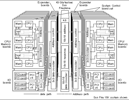
FIGURE 4-1 shows an overview of the Sun Fire 15K/12K systems interconnect. The small numbers in the block diagram are peak data bandwidths at each level of the interconnect.

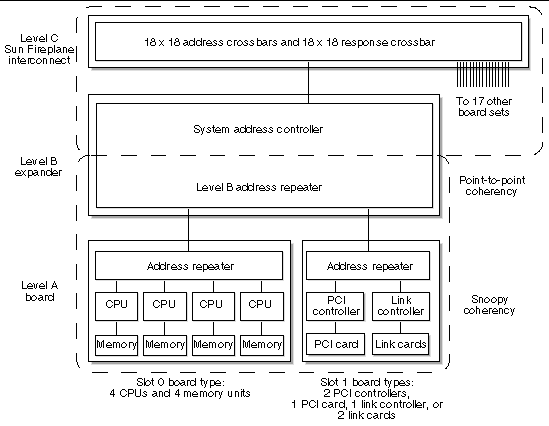
The Sun Fire 15K/12K systems interconnect is implemented in several physical layers (FIGURE 4-2). The realities of physical packaging make it impractical to connect all the functional units (CPU/Memory units, I/O controllers) of a large server directly together. The system interconnect of a server is implemented as a hierarchy of levels: chips connect to boards, which connect to the Sun Fireplane interconnect. The latency is lower and the bandwidth is higher between components on the same board, because there are more connections between them than there are to off-board components.

The system has two separate interconnects, one for address interconnect and another for data transfer interconnects (TABLE 4-1).
A The address repeater on each board or I/O assembly collects address requests from the devices on that board and forwards them to the system address controller on the expander board.
B Each board set expander has a snoopy address bus, with a coherency bandwidth of 150 million snoops per second.
C The 18x18 Sun Fireplane interconnect address and response crossbars have a peak bandwidth of 1.3 billion requests and 1.3 billion responses per second.
0 Two CPU/Memory pairs are connected by three 3x3 switches to the board-level crossbar.
1 Each CPU/Memory board has a 3x3 crossbar between its system port and two pairs of CPUs. Each PCI board has a 3x3 crossbar between its system port and two PCI bus controllers.
2 Each expander board provides a 3x3 crossbar between its Sun Fireplane interconnect port and two system boards.
3 The 18x18 Sun Fireplane interconnect data crossbar has a total bandwidth of 43 Gbytes per second, with a 4.8-Gbyte per second port to each of the 18 board sets.
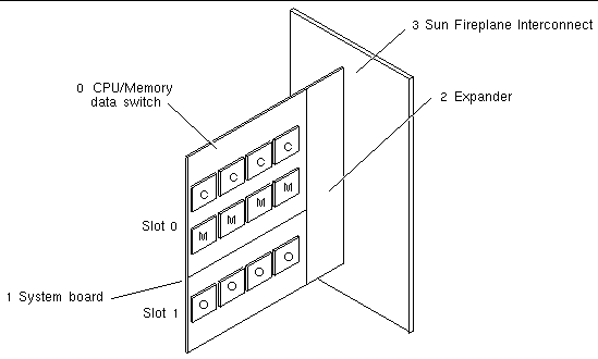
The Sun Fire 15K/12K systems have an additional level of interconnect that connects two boards to the Sun Fireplane interconnect port. This interconnect is the expander.
board set: |
||
CPU/Memory: |
In the Sun Fire 15K/12K systems, latency is lowest to memory on the same board because fewer levels of logic have to be crossed.
The Sun Fire 15K/12K systems address interconnect has three levels of chips (FIGURE 4-3).

An address passes through five chips to get from a CPU to a memory controller on another board. In the Sun Fire 15K/12K systems, addresses going to memory on the same board set do not consume any Sun Fireplane interconnect address bandwidth.
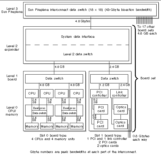
The Sun Fire 15K/12K systems data interconnect has four levels of chips. (See FIGURE 4-4.)
Level 0--CPU/Memory level. The five-port dual CPU data switch connects two CPU/Memory pairs to the board data switch. A CPU and a memory unit each have a 2.4-Gbyte per second connection and share a 4.8-Gbyte per second connection to the board data switch with the second CPU and memory unit.
Level 1--Board level. The three-port board data switch connects the on-board CPUs or I/O interfaces to the expander data switch. Slot 0 boards have a 4.8-Gbyte per second switch, and slot 1 boards have a 1.2-Gbyte per second and a 2.4-Gbyte per second switch.
Level 2--Expander level. The three-port system data interface connects two boards to the system data crossbar. The slot 0 board (four CPUs and memory) has a 4.8-Gbyte per second connection, and the slot 1 board (hsPCI-X/hsPCI+ or MaxCPU) has a 2.4-Gbyte per second connection.
Level 3--Sun Fireplane interconnect level. The 18x18 Sun Fireplane interconnect crossbar is 32 bytes wide with a system bisection bandwidth of 43 Gbytes per second.
Data passes through seven chips to get from memory on one board to a CPU on another board. In the Sun Fire 15K/12K systems accesses going to memory on the same board set do not consume any Sun Fireplane interconnect data bandwidth.
The numbers in FIGURE 4-4 refer to the peak bandwidth at each level. All data paths are bidirectional. The bandwidth on each path is shared between traffic going into a functional unit and traffic going out of a functional unit.

This section briefly quantifies the interconnect latency and bandwidth of the Sun Fire 15K/12K systems. Bandwidth is the rate at which a stream of data is delivered. TABLE 4-2 shows the peak memory bandwidths, as limited by the interconnect implementation. Memory is assumed to be interleaved 16 ways across the four memory units on one board.
Same-board peak bandwidth: These cases occur when all memory accesses go to memory on the same board as the requester.
The maximum same-board bandwidth is 9.6 Gbytes per second per board. This occurs when one of the following takes place:
The minimum same-board peak bandwidth is 4.8 Gbytes per second per board. This occurs when all four CPUs access memory on the other half of the board. When memory is interleaved 16 ways (the normal case), the peak bandwidth is 6.7 Gbytes per second per board.
Off-board bandwidth: The off-board data path is 32 bytes wide x 150 MHz, which equals 4.8 Gbytes per second. Because this bandwidth serves both outgoing requests from the board CPUs and incoming requests for memory from other CPUs, the per-board bisection bandwidth is halved, to 2.4 Gbytes per second.
Latency is the time for a single data item to be delivered from memory to a CPU. Several kinds of latency can be calculated or measured. Two latencies are described as follows:
These latency numbers represent the best-case example for a single CPU accessing memory.
Pin-to-pin latency is calculated by counting clocks in the interconnect logic design between the address request from a CPU and the completion of the data transfer back into the CPU. (See TABLE 4-3 and TABLE 4-4.)
|
CDC[1] Hit |
Increase Latency Conditions[2] |
||
|---|---|---|---|
|
CDC[3] Hit |
Increase Latency Conditions[4] |
||
|---|---|---|---|
|
On requester board
|
|||
Copyright © 2006, Sun Microsystems, Inc. All Rights Reserved.