| C H A P T E R 5 |
|
System Components |
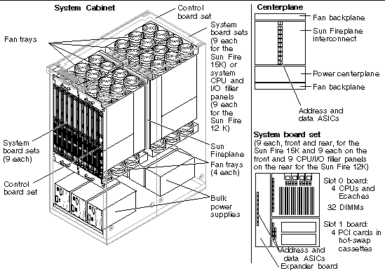
The sections in this chapter describes the major components used in the Sun Fire 15K/12K systems (FIGURE 5-1).

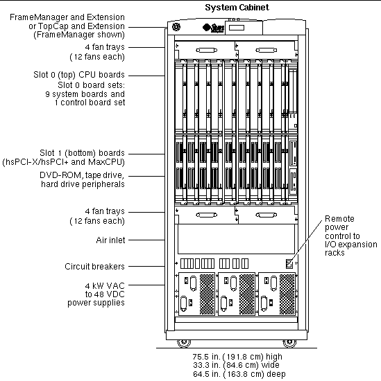
The Sun Fire 15K/12K systems can consist of two or more air-cooled cabinets: a system cabinet and one or more customer-selected I/O expansion racks (FIGURE 5-2). The system cabinet includes the CPU/Memory and system control peripherals.

The system cabinet is configured with a full complement of eight fan trays, six bulk power supplies, and two System Control board sets, which perform RAS services. (See Section 5.3.2, Controller Board Set.)
In the Sun Fire 15K system, up to 18 system board sets can be configured to determine the number of CPUs and the amount of memory per system. In the Sun Fire 12K system, up to 9 system board sets can be configured to determine the number of CPUs and the amount of memory per system. (See Section 5.3.1, System Board Set.)
A fully loaded Sun Fire 15K system cabinet weighs 2,467.8 lbs (1,121.7 kg). A fully loaded Sun Fire 12K system cabinet weighs 2141.0 lbs (987.0 kg).
The Sun Fire 15K systems run 200-240 VAC, single-phase power with a frequency of 47 to 63 Hz. The system cabinets require twelve 30-amp circuits, which are usually connected to two separate power sources. In North America and Japan, the site power receptacles are NEMA L6-30P; otherwise, they are IEC 309. The power cables that go between the system and the facility power receptacles are supplied with the system.
The system cabinets use six dual-input 4 kW dual AC-DC bulk power supplies. Two power cables go to each supply. These supplies convert the input power to 48 VDC. These systems can run with a failed bulk power supply, and the bulk power supplies can be replaced while the system is in operation.
Power is distributed to the individual boards through separate DC circuit breakers. Each board has its own on-board voltage converters, which transform 48 VDC to the levels required by the on-board logic components. Failure of a DC-to-DC converter affects only that particular system board.
The only operating environment limitations of the Sun Fire 15K/12K systems are:
The fully loaded systems draw 24 kW of power and have an air-conditioning load of approximately 77,860 BTU/hour for the Sun Fire 15K system and approximately 36,570 BTU/hrs for the Sun Fire 12K system. Smaller configurations draw less power.
For single Sun Fire 15K system or single Sun Fire 12K system heat dissipation, each system needs perforated tiles under the unit. Each tile needs to be capable of delivering 600 cubic feet per minute of cooling air. Rows of fully loaded system cabinets can be located adjacent to each other. Refer to the Sun Fire 15K/12K Systems Site Planning Guide for further details.
The air goes in through air inlets in the bottom, front, and back of the system cabinet and out through the top. Four fan trays are located above the system boards, and four are located below. The fans have three speeds that normally run at high speed. If any of the components get too hot, the fans are switched to super-high speed. The system is capable of running with a failed fan, and the fan trays can be hot-swapped while the system is running.
FIGURE 5-3 shows how the boards and fan trays on one side of a Sun Fire 15K/12K systems connect into the fan backplane, the power centerplane, and the Sun Fireplane interconnect.
A slot 0 board and a slot 1 board connect into a system carrier plate with an expander board, which in turn connects into the Sun Fireplane interconnect. This unit is called a board set. (See Section 5.3, System Boards.)
Nine system board sets connect into each side of the Sun Fireplane interconnect with a system carrier plate and the expander, slot 0 through 8 (front side) and slot 9 through 17 (rear side) of the Sun Fire 15K system. Nine system board sets connect into the front side of the Sun Fireplane interconnect with a system carrier plate and an expander, slot 0 through 8 and nine CPU and I/O filler panels slide into slot 9 through 17 (rear side) of the Sun Fire 12K system. Two system controller board sets (System Control board and System Control peripheral board) connect into each side of the Sun Fireplane interconnect with the system control carrier plate and the centerplane support board, slot SC0 (front side) and slot SC1 (rear side). Power is distributed to all board sets through the power centerplane which is located beneath the Sun Fireplane interconnect.
The Sun Fireplane interconnect has two dedicated slots (both on the right side, front and rear) for the system controller board sets. These board sets contain power, clock, and JTAG support for the Sun Fireplane interconnect ASICs and hold the System Control boards and their associated peripherals (DVD-ROM, tape drive, and hard drive).
Four fan backplanes are mounted above the Sun Fireplane interconnect, and four are mounted below the power centerplane, distributing power to the eight fan trays.
The Sun Fireplane interconnect is the heart of the Sun Fire 15K/12K systems and provides a peak data bandwidth of 43 Gbytes per second among the 18 board sets. The Sun Fireplane interconnect also delivers a console bus and an Ethernet connection to each board set.
The Sun Fireplane interconnect contains three 18x18 crossbars. The 18x18 address crossbar provides a path for address transactions between the address extender queue (AXQ) ASIC on each expander board. A pair of unidirectional paths goes to each expander board, one sending and one receiving. Each address transaction takes two system-interconnect cycles (13.3 ns) to be transmitted across the address crossbar.
The 18x18 response crossbar provides a reply path between the AXQ ASIC on each expander board. Each response message takes either one or two system-interconnect cycles (6.7 ns or 13.3 ns), depending on the type. The response path is half the width of the address path. A pair of unidirectional paths goes to each expander board, one sending and one receiving.
The 18x18 data crossbar moves cache-line (72-byte-wide) packets between the system data interface (SDI) ASICs on each expander board. Each connection is a bidirectional 36-byte-wide path. The bandwidth is 18 slots x 32-byte path x 150 MHz divided by two for bidirectional paths that are equal to 43.2 Gbytes per second. To maximize the use of these bidirectional paths, the data multiplexer (DMX) ASICs queues received data.
A board set is a combination of three system boards that connect into the Sun Fireplane interconnect. It is also called an expander. There are two types of board sets:
A system board set is a combination of three boards, an expander board, a slot 0 board, and a slot 1 board. The board set, as a unit, cannot be hot-swapped from the Sun Fireplane interconnect. Due to the weight of the components, the slot 0 and slot 1 boards are individually removed first, and then the expander and its carrier plate can be hot-swapped. The individual slot 0 and slot 1 boards can be hot-swapped from the expander.
Slot 0 boards have a 4.8 Gbyte per second off-board data port. They are the primary locations of CPUs and are the only location of memory in a Sun Fire 15K/12K systems. Only one Slot 0 board type is used in the Sun Fire 15K/12K systems.
Slot 1 boards have a 2.4 Gbyte per second off-board data port. There are two slot 1 board types: hsPCI-X/hsPCI+ and MaxCPU, which are unique to the Sun Fire 15K/12K systems server.
An expander board acts as a 2:1 MUX to expand a Sun Fireplane interconnect slot so that it accommodates the slot 0 and slot 1 type boards. The expander board provides a level-2 address bus that can do 150 million snoops per second. The AXQ on the expander board recognizes addresses targeted at other board sets and transmits them across the Sun Fireplane interconnect.
The expander provides a three-port data switch to route data between the slot 0 board, the slot 1 board, and the Sun Fireplane interconnect. This three-port data switch is 36-bytes wide to the Sun Fireplane interconnect and to the slot 0 board, and 18 bytes wide to the slot 1 board. A board set can transfer a maximum rate of 4.8 Gbytes per second to other board sets.
It is possible to use an expander with only one system board (either slot 0 or slot 1). A system board can be hot-swapped into the expander, tested, and configured into a running system without disturbing the other board. The expander can be hot-swapped and inserted after its two system boards are removed.
The CPU/Memory board is a slot 0 board. It contains up to four CPUs and eight external cache DIMMs. Each CPU controls 0, 4, or 8 DIMMs. The maximum possible DIMM size is 2 Gbytes, which is 64 Gbytes of memory per board. DIMMs must be the same size and must not have sizes intermixed on a board. All CPUs on the board must be the same speed.
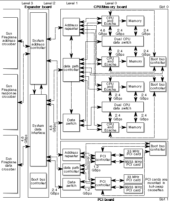
Two CPU/Memory pairs are connected to the rest of the system through the level-0 dual CPU data switch. Each CPU/Memory can transfer data at a maximum rate of 2.4 Gbytes per second. The pair of CPU/Memory units share a 4.8 Gbyte per second port to the data switch. The level-1 data switch connects the two pairs of CPUs to the off-board data port that goes to the expander board. (See FIGURE 5-4.)
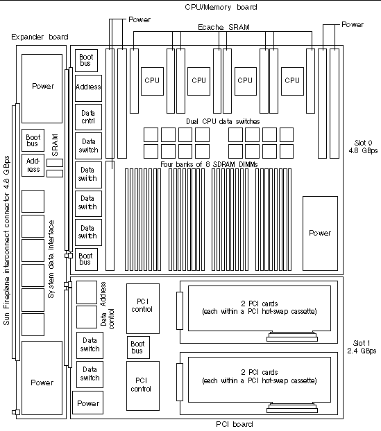
FIGURE 5-4 and FIGURE 5-5 show an example board set diagram and board set layout composed of an expander board, a CPU/Memory board, and a PCI board.
The PCI assembly is a slot 1 option board. Each hsPCI-X assembly has two PCI controllers and provides four PCI slots (one at 33 MHz and three at 33/66/90 MHz).The hsPCI+ assembly also has two PCI controllers and provides four PCI slots (one at 33 MHz and three at 33/66 MHz). Each hsPCI+ assembly provides four standard PCI slots, two at 33 MHz and two at 33/66 MHz. The assembly has two PCI controllers, each of which provides a 33 MHz PCI bus and a 33/66 MHz PCI bus.
A cassette is used to provide hot-swap capabilities for industry-standard PCI assemblies. The cassette is a passive card carrier that adapts the standard PCI pins to a connector.
A PCI card is placed into a PCI hot-swap cassette, and then the cassette is hot-swapped onto the PCI assembly. The software recognizes this assembly as a standard PCI assembly with the system controller turning power on and off to each PCI slot. (See FIGURE 5-4.)
The MaxCPU board is a slot 1 board. It has two CPUs but does not include any memory. This board enables CPUs to replace PCI cards in system configurations when more CPU power, instead of I/O connectivity, is necessary.


The controller board set provides critical services and resources required for operation and control of the Sun Fire 15K/12K systems (FIGURE 5-6).
This board set consists of three boards:
The System Control board is a two-board combination:
The system controller board set provides the following critical services and resources required for operation and control of the Sun Fire 15K/12K systems:
The SPARCengine cPCI card is mounted flat and on top of the SC in the same manner that the PCI cards are mounted onto the I/O boards.
Copyright © 2006, Sun Microsystems, Inc. All Rights Reserved.