| C H A P T E R 2 |
|
Environmental Requirements |
This chapter details the temperature and humidtiy requirement for Sun Fire E25K/E20K systems.
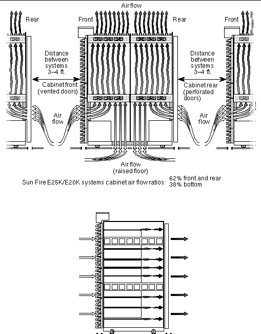
The design of the environmental control system (such as computer room air conditioning units) must ensure that intake air to the system meets the requirements specified in this section. Air enters the cabinet through the access panels and through an air intake that is located underneath the system cabinet. The heated air is exhausted out of the top of the system cabinet. Overheating can occur if warm air is directed underneath a cabinet or toward the access panels. TABLE 2-1 provides the environmental requirements for Sun Fire E25K/E20K systems and the customer-selected I/O expansion racks. If the system is significantly colder (40 °F [4 °C] or colder) than the environment in which you will install it, leave the system in its shipping crate at its final destination for 24 hours to prevent thermal shock and condensation.
The ambient temperature range of 70 degrees F to 74 degrees F (21 degrees C to 23 degrees C) is optimal for system reliability and operator comfort levels. Most computer equipment can operate within a wide temperature range, but a level near 72 degrees F (22 degrees C) is desirable because it is easier to maintain safe associated relative humidity levels at this temperature. Operating in this temperature range provides a safety buffer just in case the environmental support systems go down for a period of time. Though individual standards vary slightly, 70 degrees F to 74 degrees F (21 degrees C to 23 degrees C) should be used as an optimal temperature choice.
The ambient relative humidity levels between 45% and 50% are the most suitable for safe data processing operations. Under certain circumstances, most processing equipment can operate within a fairly wide environmental range (20% to 80%), but the optimal goal should be between 45% to 50% because this range:
Electrostatic discharge (ESD) is easily generated and less easily dissipated in areas where the relative humidity is below 35%, and becomes critical when levels drop below 30%. The 5% relative humidity range might seem unreasonably tight when compared to the guidelines used in typical office environments or other loosely controlled areas, but it is not so difficult to maintain in a data center because of the high efficiency vapor barrier and low rate of air changes normally present.
TABLE 2-2 and TABLE 2-3 provide air conditioning information for Sun Fire E25K/E20K systems components based upon the maximum system configuration. Use the worksheet in TABLE 2-3 (see Appendix A for an expanded form to use and retain for your records) to determine your system power and cooling requirements. This worksheet will assist you in calculating your total system power consumption in power (watts) and the total system air conditioning required in British thermal units (BTUs/hrs). The amount of air conditioning required depends upon your configuration.
The dynamics of the Sun Fire E25K/E20K systems power dissipation depends on the application and configuration. This manual accounts for these dynamics and is based on a rigorous code condition set that has been verified in a lab environment. During these tests, all measurements were taken with the latest-technology, high-speed current probe connected to the 48-volt side. The numbers were then changed to account for efficiency loss and power factor correction.
Once the system configuration (based on the number of system boards and I/O configuration) is determined, the environmental cooling requirements must be calculated. It is important that the site is able to accommodate the appropriate environmental requirements. The numbers in this manual account for these requirements.
To facilitate future upgrades, always provide environmental cooling, not merely limited to the purchased configuration of system and I/O assemblies, but for the anticipated growth, or maximum power dissipation and cooling needs.
For example, although all cabinets are normally configured with a full-capacity power system, the actual system power dissipation might be much less than the maximum available, and will vary depending upon the number and type of configured components. Therefore, in the design phase of facility development, provide enough power and cooling capacity for the maximum configuration anticipated. When upgrading, system power dissipation will increase, which might require new site planning for power and cooling.
FIGURE 2-1 demonstrates the directions of the air flow within the system cabinet.

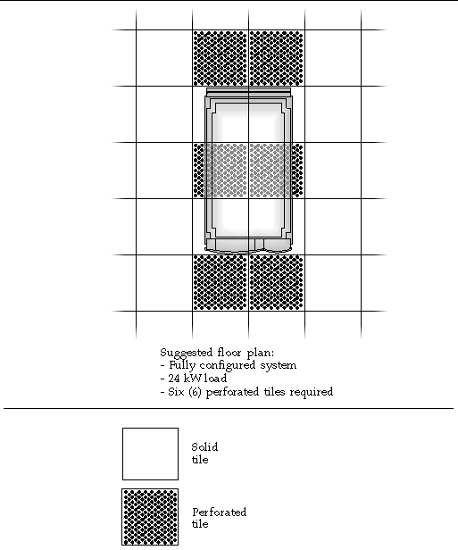
The fan tray redundancy in Sun Fire E25K/E20K systems provide enough air flow for adequate system performance on a flat floor. A raised floor is recommended for optimal system performance. Air enters the cabinet through the front and rear doors and through the air intake panels underneath the cabinet. Review the recommended floor plan layout sample for a fully configured system in FIGURE 2-2 for planning your solid and perforated tile floor configuration. This floor plan is based on floor tiles delivering 600 cubic feet per minute (cfm) cooling for each tile.
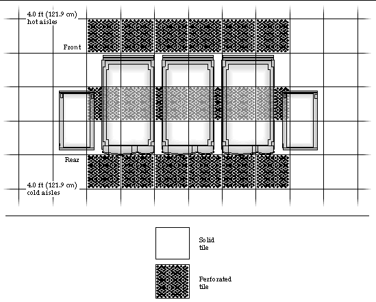
FIGURE 2-3 shows a floor plan layout for multiple Sun Fire E25K/E20K systems.
The maximum cable distance between the Sun Fire E25K system and the I/O rack is 157.5 in. (400 cm). If you are using a single-ended SCSI device for this connection, the connection cannot be made from the farthest rear corner of the system to the front top of the I/O rack, even if the rack is placed at the minimum distance requirement of 5.0 in (12.7 cm).

|
Note - Casters and leveling feet, located at the corners of each cabinet, are to be positioned only on solid floor tiles. |

|
Note - The system power cables are 157.5 in. (400.1 cm) long. Consider the maximum distance to a power receptacle when positioning the system. |
Copyright © 2007, Sun Microsystems, Inc. All Rights Reserved.